
Modeling allows for both additive and subtractive design practices. The purpose of our model needs to be taken into consideration before we start designing, as we have two distinctly different design methodologies we can utilize.
First, we can follow very strict and exact modeling, which is often the case when we are doing any product design or iterative work. This methodology is the most common, and occurs when we add dimensions to our models. This is known as Solid Modeling or Parametric Modeling. The second is more of an artist approach to modeling in which we model akin to shaping a piece of clay. This approach is most common while designing parts that have many free-flowing curved surfaces, such as the body of a car. This is known as Freeform Surface Modeling.
For our purposes, we will be utilizing the first approach, Solid Modeling, as this more closely relates to our architectural design applications.
We touched on a few design practices briefly in Chapter 1, A Primer on 3D Printing, in the MakerBot Replicator 2X limitations section, which we will now expand upon by using examples for several different design scenarios. What's most important is to consider that the printer functions by taking a 3D model, slicing it into n number of 2D layers, and applying material in areas specified by the cross-section. Keeping this in mind, we can see how some of the scenarios outlined in this section will produce unpredictable results.
3D printing requires that our object be a solid or has a volume rather than a surface. Surfaces are used inside CAD packages to create more complex shapes and add more control to model faces. Surfaces have the property of 0 thickness, and when we are ready to print, they must be explicitly given a thickness. The model must be watertight; think "creating volumes". Open objects are considered to be non-manifold.
For our purposes, an object will become nonmanifold if one of its edges or vertices is shared between two or more faces, as depicted in the following image figure, and also if it is not closed as previously described:
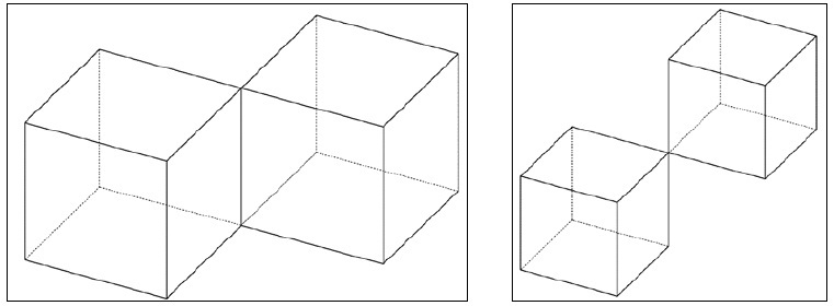
Nonmanifold edges and vertices
This is a very poor modeling practice and should be avoided at all cost, as it produces undesired and unpredictable results in both 3D printing and any simulation studies. The solution is to either connect the two bodies or create two entirely separate parts.
There are a number of websites and software packages available to help you fix questionable meshes. If you require more intensive mesh refinement features, you will most likely be looking at a paid software solution; however, for general fixing purposes, netfabb Basic is a free program worth checking out.
Tip
For more information on manifold conditions or common errors with nonmanifold objects, check out the link http://www.shapeways.com/tutorials/fixing-non-manifold-models.
This is a point that often gets overlooked. From experience, I recommend not going under 0.4 mm wall thickness in XY (0.4 mm is the thickness of the extruder nozzle) and 0.2 mm in Z (2 shells of the minimal layer height 0.1 mm). Going under this wall thickness most commonly produces small voids of material in the wall and other unpredictable errors. Walls below this thickness are also extremely flexible and break easily.
While the XY minimal wall thickness is fixed by the extruder nozzle diameter, the Z thickness is changeable. If our model contains a Z section that has a thickness of 0.2 mm, this can be achieved using the high (0.1 mm) layer resolution settings (more on this in Chapter 3, 3D Printing Software). Using a low (0.3 mm) layer resolution in this circumstance will result in unpredictable results. Therefore, the highest bound of your parts layer resolution settings will be dictated by the minimum layer resolution you expect to resolve.
Depending on the shape's geometry, some orientations will produce better, more accurate results. Consider trying to print a triangular wedge. If we orient the print upright (depth in XY), the last several layers leading to the point will be very fragile, whereas if we orient the print flat (depth in Z), we will produce smooth crisp corners.
Our model must fit inside the build volume. If it doesn't, there are several design changes that are left for us to debate as follows:
- Scale: Scaling will shrink every dimension of the model by the scale factor value. If you have any absolute values in your model (for example, a 1 mm screw hole), consider another option as this scales all the dimensions.
- Create multiple parts: Super glue is your best friend while working with the MakerBot, as it actually fuses ABS or PLA. Cut your model into two sections, print each section separately, and then super glue the pieces together. You can also add connection features (for example, slot and peg) to help align two parts together.
Tip
This technique of splitting and gluing is also often useful for parts where some components require greater accuracy or different orientations to improve quality. Rather than printing the entire model with high accuracy, you can make the high accuracy piece/section as its own model and simply glue it onto the base, which can save hours of print time.
- Redesign: Sometimes you have no other option than to go back to the drawing board.