
This chapter covers utilizing the multiple heads on the MakerBot Replicator (Dual Extruder) and Replicator 2X to print a single solid model composed of two different colors. In order to accomplish this, we must first briefly touch on the concept of assemblies and multibody parts before leading into a discussion about the MakerWare settings. Through this chapter, we will be redesigning our roof truss model used in Chapter 2, 3D Modeling Software, and Chapter 3, 3D Printing Software, which we will print using multiple colors. If you don't have a multihead printer, we also cover how to achieve the same multicolored part via Z Pause, and assemblies.
Look at any of the products around you, and chances are you'll notice that the vast majority of them are composed of one or more parts. As an example, this book (print- based not e-book) has text on pages which are bound together, which are also bound to a cover. If we assemble all these individual components (the pages, the binding, and the cover), we have a new model that is an assembly of components.
These components interact with one another in an explicit way, which is something we must specify. Referring back to our book example, the cover must go on the outside of the pages and the binding must attach the pages to both one another and the cover. These are properties of the assembly itself and are known as mates. Simple mates specify where in space each model is placed in relation to one another. There are more advanced mates which specify interactions during animation or simulation, but these are outside the scope of our use.
Multibody parts in the majority of scenarios are a bad design practice and should be avoided. A multibody part is a single model that has two bodies which do not connect. An example can be seen in the following figure:

A multibody model
Even though the model has two bodies, it is still considered one part. Certain modeling software allow us to extract each individual body into its own part. This is the software trying to help us adhere to proper design principles.
Experienced designers might use multibody parts to create more complex part geometries, but upon completion the bodies are always exported to individual files.
In Chapter 1, A Primer on 3D Printing, we talked about the two main types of materials and the recommended PLA as our material of choice, because it contracts much less than ABS during cooling. PLA comes in a wide variety of colors, thereby, letting us load separate colors into each of our extruders and print a single solid part in multiple colors. In addition to color, MakerBot also has translucent and glow-in-the-dark PLA. Note that to achieve the desired translucent effects, certain print settings are required (zero infill and a maximum of two shells), which needs to be taken into consideration while designing and printing.
MakerBot is always exploring/incorporating/creating new material options for use with the MakerWare software. The most recent advancement is MakerBot Flexible Filament, which for MakerWare v2.3.1, is only an available material option for The MakerBot Replicator 2.
Let's apply what we have just learned about assemblies and multibody parts to redesign our roof truss model from Chapter 2, 3D Modeling Software, and Chapter 3, 3D Printing Software, into an assembly.
The level of granularity that we choose will depend on what features we intend to highlight. In this example, we are choosing to highlight the gussets; therefore, we should make these components in their own models. For our wooden components, we could model these all individually and combine them with our gussets, which would be a more accurate representation of the real-world system. However, to reduce time and complexity, in our example we can print the entire wooden structure as one model. Here, we can see a tradeoff between accuracy, detail, time, and complexity, which is decided by which component(s) we are trying to emphasize. If instead of the gussets, we were instead emphasizing the chord or the Web, we might want to model those components individually. More granularity equals more complexity, which in turn equals more time.
Now that we have decided how we are going to model this assembly, let's begin to execute this plan.
- Extrude the wooden components to 2 mm using the same sketch from Chapter 2, 3D Modeling Software. The following image shows both the sketch and extruded product. We'll save the file as
ch4_woodenwith the extension defaulted by our CAD package. We are using SolidWorks for the examples in this book, so the file will bech4_wooden.sldprt.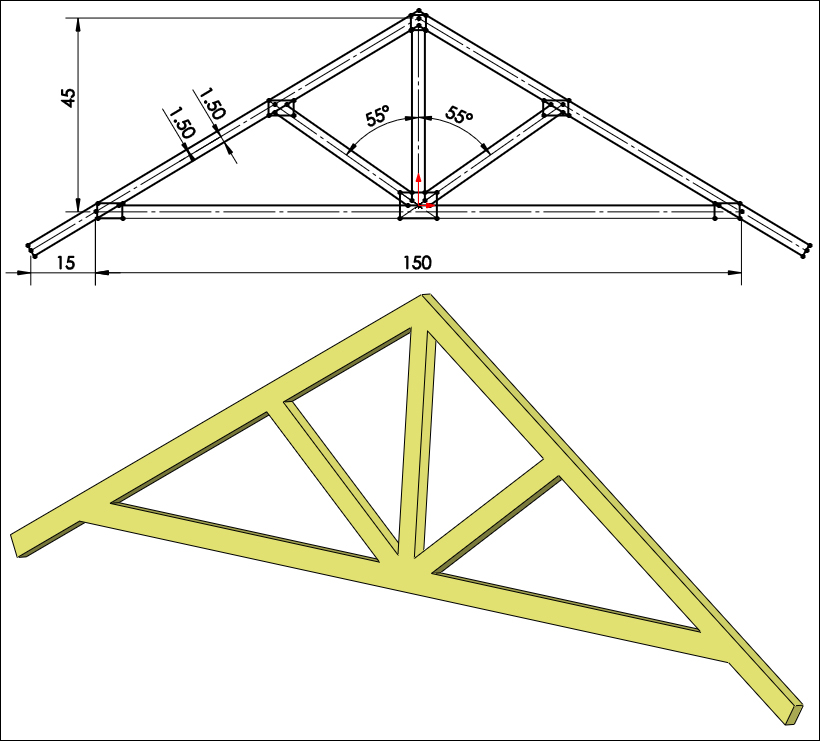
The sketch and wood extrude
- Next on our agenda is how we want to model the gussets. The first ideas that come to mind are to make a couple of different-sized gussets and perhaps add some top grooves to the gussets to give them a bit of texture. What's important to remember is that increasing complexity increases design and print time. For this example, let's design three different gussets: a large rectangle for connecting the bottom cords and the Web, a square for the very top, and a small rectangle for all the other locations. We'll give the gussets all a depth of 0.5 mm, 0.1mm larger than in Chapter 2, 3D Modeling Software. The following image shows dimensions for the three different gussets, which we will label
ch4_gusset_large,ch4_gusset_square, andch4_gusset_regularrespectively: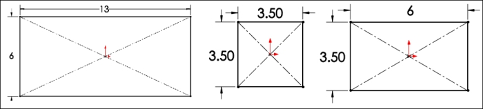
To the left is a large gusset, in the middle is a square gusset, and to the right is a regular gusset
- Add grooves to our gussets. But how deep should we make them? This will depend under what settings we want to print this part, and also what orientation. If we intend to use the same orientation from Chapter 2, 3D Modeling Software, and Chapter 3, 3D Printing Software, our Z axis will control our precision, which (if you remember) has a minimum height of 0.1 mm. If our grooves are not at least 0.1 mm deep, there is no guarantee that they will be printed at all even under the highest resolution. Conversely, if they are too deep (greater than 4 mm), there is no guarantee that the bottom will be printed. Any distance in between these maximums (0.1 mm to 0.4 mm) will be printed to the specified resolution.
Tip
There is no such way to achieve a precision greater than your specified resolution. Let's use a simple example of a sheet of paper that is 0.13 mm high. If we print this model with a precision of 0.1 mm we it measure afterwards, we will note the height to be 0.1 mm. The same holds true for the XY precision. As we might expect, this is caused by the process of 3D printing – layering material from a 2D cross-sectional outline.
- Cut the rectangular pattern for our grooves into our large gusset, as shown in the following screenshot. We have limited ourselves to printing this model using a High print resolution in order to follow the rule of thumb; that is, a minimum of two print layers. If we wanted to print the piece with a lower resolution, we would need to increase the thickness of our gussets.
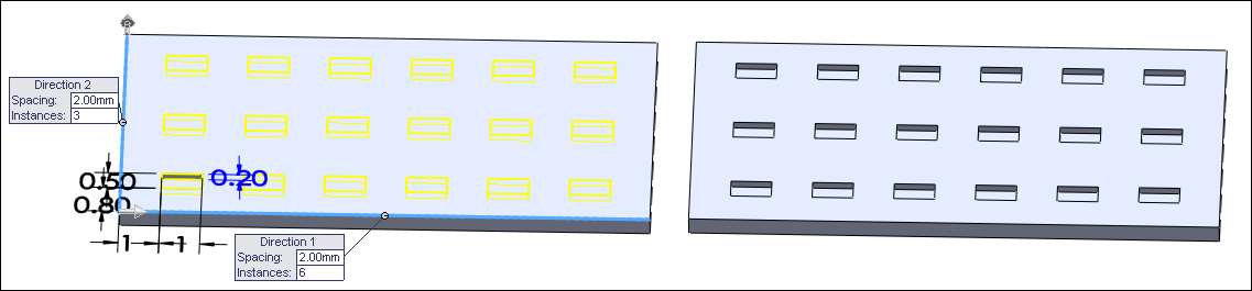
Gusset pattern cuts on a large gusset
- Create an assembly, insert all the parts, and using mates align the gussets. Our finished product should look equivalent to the roof truss we've used in the previous two chapters; the only difference is that we have an assembly of parts instead of one single part.
- Not all of the CAD programs have the ability to create assemblies. If your program lacks this ability, don't fret. You still can create multicolor parts either by designing multibodies and then exporting the files individually as we mentioned earlier, or by creating two models in separate files, then being very careful inside MakerWare when we orient the parts.
- The last step is to save the assembly as individual
.stlfiles, which will create multiple new.stlfiles—one for each component. Save the assembly asch4_roof_truss_assembly,and notice the 13 files (all beginning withch4_roof_truss_assembly_):ch4_wooden.stlch4_roof_truss_gussets_large-1.stlch4_roof_truss_gussets_large-2.stlch4_roof_truss_gussets_square-1.stlch4_roof_truss_gussets_square-2.stlch4_roof_truss_gussets_regular-1.stlch4_roof_truss_gussets_regular-2.stlch4_roof_truss_gussets_regular-3.stlch4_roof_truss_gussets_regular-4.stlch4_roof_truss_gussets_regular-5.stlch4_roof_truss_gussets_regular-6.stlch4_roof_truss_gussets_regular-7.stlch4_roof_truss_gussets_regular-8.stl
- We have eight regular gussets in our assembly (four on each side), and each has a different location; therefore, we must create four different
.stlfiles. All the files we created should have the parts positioned relative to one another. If not, our only option is to very carefully orient them inside MakerWare. Let's go ahead though; add these files to our MakerWare build platform, and begin exploring how to specify multiple colors.