
Let's go through a practical example of modeling and create a roof truss. We begin by sketching or finding an image of what we would like to model. We'll use the illustration below:

Common roof truss
Now we are faced with our first design decision: create the part with real dimensions and scale it for 3D printing or use prescaled dimensions to fit on the MakerBot platform. What you choose will depend on your application. The quickest way, if you already know you intend to print the model on the MakerBot, is to design for printing from the start. The disadvantage of this decision is that you are sacrificing some accuracy in the model, as you are designing to the MakerBots platform specifications; however, this only becomes important if you are doing quantitative testing or product development, whereas our application is more so a visual model. For this example, we will be designing to optimize for printing on our MakerBot from the beginning.
Let's consider a size for this model. For the purposes of simplicity, we'll have our entire model fit easily in the build platform. Thus, let's set a size of approximately half the build platform width for the bottom joist. Alternatively, we could have also chosen to model the truss as an assembly (grouping of several components) and put together all the parts after printing. Both options are valid.
Our last step before getting into the detailed design is to look for any problem areas that might arise. Looking at our original image seen previously, we notice the gussets. We must ensure that the XY-thickness of these gussets is above our absolute minimal wall thickness of 0.4 mm and the Z-thickness is above 0.1 mm (though we should aim for minimum of 2 walls thick). This appears to be the only area of concern, so now we can begin designing.
The CAD package we have chosen is SolidWorks; however, the approach when solid modeling with any of the aforementioned CAD packages (with the exception of TinkerCAD) will be very similar. We begin by creating a detailed 2D sketch of the model in our chosen CAD package as seen in the following figure:
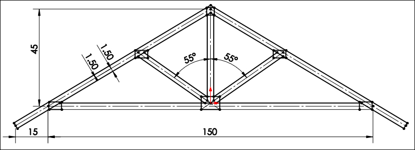
A common roof truss detailed sketch
From this point, we choose what sections of the sketch to extrude and to what distance. Let's give the gussets a 0.4 mm thickness and the beams 1 mm thickness as shown in the following figure:

A 3D model for roof truss
There we have it, one roof truss. We began by extruding the back gussets 0.4 mm, then extruded the beams 1 mm, and ended by extruding the front gussets 0.4 mm. From here, all that's left to do is to save our work. We have two possible choices of file format that work well with 3D printing software options, the most common being .stl (.obj is the second). We'll choose to save this file in the .stl format with the name ch2_roof_truss.stl.