
CHAPTER 12
GSM-MAP/ANSI 41 Integration
We have just discussed some of the radio system planning parameters of IMT2000DS—how to deliver adaptive radio bandwidth and how to deliver consistent-quality bandwidth, with sufficient resilience to support persistent rich media sessions between duplex users. We described how radio bandwidth quality is one necessary and important component in the delivery of end-to-end performance guarantees. These guarantees form part of a user's service level agreement, which includes admission rights and policy rights stored in the SIM/USIM.
Approaching a Unified Standard
In a GSM-MAP network, it is the SIM/USIM that dictates or at least describes the quality of service requirements of the user or the user's application. This in turn determines the allocation of radio and network resources. Radio resources are provided either over an IMT2000DS air interface (with backward compatibility to GSM, GPRS and E-GPRS air interfaces) or a CDMA2000 air interface (with backward compatibility to IS95A, B, C).
In addition to having two similar but different air interfaces, we have, worldwide, two similar but different mobility network standards:
ANSI 41 network. Any U.S. TDMA or CDMA2000 air interface, or any AMPS air interface, either in the United States or Asia, will have behind it an ANSI 41 network.
GSM-MAP network. Any GSM or IMT2000DS air interface, either in the United States, Europe, or Asia, will have behind it a GSM-MAP network.
The differences between the two networks are by no means unbridgeable, particularly as both use SS7 signaling to manage network functionality. One practical and important difference historically is that GSM-MAP networks have used the smart card SIM as the basis for controlling radio access to the network, that is, user specific authorization. The user buys a SIM card and can put it into any GSM phone. The SIM card, not the phone, is the device that determines the user's access and priority rights.
In IS41/ANSI 41 networks to date, SIM cards have not been used. Instead, the device is validated for use on the network by virtue of its mobile identity number (MIN) and equipment identity number (EIN). This is now changing, as 3GPP2 (the body working with 3GPP1 on IMT2000DS/CDMA2000 integration) now support the use of the SIM (which in CDMA2000 is actually called an R-UIM—removable user identity module) as an access validation platform.
3GPP1 and 3GPP2 are working together to use the SIM/R-UIM as a basis for bringing together GSM-MAP and ANSI 41. Parallel work is under way to implement GAIT handsets (GSM/ANSI 41 handset interoperability) and the side-by-side compatibility of an ANSI 41 network with the GERAN (GSM/GPRS/EDGE radio access network) and UTRAN (UMTS radio access network), as shown in Figure 12.1. The U-SIM/R-UIM is the mechanism for defining a user's policy/conditional-access rights and is becoming an integral part of the IPQoS proposition.

Figure 12.1 GSM-MAP/ANSI 41 integration.
The more radically inclined vendors see IP protocols as an additional mechanism for unification, potentially replacing existing Signaling System 7 (SS7) signaling, which is used to establish, maintain, and clear down telephone calls between users. SS7 provides the signaling control plane for wireless and wireline circuit-switched network topologies. It is a mature and stable standard. In a wireless network, additional functionality is needed to manage the allocation of radio channels (actually a channel pair for the uplink and downlink) and to support mobility management. This is known in GSM as GSM-MAP (Mobile Application Part).
SS7 is often described as an out of band signaling system—the signaling is kept functionally and physically separate from the user's voice or data exchange. In a packet-switched network, the routing of calls or sessions relies on a router reading the address on each packet or group of packets transmitted—an in-band signaling system using established Internet protocols (IP). There are standards groups presently working on bringing together IP and SS7 (IP SS7), and significant progress has been made on using both signaling systems to implement always on connectivity in wireline networks (for example, using ADSL).
The additional functionality needed to support wireless connectivity, however, creates a number of implementation problems, which are presently proving difficult to resolve. For example, in a GPRS network, a Packet Common Control Channel (PCCCH) and Packet Broadcast Control Channel (PBCCH) are needed to support always on connectivity. The PCCCH and PBCCH replace the existing Common Control Channel (CCCH) and Broadcast Control Channel (BCCH). There is presently no easy method for ensuring PCCCH- and PBCCH-compliant handsets are backward compatible with CCCH- and BCCH-compliant handsets. This sort of issue can be overcome, but it takes time.
In addition, some network operators question why they should abandon a tried and trusted signaling system that gives good visibility to system hardware performance (including warning of hardware failures) and is (accidentally) well suited to persistent session management. This is an important point. The first two parts in this book argued the case that session persistency would increase over time and become increasingly similar to voice traffic, although ideally with a longer holding time. As session persistency increases, out-of-band signaling becomes increasingly effective, which means session setup, session management, and session clear-down is directly analogous to call setup, call maintenance, and call clear-down.
IP could potentially replace SS7 but would need to emulate the session management and session reporting capabilities of SS7. We revisit this issue when we study traffic shaping and traffic management protocols, the subject of Chapters 16 and 17 in Part IV of this book.
Mobile Network Architectures
The traditional network architecture used in GSM-MAP and ANSI 41 is very hierarchical—a centralized mobile switch controller sits in the center of the network (see Figure 12.2). There may be a number of switches to cover a country. Each switch controls a number of base station controllers, which in turn support the local population of mobile users.
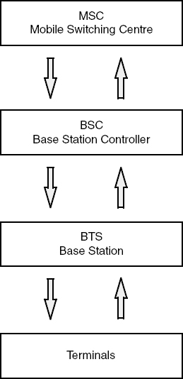
Figure 12.2 Traditional hierarchical network architecture.
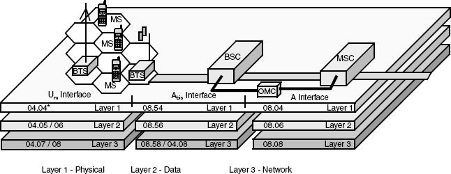
Figure 12.3 (see also the following key to the diagram) shows a GSM-MAP network. It is a conventional wireline network based on ISDN, but with a mobility management overlay (Mobile Application Part). This provides the additional functionality needed to move users from cell to cell (power control and handover); to set up, maintain, and clear down mobile calls; and to bill for services provided to mobile users.
Going from left to right, the base stations talk to the BSC over the A-bis interface. This interface takes the 9.6 kbps, 14.4 kbps, or 13 kbps voice traffic from the mobiles (with some embedded signaling) and moves the traffic to and from the BSC over typically multiplexed (120) 16 kbps traffic channels within a 2 Mbps pipe. In this example, voice traffic is then transcoded from the 13 kbps (or 12.2 kbps EFR) codec stream to a 64 kbps low PCM (pulse coded modulated) channel stream by the transcoder (TCE). An operation and maintenance center looks after hardware and channel monitoring.
At the middle of the diagram at the top we have the mobility management platform consisting of the Authentication Register, the Visitor Location Register, the Home Location Register, and the Equipment Identity Register. When a user is on his or her home network in his or her home country, he or she is logged into the Home Location Register. If the user travels to another country, the phone scans the 32 control channels standardized in GSM and camps onto a serving network (this will either be the strongest signal or a directed logon determined by inter network roaming agreements). The visited network will log the user into the Visitor Location Register.
The Visitor Location Register needs to let the user's home network know that the user has moved. If someone now phones the user's home number, the user's call will be forwarded—at some expense—to the user via the visited network. The authentication register looks after SIM/U-SIM based user authentication and the equipment identity register matches the user to the equipment being used. (Stolen equipment can be barred from the network.) These mobility management functions involve, as you would expect, substantial signaling, and this is carried over the SS7 signaling layer on 64 kbps multiplexed land lines.

Figure 12.3 GSM network (GSM-MAP).
KEY TO FIGURE 12.3
| AUC | Authentication Center |
| BSC | Base Station Controller |
| BTS | Base Transceiver Station |
| DAI | Digital Audio Interface–104 kbps |
| EIR | Equipment Identity Register |
| GSM | Global System for Mobile Comms |
| HLR | Home Location Register |
| ISDN | Integrated Services Digital Network |
| MS | Mobile Station |
| OMC | Operation and Maintenance Center |
| PLMN | Public Land Mobile Network–or Private |
| PSTN | Public Switched Telephone Network |
| VLR | Visitor Location Register |
| TCE | Transcoding Equipment |
The mobility management overlay provides the information needed for billing, so it is arguably the most commercially important component in the network.
Traffic to and from mobile users is consolidated in the switch—hardware routed on the basis of the target phone number used in the call setup procedure. If the call is mobile to mobile, for example, the end-to-end link is determined by the sender's IMSI number and the receiver's IMSI. When a call setup request is received at the MSC, the MSC uses Layer 3 (network layer) signaling to allocate access network resources for the call via a BSC and BTS. Layer 3 talks to Layer 2 (the data link layer) to allocate logical channel resources via the BTS to the mobile. Layer 2 talks to Layer 1 to acquire physical channel resources (that is, time slots within an RF channel in GSM/TDMA). Figure 12.4 shows this layer modeling.
This all works fine when the traffic in both directions is more or less constant rate on a per-user basis. Average call length in a cellular network is about 2 minutes. Traffic loading can therefore be very accurately predicted. On the basis of these predictions, decisions can be taken on how much backhaul bandwidth to install (how many 2 Mbps lines to install).
Average call length is actually getting longer year by year as call rates reduce, and, anecdotally, younger people also seem to take more than their parents' share of time on the phone. So call length is increasing as more young people start using mobile phones. This nevertheless still represents quite predictable loading.
Historically, transmission bandwidth in the MSC and copper access network has been overprovisioned to ensure that grade of service is more or less equivalent to fixed access PSTN in terms of availability (so-called five 9s availability). You pick up the phone, and 99.999 percent of the time, you get a line, or put another way, there is a 1 in 10,000 chance of the network being engaged. In practice, the limitation in a mobile network tends to be the radio resource rather than network resources. One of the major rationales of moving to a packet network, however, is to reduce the cost of network transmission.
In a circuit-switched network, a logical channel and physical channel are established end to end for the duration of the call. The logical channel and physical channel exists in two directions simultaneously. Over the radio interface, the channel is a duplex spaced RF channel pair 45 MHz or 190 MHz apart or (in TDD) an uplink and downlink time slot. In a duplex voice conversation, we are only talking for approximately 35 percent of the time; that is, for more than 50 percent of the time we are either listening to the other person or pausing (to draw breath) between words. A pure packet-routed network avoids this wasted bandwidth. Packets are only sent when voice activity is detected.
In defense of circuit-switched networks, it is valid to point out that there is a fundamental difference between logical channel allocation and physical channel allocation. Over the radio air interface, a logical channel pair will have been allocated for the duration of a duplex voice call. However, if the handset and the base station are using discontinuous transmission (RF power is only generated when voice activity is detected), then there is no physical occupancy of the radio layer.
Similarly, because much of the core transmission network has been historically overprovisioned and, in many cases, fully amortized, increasing core network bandwidth utilization is neither necessary nor cost-effective. We do need to take into account, however, the increasingly bursty nature of the traffic being offered to the network; that is, we are justifying the transition to packet networks on the basis of their suitability for preserving the properties of bursty bandwidth—a quality rather than cost-saving justification.
It is as problematic as it is difficult to put a finite value on quality; how much is a 24-bit color depth 15 frame per second video stream worth compared to a 16-bit 12 frame per second video stream. Additionally, we need to factor in the extra costs incurred by deploying packet routing in the network. Figure 12.5 shows the first changes that have to be made—the addition of a GPRS or packet traffic support node.
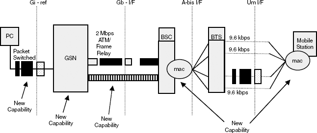
Figure 12.5 Packet-switched data service architecture (GSN-GPRS support node).
The GPRS support node talks to the BSC across a 2 Mbps (2.048 Mbps) ATM transport layer. (We case study ATM in Part IV of the book.) For the moment, all we need to know is that the ATM layer allows us to multiplex bursty traffic and maintain its time domain properties. What you put in at one end of the pipe comes out at the other end of the pipe unaltered—a bit like a filter with a constant group delay characteristic. The traffic experiences some delay because of the multiplexing—and some delay along the transmission path—but the delay is a constant and is equal for all offered traffic. At either end of the ATM pipe, we can, of course, buffer traffic and prioritize access in the ATM pipe. That is, traffic is all treated equally while it is inside the pipe but can be given differential transport priority before it gets into the pipe.
The example shown in Figure 12.5 highlights new MAC (Medium Access Control) functionality (Layer 2 functionality) in the mobile and BSC. This is to support high-speed circuit-switched data from a handset capable of using more than one time slot on the uplink and downlink; that is, variable bit rate can be delivered in increments of additional time slots (or in IS95, additional PN offsets). The A-bis and UM/IF interface, therefore, remains essentially unchanged.
Figure 12.6 shows the addition of a serving GSN that can manage simultaneous circuit-switch and packet-routed traffic talking to the gateway GSN using IPv6 (case studied later). The SGSN talks to the BSC over an ATM transport layer. The BSC talks to the BTS (also over ATM), and the BTS exchanges packets with the mobile using E-GPRS radio blocks to manage packet re-sends (covered earlier in Chapter 2, where we discussed system planning). It is interesting to note the continuing presence of an MSC and an interworking function to manage simultaneous packet-routed and circuit-switched traffic.

Figure 12.6 GPRS service platform–SGSN–serving GSN.
The forward compatibility selling point is that once an operator has put ATM in between the SGSN and BSC and BTS, it is then relatively easy to implement IMT2000DS with a MAC layer delivering dynamic rate matching on a 10-ms frame resolution, effectively wireless ATM. IPV6 can be used to provide some higher-layer prioritization of packet streams, establishing rights of access and priority/preemption entitlements to network and radio transmission bandwidth.
There is still (particularly in Europe and Asia) a strong circuit-switched feel to the network. ATM is a hardware-based implementation of virtual circuit switching. Remember also that the genesis of the 3GPP specification was to implement wireless ISDN over the radio physical layer.
GSM-MAP Evolution
The original standards documents described the three maximum data rates supportable. Originally the rates were 144 kbps, 384 kbps, and 2048 kbps—equivalent to IDSN 2B + D, ISDN HO, and the lowest entry-level ATM rate. Circuit-switched services would be supported up to 384 kbps, and higher data rates would be packet-switched; 144 kbps would be available in macrocells; 384 kbps would be available in microcells; and 2048 kbps would be available in picocells. The original chip spreading rate in the standard was 4.096 Mcps. This was chosen to support the ATM 2.048 kbps bearer—that is, 2048 kbps equals 1024 kilosymbols; 1024 kilosymbols times a chip cover of 4 equals 4.096 (1024 × 4).
The chip rate was then reduced. (This was done for political reasons, in the spirit of bringing the chip rate closer to the CDMA2000 chip rate.) However, as a consequence of this, adjacent channel performance improved. The cost was that the 2.048 kbps top user rate was reduced to 1920 kbps equivalent to ISDN H12—that is, 960 kilosymbols (960 × 4 = 3.84 Mcps), as shown in Table 12.1.
There is less focus now on ISDN partly because of the increased need to support very variable user data rates. So, for example, we still use the ISDN rates as a maximum user data throughput but effectively provide an ATM end-to-end wireless and wireline channel for each individual user's packet stream (or multiple per-user traffic streams). Given this shift in emphasis, it was decided to try and improve bandwidth utilization in the ATM copper access transport layer by maintaining the DTX (discontinuous transmission) used over the radio layer as traffic moved into the network core. This is implemented using a protocol known as ATM AAL2.
Table 12.1 Current Maximum Supportable Data Rates

Our good friend SS7 still stays very much in charge of traffic flow control, but there are proposals to implement broadband SS7 on the basis that the existing 64 kbps-based signaling pipes will become too small. This work is being presently undertaken by 3GPP alongside proposals to implement an IP-based signaling bearer known as SCTP/IP (Signaling Control Transport Plane using IP).
Some network operators and vendors remain unconvinced of the merits of using IP to replace existing (tried, trusted, and effective) signaling protocols, so progress on standardization might be rather slower than expected.
The IUB interface between the Node B and the RNC is 2048 kbps ATM (2.048 Mbps), and the IU interface is 155 Mbps ATM. DTX is implemented using AAL2 across the IUB and In interface (into the core network). Each individual RNC looks after its own family of Node Bs except, referring to Figure 12.7, where a mobile is supported by two Node Bs under separate RNCs. This has to be managed by the IUR interface used by the RNCs to talk to one another. The RNCs also have to manage load balancing, which we covered in the previous chapter.
A typical RNC is configured to support several hundred Node Bs. The RNC is responsible for mobility management, call processing (session setup, session maintenance, session clear-down), radio resource allocation, link maintenance, and handover control. Note the RNC needs to make admission control decisions looking out toward the Node B on the basis of radio layer noise measurements, and admission control decisions looking inward to the core network on the basis of network congestion.
We discuss the software needed for this (reasonably complex) process in Chapter 16.
GPRS Support Nodes
In the core network, we have the GPRS support nodes. These nodes have responsibilities, described in the following sections, which are carried forward into a 3GPP packet-routed 3G network.
The SGSN Location Register
The serving GPRS support node is responsible for delivering data packets to and from mobiles within its service area and looks after packet routing, mobility management, authentication, and charging. The SGSN location register stores the location information (current cell, current VLR) and user profiles (IMSI packet data network addresses) of all GPRS users registered with the SGSN.
The GGSN GPRS Gateway Support Node
The GGSN is the interface between the GPRS backbone and the external packet data networks. It converts GPRS packets from the SGSN into the appropriate packet data protocol (PDP) format (IP or X25). Incoming data packets have their PDP addresses converted to the GSM address of the destination user, and re-addressed packets are sent to the responsible SGSN. GSN to GSN interconnection is via an IP based GPRS backhaul. Within the backbone, PDN packets are encapsulated and transmitted using GPRS tunneling protocol.
A SGSN may need to route its packets over different GGSNs to reach different packet data networks.
Figure 12.7 shows the intra- and inter-PLMN (Public Land Mobile Network) interconnection. The intra-PLMN backbone connects GSNs of the same PLMN, that is, a private IP-based network specific to the GPRS network provider. Inter-PLMN backbones connect the GSNs of different operators (supported by an appropriate service level agreement).
The Gn and Gp interfaces allow the SGSNs to exchange user profiles when a user moves from one SGSN to another. The HLR stores the user profile, current SGSN address, and PDP for each GPRS user in the PLMN. The Gr interface is used to exchange information between the HLR and the SGSN. The Gs interface interconnects the SGSN and MSC/VLR database. The Gd interface interconnects the SMS gateway with the SGSN.
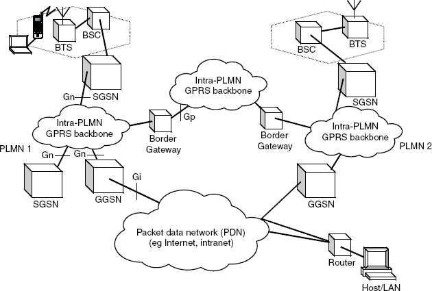
Figure 12.7 GPRS system architecture (routing example).
Table 12.2 GPRS Reliability Levels

GPRS bearer services include point-to-point (PTP) services, which can be connectionless or connection-oriented (for example, X25), or point-to multipoint (PTM) services, for example, supporting multicasting within a geographical area—traditionally referred to in PMR as open channel working or group calling.
GPRS QoS is based on simple service precedence, reliability, delay, and throughput. Service precedence is either high, normal, or low. Table 12.2 shows the three classes of reliability.
GPRS QoS also has four classes of delay, listed in Table 12.3.
Delay is defined as end-to-end transfer time between two communicating handsets or between a handset and the Gi interface to the external PDN. It includes delay for the request and assignment of radio resources and transit delay in the GPRS backbone. Transfer delays outside the GPRS network are not included; as presently specified, GPRS does not support end-to-end guaranteed QoS. Throughput is specified as maximum, peak bit rate, and mean bit rate.

Session Management, Mobility Management, and Routing
When you turn on your GPRS handset, it registers with the SGSN of the serving GPRS network. The network authorizes the handset and copies the user profile from the HLR to the SGSN. It assigns a packet temporary mobile subscriber identity (P-TMSI) to the user (GPRS attach). Detach can be handset or network initiated. After a successful attach, the handset must apply for one or more addresses used in the PDN, for example, an IP address. A PDP context is created for each session, for example:
- PDP type (IPv4/IPv6)
- PDP address
- Requested QoS
- Address of a GGSN serving as the access point to the PDN
The context is stored in the handset, the SGSN, and the GGSN.
Address allocation can either be static or dynamic. In static allocation, the network operator permanently assigns a PDP address to the user. In dynamic allocation, a PDP address is established when a PDP context is established (executed by the GGSN). This might be used, for example, to support prepay packet traffic.
To implement routing, the SGSN encapsulates the IP packets from the handset and examines the PDP context. The packets are routed through the intra-PLMN GPRS backbone to the appropriate GGSN. The GGSN decapsulates the packets and delivers them to the IP network.
Location Management
The network needs to keep track of where a GPRS user is physically to minimize uplink signaling and downlink delivery delay. The network has to rely on the GPRS handset telling it where it is—that is, which base station it is seeing.
The handset is either ready, in idle mode, or in standby, as follows:
- Ready means the handset has informed the SGSN of where it is.
- Idle means the network does not know the location of the handset.
- Standby means the network knows more or less where the handset (that is, within a certain location area subdivided into several routing areas, which will generally consist of several cell sites).
The status of the handset is determined by timeouts.
If an MS moves to a new RA, it produces a routing area update request to the SGSN. The SGSN assigns a new P-TMSI to the user. It does not need to inform the GGSN or HLR, since the routing context has not changed.
Micro and Macro Mobility Management
At a micro level, the SGSN tracks the current routing area or cell in which the handset is operating. At a macro level, the network needs to keep track of the current SGSN. This information is stored in the HLR, VLR, and Gateway GPRS Service Node (GGSN).
The more radical proposals of IP everywhere argue that the HLR, VLR, and GGSN could be replaced with DHCP servers, which could handle dynamic IP4 address allocation, subscriber profiles, and access policies using standard Microsoft Active Directory software. However, the HLR and VLR capability is very well proven within hundreds of GSM networks, so it is unlikely that this change will happen quickly if at all.
Radio Resource Allocation
It is important to differentiate physical and logical channels. A physical channel is denoted as a packet data channel (PDCH), taken from a common pool from the cell. Allocation can be driven by traffic load, priority, and multislot class (see Table 12.4).
Logical channels are divided into traffic and signaling (control) channels. One handset can use several PDTCH (data traffic) channels. A packet broadcast channel PBCH supports point-to-multipoint services and carries information on available circuit-switched bearers.
A handset-originated packet transfer can be done in one or two steps. The two-step process involves a resource request and then a channel assignment (logical channel request followed by physical channel assignment) or both steps can be done at once. On the downlink (base to handset), the handset is paged, the mobile requests a physical channel, and the packet is sent.
A physical data channel has a multiframe structure of 52 frames, which is 240 ms long. Note that a 26-frame multiframe (120 ms) is identical to an IMT2000DS multiframe (12 × 10 ms frames).
As the offered traffic is moved into the network, it is controlled by the data link and transport link layer protocols. GPRS tunneling protocol (GTP) is used to transfer data packets over the transmission plane managed by the GTP tunnel control and management protocol (using the signaling plane) to create, modify, or delete tunnels. UDP is used for access to IP-based packet data networks, which do not expect reliability in the network layer or below. IP is employed in the network layer to route packets through the backbone. All of the packets are carried by the ATM transport layer.
Table 12.4 Radio Resource Allocation Logical Channels

Operation and Maintenance Center
In Figure 12.3 we showed the OMC as a network component with responsibility for the physical transport links between the RNC and Node Bs, and legacy and 3G service platforms. The RNC monitors the status of the transport links in the network—for example, hardware or software failures. The network could be GPRS, EDGE, or UMTS (UTRAN) or any corporate virtual private network implemented by the operator. As with the RNC, this is a reasonably complex function. In theory, you should be able to use one vendor's OMC with another vendor's RNC or Node B, but in practice there are many vendor-specific variables in terms of implementation.
Summary
We described the major network components in a GPRS network (refer to Figures 12.5 and 12.6), including the SGSN and GSN (providing the gateway to other packet- or circuit-switched networks). We also showed that Internet protocols are present but not pervasive in existing networks, and that practical implementation, particularly in 3GPP1 IMT2000DS/UTRAN networks, is very much based on ATM, both on the copper access and radio access side.
E-GPRS uses higher-level modulation to increase the bit rate over existing GPRS networks. E-GPRS also supports burst error profiles, which helps to make the radio channel more adaptive and helps to reduce retransmission and retransmission delay. GPRS and E-GPRS networks, however, do not, at time of writing, provide robust end-to-end performance guarantees and are unlikely to in the future, as this functionality is not described in the standard.
ATM is increasingly pervasive as a hardware-based distributed switch solution for managing a complex multiplex of time interdependent rich media data streams. The multiplex carries on over the radio layer (which is effectively wireless ATM). 3GPP1 networks are not IP networks but, rather, ATM networks, supporting IP addressing rather than IP-routed traffic streams. We return to this subject in Part IV of this book, which is devoted to network software.
It is also difficult to see how GPRS can ever deliver sufficient dynamic range to support highly burst offered traffic fired into the network from next-generation handsets. 3GPP1 determines a dynamic range excursion of 15 kbps to 960 kbps between two successive 10-ms frames. GPRS, as presently configured, is not able to support this.
Networks still using A-bis interfaces are also constrained on the copper access side. ATM is needed on the IUB and IU interface for managing the incoming and outgoing multimedia multiplex. This implies a significant upgrade to existing copper access connectivity. Copper access quality and copper access bit rate flexibility are two necessary preconditions for preserving rich media value.
Network bandwidth quality is dependent on network hardware quality. Software routing is, generally speaking, insufficiently deterministic and insufficiently fast to process bursty aggregated traffic as it moves into the network core. If IP protocols are used, then substantial use of hardware coprocessing is required to deliver sufficient network performance.
ATM (hardware-based circuit switching) is an alternative now being widely deployed in 3GPP1 networks. It provides generally better measurement capabilities than IP, which, in turn, makes it easier to implement quality-based billing. This suggests that future network evolution may be more about optimizing ATM performance over both the radio and network layer than optimizing IP performance.
On the one hand, we argued that future network value is very dependent on software added value—our million lines of code in every handset. On the other hand, network performance is still very dependent on network hardware, and radio performance is still very dependent on radio hardware, which brings us to our next chapter.