
CHAPTER 16
The Traffic Mix Shift
In earlier chapters we showed how handset hardware is changing the traffic mix in a wireless network. The bandwidth of the CMOS imager, audio codec, and MPEG-4 encoder determines the uplink offered traffic mix; the bandwidth of the display, display driver, and speaker determine the downlink offered traffic mix. In earlier chapters we showed how handset software is changing the traffic mix in a wireless network—how session persistency and session complexity increase over time, and how session complexity increases as session persistency increases. This means the longer the session, the more complex you can make it.
The Job of Software
In essence, the job of the software in the handset is to prompt the user to use the handset. For example, if the user has taken pictures or a short video with the in-built camera, then the software prompts the user to send the pictures either to other people or other places—for example, to a virtual storage site. The software provides the option of choosing 6-bit, 8-bit, or 24-bit color depth, providing a choice of resolution. For video, a choice of frame rate is provided and, for audio, a choice of narrowband or wideband (high-fidelity) sound. If the user has a buddy list, this provides the option to send the video and audio clip to multiple destinations. If a number of these recipients reply, there is an opportunity to build a complex real-time exchange where a number of people are supported in a conference session (not a conference call).
The user group could be commentating on video capture being provided by one of the members of the group or several members of the group. The longer the session can be made to last, the more complex it becomes. Session value increases as session length (session persistency) increases. Complex exchanges involving complex content require complex admission control. Users may join, leave, or rejoin a user group as a session progresses. Users may have equal access rights or users may be given priority. In addition, users may need to be authenticated and user traffic may need to be encrypted.
At the start of a session, someone has to decide on the traffic properties (the traffic class), as follows:
- Is the exchange conversational? In this case no buffer bandwidth is allowed or required.
- Is the session streamed? In this case some buffering will be needed.
- Is the session interactive? In this case uplink and downlink buffering will need to be provided and controlled.
Critical Performance Metrics
For conversational traffic, end-to-end delay is a critical performance metric. For streamed or interactive traffic, delay and delay variability are critical performance metrics. Delay variability is a product of buffering and protocol-induced delay—that is, the triggering of send-again protocols when packet loss occurs (usually as a result of buffer overflow).
Conversational, streamed, and interactive traffic needs careful session management. The only part of the traffic mix that is truly fire-and-forget is background traffic, which, by definition, has no specified minimum delay requirement. However, even background traffic value can be destroyed by excessive delay—a misrouted message that takes several days to arrive. A message that never arrives has had all its value destroyed.
Radio Bandwidth Quality
We have discussed how radio bandwidth quality is related to service quality and the preservation of content and session value. A poor-quality radio channel can induce packet loss or produce discontinuous traffic, which can compromise application and content integrity.
Radio bandwidth quality is determined by how well the handset works in RF terms and how well the base station hardware performs. We can also improve radio bandwidth quality by increasing network density. Either way, we add cost. We could keep the same number of base stations and improve their performance by adding smart antennas, low-noise RF components, and high Q filters, or we could keep the base stations as they are but have more of them (which improves the link budget). Denser networks, however, absorb more signaling overhead and are therefore less efficient.
In the next chapter we review how network bandwidth quality is related to service quality. We have described in previous chapters how we can become code-limited—that is, not have enough OVSF codes to support our multiple-channel per-user multiplex. Similarly, we find we can become protocol-limited, which means we may have network bandwidth available but are unable to allocate and access the bandwidth when we need it.
The Performance of Protocols
The performance of protocols when presented with highly asynchronous traffic is particularly important. The radio physical layer can support a change of data rate every 10 milliseconds. Imagine an application in a handset. The application can request a dynamic rate matched channel, which can vary between 15 kbps and 960 kbps every frame (every 10 ms). The uplink can request additional supplemental channels. (The theoretical limit set by the 3GPP1 standard is six simultaneous uplink channels, any of which could be changing data rate on a frame-by-frame basis.) This determines the shape or property of the uplink offered traffic.
In practice, the baseband processing and RF hardware limitations of the handset substantially limit the ability to utilize this potential uplink code bandwidth. You would also quickly become code-limited at the base station (which only has a limited number of OVSF codes available). Nevertheless, it would not be unreasonable to expect offered traffic rates on a per-user basis to be varying between 9.6 kbps and 384 kbps spread across one or more OVSF code channels. It would also not be unreasonable to expect a similar per-user loading on the downlink.
Network Resource Allocation
The per-user multiplex at the physical layer is therefore complex and dynamic. Note also that we may have multiple users all engaged in the simultaneous exchange of complex content, which requires the dynamic allocation of radio bandwidth and network bandwidth resources. Network resource allocation has to be sufficiently fast and flexible to adapt to rapidly changing user application requirements. If the network response is too slow, by the time resources are allocated, the application requirement will have changed. Buffering can be used to reduce the immediacy needed, but this introduces delay and delay variability, which may compromise application value.
Consider some of the decisions that need to be made:
- A request comes from the handset application layer for more bandwidth. The decision must be made as to whether enough bandwidth is available:
- Radio bandwidth allocation is determined on the basis of interference measurements from the radio physical layer.
- Network bandwidth allocation is determined on the basis of congestion measurements within the network.
- The decision may also need to be tempered by knowledge of particular hardware and software constraints in the receiving device—how to keep fast senders from swamping slow receivers.
Service Parameters
The service requirements may be described as service primitives. A primitive defines an action to be taken in response to a request or an indicator requiring a response and confirmation. Primitives may and usually do have parameters:
- Upper and lower bounds
- Minimum and maximum bit rates
- Number of channels per user
- Maximum session length
These parameters must be negotiated and then confirmed or unconfirmed. The decision may need to include the choice of connectionless or connection-oriented delivery bandwidth. In a connectionless exchange, each message will carry the overhead of a full destination address and will or may be independently routed through the network. When two messages are sent, the first one sent is usually the first to arrive, but not always. In a connection-oriented exchange; a connection is established; the connection is used; and the connection is cleared down (that is, a circuit-switched transaction or circuit-switched exchange). Note that both connectionless and connection-oriented exchanges can be characterized by quality of service.
A decision may or may not involve a process of negotiation. The decision can be taken theoretically by the sender, the receiver, or the network in the middle. Network operators always prefer to make the decision in the network. The information needed for the decision must be captured and delivered to the point where the decision is to be made. The decision then has to be distributed to the interested and relevant parties.
Power Control and Handover
Power control and handover is an example of the previously described process in action. A measurement report is compiled by the handset and includes, for example, received signal strength, bit error rate, and frame erasure (how many frames exceed a specified bit error rate). This information is used by the BSC, or in a third-generation network, the RNC, to decide whether to increase or decrease the power output of the handset. If the handset is working at or close to its maximum power, the BSC or RNC needs to decide whether to move the user to another base station and which of the target handover base stations to choose.
Note that in a first-generation network, these decisions were typically taken in the Mobile Switch Center (MSC). As networks became denser with more base stations, it became harder to manage the handover process and it became difficult to control the dropped call rate. Hence, in second-generation networks, the decision typically was distributed out to the BSC, which would look after its particular subgroup of base stations. The MSC in turn looked after the BSCs, which means some of the decision making had been decentralized.
The Evolution of Network Signaling
Note how signaling bandwidth needed to increase from first generation to second generation. In a first-generation network, signaling over the radio layer was accomplished using short bursts of 8 kbps or 10 kbps data transfers (blank and burst signaling). In second generation, each multiframe has a frame dedicated to collecting and sending radio channel measurements—the slow associated control channel. The network takes this information and passes back the decision to the handset using a fast associated control channel—generally a traffic channel reused as a signaling channel. In the network, control channel information is moved across the A-bis interface (3 kbps within each 16 kbps channel) and then aggregated into multiple 64 kbps channels using ISDN.
Second-Generation Signaling
Let's just review second-generation network signaling using a GSM-MAP network as an example. There are three signaling protocols:
- LAPD-M looks after the signaling between the mobile (handset) and base station.
- LAP-D looks after signaling between the base station and base station controller (and is adapted from ISDN).
- MTP looks after communication between the base station controller and the mobile switch center and uses SS7 (Signaling System 7).
Figure 16.1 shows how the signaling planes are divided into user-facing functions, operator-facing functions, and external network functions. The operating subsystem looks toward the operator and is responsible for managing traffic, along with the hardware and software needed to manage traffic flowing into and out of the network.
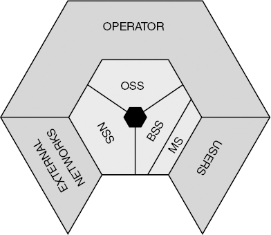
Figure 16.1 Subsystem organization.

Figure 16.2 GSM protocol stacks.
The network and switching subsystem bridges the link between the operator's network and other external networks. (Remember: We have to manage roaming, so we need a mechanism for supporting users as they move out of the home network to other networks—that is, macro mobility management.)
The network and switching subsystem must be able to communicate with the home location register and visitor location register, that is, globally manage mobile users. The base station subsystem and the mobile subsystem look toward the users and manage physical radio resource allocation.
Figure 16.2 shows the protocol interfaces, which are exercised as traffic moves into the network. Call maintenance (CM) looks after communication management—call setup, call maintenance, call clear-down. This is really quite simple in a second-generation wireless network. A call is set up, maintained, and cleared down. The only complication introduced by the radio physical layer is that the call might be dropped because of some problem with the radio channel (the user disappears into a tunnel with no RF coverage) and the call may have inconsistent quality. Other than that, CM is the same whether it's a wireless or wireline connection.
Third-Generation Signaling
Consider, however, how much more complex CM becomes in a third-generation network. We set up a session. The session may need just one physical channel, but we still have to decide on the parameters available for that channel—maximum bit rate, minimum bit rate, required bit error rate, and a non-isochronous or isochronous bit stream. The application layer then requests a second channel. We need to decide on the parameters available for that channel. We now have two channels active for the single user. Note also: If we are using dynamic rate matching, either of these channels can change rate every 10 ms.
Theoretically we may need to support up to six channels per user, and any one channel could be continuously changing its bandwidth quantity and quality metrics. Call maintenance (session maintenance) becomes a far more complex process. For instance, we may also need to be supporting multiple users all co-sharing the same user group channel, all individually needing more or less bandwidth as the session progresses. We then need to clear down the session and find some way of describing the session activity (the session persistency and complexity metrics), so that the network can bill the participants.
Protocol Stack Arrangement
Figure 16.3 shows how the protocol stack is arranged in an existing (2G) handset. Consider that in a 3G network, CM effectively is replaced with a session management (SM) protocol that establishes session properties at the start of a session and adapts to any changes in session property needed as the session progresses.
In a 2G network, the mobility management protocol takes the user information from the SIM (international mobile subscriber identity number) and uses that information to negotiate access to the network, which may be the host network or a visited network—that is, user authentication (AUC) via the Home Location Register (HLR) or Visitor Location Register (VLR).
In a 3G network, the U-SIM holds much more information on the user and the user's right of access:
- Is the user entitled to use multiple channels?
- Does the user have a right of access to virtual storage?
- Does the user have right of access to particular user groups?

Figure 16.3 Mobile station protocol stack.
In addition, session properties will be dependent on the user's hardware and software form factor and functionality:
- Does the user have a high color depth high-resolution display?
- Does the user have a wideband audio coder, CMOS imager, and MPEG4 encoder?
- Does the user have the right to use these capabilities?
- Does the user have end-to-end encryption?
- Does the user have the right to use end-to-end encryption?
- Has the user deposited a key with the trusted third party to provide for lawful interception?
- Does the user have the right to make micro-payments (small purchases)?
- Does the user have the right to make macro-payments (large payments)?
Load Distribution
In a 2G network, radio resource (RR) allocation looks after time slot allocation and RF channel allocation. When a handset accesses a network, it will be authenticated and told which base stations to monitor (a serving base station and up to five handover candidates). If the mobile requests a call, a time slot will be allocated within an RF channel (actually a duplexed spaced RF channel pair for the uplink and downlink). If the network needs to move the handset to another time slot, or to another RF channel, or to another base station, this will be achieved by using the fast associated control channel.
In a 3G network, the RNC will also be looking after load distribution to manage the highly dynamic changes in offered traffic. Load distribution includes the need to move handsets into and out of soft handover involving, as described in earlier chapters, substantial communication between serving and drift RNCs. Radio resource allocation becomes much more complex and much more dynamic and may change continuously as a session progresses.
For example, a change in radio resource allocation in a 2G network occurs because of a handset moving from one cell to another while a call is in progress. This will also happen in a 3G network, but in addition, as a session progresses, OVSF code channel allocation may change every 10 ms on existing allocated channels, and new channels may be added or subtracted from the user's physical layer multimedia multiplex.
The allocation decision may be driven by the application requirement, but whether or not resources are allocated will be driven by whether the network has radio, transmission, and storage resources available, and whether, even if these resources are available, the network wants to make those resources available. It may be that the decision is made to reserve resources in case more important users need them, which means the decision-making process becomes highly dynamic and adaptive, and becomes dependent on multiple technical, operational, and commercial decision criteria.
Just because a user or the user's application has requested a certain allocation of bandwidth and just because a user has a right to a certain allocation of bandwidth does not ensure that the user or application will receive that allocation, either at the beginning of the session or as the session progresses. For instance:
- What happens if the network delivers the application requirement for 90 percent of the session but fails to deliver the application requirement for 10 percent of the session, does the user get a 10 percent rebate?
- How does the user or the application know that the bandwidth allocated has only matched the bandwidth requested for a certain percentage of the session?
- How does the user or the application prove that the performance delivered was not the same as the performance requested; does the network bill for the performance requested or the performance delivered? (Can you guess which one is more likely?)
Somehow this complex performance capture process has to be undertaken (preferably in the user's device), and the failure to perform has to be communicated back to the network to provide the basis for rebate-based billing. We are adding technical and commercial complexity, which, in turn, results in additional signaling complexity.
3G Frame Structure
Referring to Figure 16.3, the last part of the protocol stack in the handset is the LAP Dm protocol that looks after framing between the mobile and the base station—or in GSM, 8 slots in a frame, 26 or 52 frames in a multiframe or multiple multiframes concatenated into superframes, and hyperframes. We described the 3G frame structure in earlier chapters (that is, commonality with GSM at multiframe level). The frame structure in the 3G air interface is actually simpler. The complexity comes from the need to support GSM/IMT2000 intersystem internetwork handover, which requires the handset to be able to compile management reports from both networks and then send those reports back (probably) to the MSC for an internetwork handover decision to be made.
2G Versus 3G Session Management
Figure 16.4 shows the protocol stack in a 2G base station. The base station is in essence a dumb modem that just moves traffic into the network and out from the network to its local flock of handsets. Power control and handover decisions are made by the BSC.

Figure 16.4 Base station protocol stack.
In a 3G or Node B, dynamic OVSF code management needs to be supported in addition to power control and handover management (radio resource allocation). LAPD-M will need to support GSM-to-IMT2000 handovers.
Potentially, the Node B could be the point where packet stream prioritization is undertaken, although present thinking suggests that prioritization and load balancing will be done at the RNC. This is an important philosophical point. In present cellular networks, call/session status information—power levels, serving base stations, bit error rate, and so on—is moved across the same physical channels as our traffic (for example, voice), but it is kept logically separate in its own time slot or its own frame (or both).
Similarly, in a 3G network, status information and measurements share the same physical RF channel but are kept logically separate. As we hit the network, this logical separation between traffic and signaling is maintained. We move the status and management information to the place in the network where a decision has to be communicated back to the device that originated the status and measurement information and to other interested devices (neighboring Node Bs, for example).
If the handset had sufficiently intimate and up-to-date knowledge of the network resources available, it could decide for itself on the most economic/fastest route to be taken through the network and could use that knowledge to describe the required routing trajectory in a packet header. The job of the Node B would be to read the packet header and move the packet stream on into the network on the basis of the packet header instruction. All the signaling effectively stays in band, which means it physically stays with the traffic, even though it may be kept logically separate.
This is not what happens in present wireless networks. Status and management information from the radio layer is extracted by the base station controller and sent on the SS7 signaling path to the MSC. Figure 16.5 shows how signaling is presently arranged in a base station controller.

Figure 16.5 BSC protocol stack.
- DTAP (Data Transfer Application Part) looks outward to the user and the user's device (the handset).
- BSSMAP (Base Station Subsystem Mobile Application Part) looks after the management of the base station serving the user and other handover candidate neighbor base stations.
- SCCP (Signaling Connection Control Part) looks after the management of traffic channels and routers, that is, the physical routing of offered traffic.
- MTP (Mobile Transaction Part) looks after the commercial needs of the offered traffic, determining the following:
- Is the user authenticated?
- Does the user have particular rights of access?
- Has the user roamed from another network?
There is a lot of network control involved here. This implies substantial signaling load, which costs money and introduces delay. Network operators do, however, like to feel in control of their traffic, and this may be regarded as a necessary unavoidable overhead.
Figure 16.6 shows how all this signaling finally ends up in the mobile switch center.
The parts are as follows:
- TCAP (Transaction Capability Application Part) looks after the commercial properties of the traffic—the right of access, the right to be billed for a certain service/quality of service.
- MAP (Mobile Application Part) looks after the housekeeping needed to keep track of a mobile user—the mobility management. Note this is going on the whole time your phone is turned on, whether or not you are making a call. The phone is continuously measuring its serving base station and making the measurement report, which is fed back to the BSC and MSC, so that the MSC knows where the mobile is physically (so traffic can be delivered from and to the mobile) and so that it knows the quality of the radio link presently maintained.
- The ISUP (ISDN User Part) looks after the call setup, call maintenance, call clear-down—that is, ISDN-based call management.

In a 3G network, all these MSC-based functions become substantially more complex. In a 2G network, TCAP just has to decide whether a user has a right of access to a call—a voice circuit. In a 3G network, TCAP has to decide on the traffic properties and hence the required session properties needed for the user:
- Does the network have sufficient resources available?
- Can these resources continue to be made available as the session progresses?
- Are additional participants permitted to join the session, and what are their required session properties?
The MAP part in a 3G network needs to comprehend traffic shedding and load distribution in the radio access network, as well as the mechanics of managing mobile users in a complex network. Because the network is a mixture of GSM and IMT2000, MAP must be able to capture and act on intersystem radio bearer measurements.
ISUP has to look after session-related signaling (as opposed to call-related signaling). ISUP in a wireless network has always been a bit more complicated than a wireline network, because the addition of a radio channel in the communications link means that a call may be terminated unexpectedly or may become unacceptably noisy.
Similarly in session management, the session may terminate or become unacceptably noisy. What has changed, however, is that session properties are now far more dynamic. A call is a call. A voice circuit is established, maintained and cleared down, and billed.
A session is a chameleon, changing its color as the session progresses—becoming more complex, less complex. The application bandwidth and required quality metrics are constantly changing. ISUP has to respond to that constantly changing bandwidth quality requirement, provision the bandwidth, and then qualify whether the bandwidth requirement was or was not fulfilled for the duration of the session. Note also that the signaling has to communicate with other interested or involved networks.
Communications between Networks
Figure 16.7 shows the ISUP link to the Public Switched Telephone Network (PSTN). Consider that there are now between three and six operators in most countries and roughly 100 countries (or separate political entities with their own national communication networks), so there are over 500 cellular networks that have to be capable of talking to each other and to their respective wireline networks. In a 2G network, the information in the HLR and VLR is reasonably simple—a description of the user (SIM identity) and the user's hardware (stored in the Equipment Identity Register).

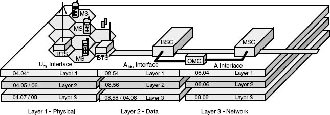
In a 3G network, the information is far more complex—the user's service profile, the user's device hardware and software form factor and functionality, the user's access rights to delivery and storage bandwidth, associated buddy groups and user group configuration, and on and on. Figure 16.8 summarizes the present signaling structure in a wireless network.
The components are as follows:
- The UM interface looks after the link between mobiles and the base station.
- The A-bis interface looks after the link between the base station and base station controller.
- The A interface looks after the link between the base station controller and the MSC.
- The OMC (Operation and Maintenance Center) tracks any hardware failures occurring in the network (and from other related networks) and looks after software-based service platforms.
Why We Need Signaling
Let's summarize why we need signaling:
- Signaling allows network software to make intelligent decisions on the basis of information received from various parts of the network (or other related networks).
- Signaling has a very direct impact on radio and network bandwidth quality. If signaling is poorly implemented, either the wrong decision will be made or the decision will be made too slowly.
- Signaling overhead increases as networks become more complex. Networks become more complex as network density increases. If base stations are closer together and the mobility of users stays the same, then the network will have to manage more handovers.
- If we try to get more performance out of our radio physical layer, we often find our signaling load increases. In a 3G network, we employ soft handover to give us uplink and downlink diversity gain. This substantially increases signaling bandwidth at and between the serving and drift RNC.
- As session complexity increases, signaling complexity increases. If our traffic properties are constantly changing, our signaling has to respond.
- Signaling introduces delay and delay variability. (Remember: We are trying to support static rate matching where channels are added and subtracted on a per-user basis as a session progresses, and we are trying to support dynamic rate matching where channels can change their offered traffic properties—bit rate and channel coding—every 10 ms.
Moving Beyond the Switch
Historically, much of the decision making in a cellular network has been centralized in the switch—20 million lines of software code providing centralized control. This has historically worked well, because the offered traffic has been very deterministic—that is, highly predictable. A request for a call is received with a destination address; we set up the call, maintain the call, clear down the call, and bill the call. Call setup, call maintenance, call clear-down, and call billing is easy. Session setup, session maintenance, session clear-down, and session billing is not so simple.
A mobile switch center behaves very predictably when loaded with predictable traffic, particularly if the traffic is constant rate and constant quality. However, we have said that our per-user traffic mix is now neither constant rate nor constant quality. The quality requirements of our traffic will change dynamically as our traffic mix changes and our session progresses. The object of the whole exercise, however, is to give the user the feeling that he or she is getting a constant-quality user experience, which means at any given moment, we have to provide sufficient radio and network bandwidth quantity and quality such that we avoid compromising the user's application quality (and by implication, application value).
As we discussed in earlier chapters, this may mean adding in extra channel coding, changing modulation state, increasing power on the radio channel, or, in the network, providing a particular routing trajectory to deliver a defined end-to-end delay and delay variability metric. Our network software, therefore, has to be capable of taking highly dynamic decisions on the basis of highly dynamic information often received from multiple destinations. These are decisions that rely on feedback control.
Feedback processes work best. They are fastest in decentralized distributed networks. There is no point in taking very time-dependent decisions on, for example, radio resource allocation, if the signaling path introduces more delay than the decision window can accommodate.
Letting the Handset Make the Decisions
The ultimate logic is to move the decision making into the handset. The handset intuitively knows the properties needed from the radio physical layer and network in order to preserve the application properties being generated by the handset. It is, or should be, possible for the handset to discover available radio and network resources and then to negotiate access to those resources.
It should also be possible to express this bandwidth quality requirement in a packet header. The base station/Node B reads the packet header and obeys the routing instruction contained in the header. The routing decision has already been pre-agreed, which means decision making has been distributed out to the user's device.
In theory, this makes complete sense. In practice, most network operators would be very unwilling to live with the idea of allowing a subscriber or subscriber's application to determine routing options or right of access to delivery or storage bandwidth.
Dealing with SS7 and Existing Switching Architectures
In addition, existing signaling protocols (SS7) and switching architectures (circuit switching) have been tested and refined over many years. They provide very certain end-to-end delivery conditions. In a circuit-switched network, we know what the end-to-end delay will be, and we know what the delay variability will be—very little. This makes it much easier to send a bill to someone and avoids the problem of that user complaining that he or she has not received what he or she was expecting.
The SS7 signaling provides us with a transparent view of a call as it progresses. This is partly because the signaling plane is logically separate from the traffic. Effectively, the signaling is looking down at the traffic below. If we were to embed the signaling at packet header level, we would arguably lose this transparency.
However, if SS7 signaling is to be used to support session management, and if session properties will be constantly changing, this implies very substantial signaling load on the network. This means considerable signaling bandwidth will be absorbed, resulting in occupied bandwidth, which is expensive—the cost of signaling overhead.
Additionally, if the signaling path is physically long, there will be too much hysteresis. The signaling responses will be too slow to adapt to the changing loading conditions—the network software implications of managing audio, image, video, and application streaming—which means the signaling path will introduce delay. If the decisions being taken are complex, the signaling will also introduce delay variability.
Signaling is therefore an important ingredient in network bandwidth quality and session consistency.
Making a Choice
We then have a choice: We can throw away SS7 signaling and circuit switching or adapt SS7 signaling and circuit switching to accommodate complex sessions. As session persistency increases, it becomes increasingly attractive to keep SS7. The longer the session, the more economic out-of-band signaling becomes—and the less attractive in-band packet header-based signaling becomes.
The problem is more the issue of whether to retain the circuit-switching capabilities of existing networks. We have said that circuit switching provides very dependable, very predictable performance, which, when combined with SS7 signaling, provides a very robust basis for billing. It is, however, relatively inflexible and nonoptimum for dealing with highly asynchronous and constantly varying traffic. A circuit switch is essentially a hardware platform with a relatively small amount of software (20 million lines of code). It is fast and efficient, but it is not particularly flexible and not particularly adaptive.
An option is to distribute the hardware functionality closer to the edge of the network. This reduces the signaling load on the network, reduces the signaling delay, increases the speed of decision making, and makes the hardware architecture more adaptive to local loading conditions. This is the thought process behind 3GPP1's inclusion of ATM cell switching as a mechanism for managing asynchronous traffic loading in the radio access network.
Note the difference: In a pure play packet routed network, the handset would define routing priorities needed to support the locally generated application. This would be expressed in the packet header. The software in the router in the Node B and RNC would interpret the packet header and route the packet stream as required and described by the packet header.
In an ATM implementation, routing is pre-agreed, probably for the whole session. Any decisions to be taken while a session progresses will be, typically, whether to add or subtract channels for an individual user or change the properties of these channels. The routing stays the same, and the switching is hardware- rather than software-enabled. This means that this is a distributed hardware switched architecture rather than a distributed software routed architecture—an ATM cell switched network rather than an IP routed network.
It will be less flexible than an IP routed network (which relies on software-based decision making to make decisions based on information contained in individual packet headers), but it will be more predictable in terms of the way it behaves when presented with complex content. This means it is a better solution for complex session management. ATM is however not particularly well suited to supporting complex multiuser-to-multiuser exchanges, particularly if feedback is used to manage access control (available bit rate).
We could, of course, use IP protocols for session management and mobility management, as well as network management, but we need to be sure we can replicate all of the functionality presently available to us from existing signaling solutions. We need to find a precise way of qualifying and quantifying protocol performance, particularly traffic shaping protocol performance.
Summary
As offered traffic becomes more asynchronous, it places more demands on the signaling in the network. The signaling needs to become more responsive. This means we have to qualify the hysteresis implicit in the feedback decision-making processes involved, including the time taken to execute a decision. This is very analogous to some of the design considerations we have at chip level where we have to qualify memory fetch routines and housekeeping routines in a device's microcontroller and memory architecture. At network level, similar decisions are being taken—for example, on bandwidth allocation and access prioritization—but the distances are much greater (sometimes many miles).
It is therefore essential to qualify protocol performance at network level—the subject of our next chapter.