
This chapter covers the following topics:
Security as defined in the 1997 802.11 specification—. Why was Wired Equivalent Privacy (WEP) selected as the encryption algorithm and Open and Shared Key selected as the authentication algorithms?
Security vulnerabilities in the 1997 802.11 standard—. Why is WEP ineffective for encryption and Open and Shared Key ineffective for authentication?
Next generation wireless LAN (WLAN) security enhancements—. What are the new technologies being used to secure 802.11 WLANs?
For developers who have implemented or are currently implementing 802.11 wireless, an alphabet soup of acronyms describe enhanced 802.11 WLAN security. Abbreviations such as 802.1X, EAP, LEAP, PEAP, EAP-TLS, WEP, TKIP, WPA, and AES are common terms in describing 802.11 security. For the network administrator accustomed to dealing with IP and connectivity-oriented technologies, these new security-focused protocols can prove confusing.
Imagine extending a long Ethernet cable from your internal network outside your office and laying it on the ground in the parking lot. Anyone who wants to use your network can simply plug into that network cable. Connecting unsecured WLANs to your internal network has the potential to offer the same opportunity.
802.11-based devices communicate with one another using radio frequencies (RFs) as the carrier signal for data. The data is broadcast from the sender in the hopes that the receiver is within RF range. The drawback to this mechanism is that any other station within range of the RF also receives the data.
Without a security mechanism of some sort, any 802.11 station can process the data sent on a WLAN, as long as that receiver is in RF range. To provide a minimum level of security in a WLAN, you need two components:
A means to decide who or what can use a WLAN—. This requirement is satisfied by authentication mechanisms for LAN access control.
A means to provide privacy for the wireless data—. The requirement is satisfied by encryption algorithms.
As Figure 4-1 depicts, wireless security consists of both authentication and encryption. Neither mechanism alone is enough to secure a wireless network.

The 802.11 specification defines Open and Shared Key authentication and WEP to provide device authentication and data privacy, respectively. The Open and Shared Key algorithms both rely on WEP encryption and possession of the WEP keys for access control. Because of the importance of WEP in 802.11 security, the following section focuses on the basics of encryption and ciphers in general.
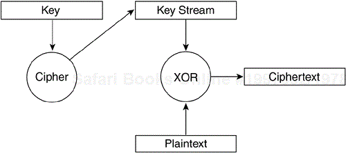
Data encryption mechanisms are based on cipher algorithms that give data a randomized appearance. Two type of ciphers exist:
Stream ciphers
Block ciphers
Both cipher types operate by generating a key stream from a secret key value. The key stream is mixed with the data, or plaintext, to produce the encrypted output, or ciphertext. The two cipher types differ in the size of the data they operate on at a time.
A stream cipher generates a continuous key stream based on the key value. For example, a stream cipher can generate a 15-byte key stream to encrypt one frame and a 200-byte key stream to encrypt another. Figure 4-2 illustrates stream cipher operation. Stream ciphers are small and efficient encryption algorithms and as a result do not incur extensive CPU usage. A commonly used stream cipher is RC4, which is the basis of the WEP algorithm.
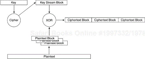
A block cipher, in contrast, generates a single encryption key stream of a fixed size. The plaintext is fragmented into blocks, and each block is mixed with the key stream independently. If the plaintext block is smaller than the key stream block, padding is added to the plaintext block to make it the appropriate size. Figure 4-3 illustrates block cipher operation. The fragmentation process, in addition to other aspects of block cipher encryption, causes the block cipher to incur a larger CPU processing penalty than would a stream cipher. As a result, block cipher operation decreases the effective throughput of a device.
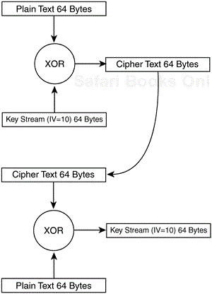
The process of encryption described here for stream ciphers and block ciphers is known as Electronic Code Book (ECB) encryption mode. ECB mode encryption has the characteristic that the same plaintext input always generates the same ciphertext output. The input plaintext always produces the same ciphertext. This factor is a potential security threat because eavesdroppers can see patterns in the ciphertext and start making educated guesses about the original plaintext.
Some encryption techniques can overcome this issue:
Initialization vectors
Feedback modes
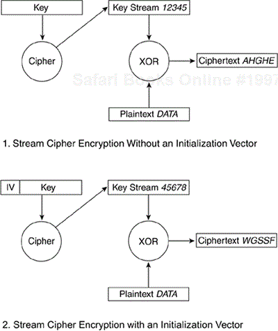
An initialization vector (IV) is a number added to the key, which has the end result of altering the key stream. The IV is concatenated to the key before the key stream is generated. Every time the IV changes, so does the key stream. Figure 4-4 shows two scenarios. The first is stream cipher encryption without the use of an IV. In this case, the plain text DATA when mixed with the key stream 12345 always produces the ciphertext AHGHE. The second scenario shows the same plaintext mixed with the IV augmented key stream to generate different ciphertext. Note that the ciphertext output in the second scenario is different from the ciphertext output from the first. The 802.11 world recommends that you change the IV on a per-frame basis. This way, if the same frame is transmitted twice, it's highly probable that the resulting ciphertext is different for each frame.
The 802.11 specification provides data privacy with the WEP algorithm. WEP is based on the RC4 symmetric stream cipher. The symmetric nature of RC4 requires that matching WEP keys, either 40 or 104 bits in length, must be statically configured on client devices and access points (APs). WEP was chosen primarily because of its low computational overhead. Although 802.11-enabled PCs are common today, this situation was not the case back in 1997. The majority of WLAN devices were application-specific devices (ASDs). Examples of ASDs include barcode scanners, tablet PCs, and 802.11-based phones. The applications that run on ASDs generally do not require much computational power, so as a result, ASDs have meager CPUs. WEP is a simple-to-implement algorithm that you can write in as few as 30 lines of code, in some cases. The low overhead incurred by WEP made it an ideal encryption algorithm to use on ASDs.
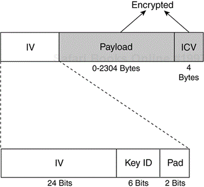
To avoid the ECB mode of encryption, WEP uses a 24-bit IV, which is concatenated to the key before being processed by the RC4 cipher. Figure 4-5 shows a WEP-encrypted frame, including the IV.
The IV must change on a per-frame basis to avoid IV collisions. IV collisions occur when the same IV and WEP key are used, resulting in the same key stream being used to encrypt a frame. This collision gives attackers a better opportunity to guess the plaintext data by seeing similarities in the ciphertext. The point of using an IV is to prevent this scenario, so it is important to change the IV often. Most vendors offer per-frame IVs on their WLAN devices.
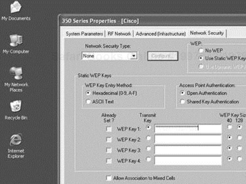
The 802.11 specification requires that matching WEP keys be statically configured on both client and infrastructure devices. You can define up to four keys on a device, but you can use only one at a time for encrypting outbound frames. Figure 4-6 shows a Cisco Aironet client configuration screen for WEP configuration.
WEP encryption is used only on data frames and during Shared Key authentication. WEP encrypts the following fields of an 802.11 data frame:
The data or payload
The integrity check value (ICV)
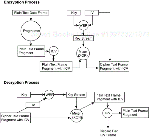
All other fields are transmitted without encryption. The IV must be sent unencrypted within the frame so that the receiving station can use it to properly decrypt the payload and ICV. Figure 4-7 details the process for encryption, transmission, receipt, and decryption of a WEP encrypted data frame.
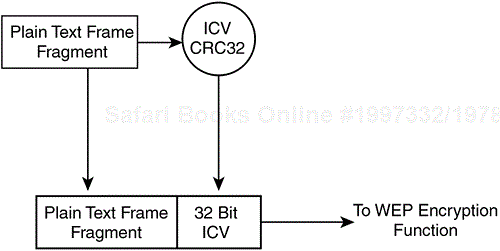
In addition to data encryption, the 802.11 specification provides for a 32-bit value that functions as an integrity check for the frame. This check tells the receiver that the frame has arrived without being corrupted during transmission. It augments the Layer 1 and Layer 2 frame check sequences (FCSs), which are designed to check for transmission-related errors.
The ICV is calculated against all fields in the frame using a cyclic redundancy check (CRC)-32 polynomial function. The sender calculates the values and places the result in the ICV field. The ICV is included in the WEP-encrypted portion of the frame, so it is not plainly visible to eavesdroppers. The frame receiver decrypts the frame, calculates an ICV value, and compares what it calculates against what has arrived in the ICV field. If the values match, the frame is considered to be genuine and untampered with. If they don't match, the frame is discarded. Figure 4-8 diagrams the ICV operation.
The 802.11 specification stipulates two mechanisms for authentication of WLAN clients:
Open authentication
Shared Key authentication
Open authentication is a null authentication algorithm. The AP grants any request for authentication. It might sound pointless at first to have such an algorithm defined, but Open authentication has its place in 802.11 network authentication. The requirements for authentication allow devices to quickly gain access to the network.
Access control in Open authentication relies on the preconfigured WEP key on the client and AP. The client and AP must have matching WEP keys to enable them to communicate. If the client and AP do not have WEP enabled, there is no security in the BSS. Any device can join the BSS and all data frames are transmitted unencrypted.
After Open authentication and the association process, the client can begin transmitting and receiving data. If the client is configured with a key that differs from the key on the AP, the client will be unable to encrypt or decrypt data frames correctly, and the frames will be discarded by both the client and the AP. This process essentially provides a means of controlling access to the BSS. It is illustrated in Figure 4-9.

Unlike Open authentication, Shared Key authentication requires that the client station and the AP have WEP enabled and have matching WEP keys. The following summarizes the Shared Key authentication process:
The client sends an authentication request for Shared Key authentication to the AP.
The AP responds with a cleartext challenge frame.
The client encrypts the challenge and responds back to the AP.
If the AP can correctly decrypt the frame and retrieve the original challenge, the client is sent a success message.
The client can access the WLAN.
The premise behind Shared Key authentication is similar to that of Open authentication with WEP keys as the access control means. The client and AP must have matching keys. The difference between the two schemes is that the client cannot associate in Shared Key authentication unless the correct key is configured. Figure 4-10 shows the Shared Key authentication process.

MAC address authentication is not specified in the 802.11 specification, but it is supported by many vendors. MAC address authentication verifies the client's MAC address against a locally configured list of allowed addresses or against an external authentication server, as shown in Figure 4-11. MAC authentication augments the Open and Shared Key authentications provided by 802.11, potentially reducing the likelihood of unauthorized devices accessing the network. For example, a network administrator might want to limit a particular AP to just three specific devices. If all stations and APs in the BSS have the same WEP keys, it is difficult to use Open or Shared Key authentication to facilitate this scenario. The administrator can configure MAC address authentication to augment 802.11 authentication.

The prior section detailed how 802.11 authentication and encryption operates. It is no secret that security in the 802.11 specification is flawed. Not long after the ratification of 802.11, a number of published papers pinpointed vulnerabilities in 802.11 authentication and WEP encryption.
Open authentication provides no way for the AP to determine whether a client is valid. This lack is a security vulnerability if WEP encryption is not implemented in a WLAN. Even with static WEP enabled on the client and AP, Open authentication provides no means of determining who is using the WLAN device. An authorized device in the hands of an unauthorized user is just as much a network security threat as providing no security at all!
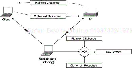
Shared key authentication requires the client to use a preshared WEP key to encrypt challenge text sent from the AP. The AP authenticates the client by decrypting the shared-key response and validating that the challenge text is the same.
The process of exchanging the challenge text occurs over the wireless link and is vulnerable to a known plaintext attack. This vulnerability with Shared Key authentication relies on the mathematical principal behind encryption. Earlier in this chapter, encryption was defined as plaintext mixed with a key stream to produce ciphertext. The mixing process is a binary mathematical function known as an exclusive OR (XOR). If plaintext is mixed with corresponding ciphertext, the result of the function is the key stream for the WEP key and IV pair, as shown in Figure 4-12.
An eavesdropper can capture both the plaintext challenge text and the ciphertext response. By simply running the values through an XOR function, an eavesdropper has a valid key stream. The eavesdropper can then use the key stream to decrypt frames matching the same size as the key stream, given that the IV used to derive the key stream is the same as the encrypted frame. Figure 4-13 illustrates how an attacker can eavesdrop on a Shared Key authentication and derive the key stream.
MAC addresses are sent unencrypted in all 802.11 frames, as required by the 802.11 specification. As a result, WLANs that use MAC authentication are vulnerable to an attacker undermining the MAC authentication process by spoofing a valid MAC address.
MAC address spoofing is possible in 802.11 network interface cards (NICs) that allow the universally administered address (UAA) to be overwritten with a locally administered address (LAA). The UAA is the MAC address that is hard-coded on the NIC by the manufacturer. An attacker can use a protocol analyzer to determine a valid MAC address in the BSS and an LAA-compliant NIC to spoof the valid MAC address.
The most compelling and damaging vulnerability to 802.11 was delivered by three cryptanalysts, Fluhrer, Mantin, and Shamir. In their paper, they determined that you could derive a WEP key by passively collecting particular frames from a WLAN.
The vulnerability surrounds how WEP has implemented the key scheduling algorithm (KSA) from the RC4 stream cipher. A number of IVs (referred to as weak IVs) can reveal key bytes after statistical analysis. Researchers at AT&T and Rice University as well as the developers of the AirSnort application implemented this vulnerability and verified that you can derive WEP keys of either 40- or 104-bit key length after as few as 4 million frames. For high usage 802.11b WLANs, that can translate to roughly one hour until a 104-bit WEP key is derived. This vulnerability renders WEP ineffective as a mechanism to provide data privacy.
The attack is a passive attack, where an attacker simply eavesdrops on a BSS and collects transmitted frames. Unlike the Shared Key authentication vulnerability, the Fluhrer, Mantin, and Shamir attack can derive the actual WEP key, not just the key stream. This information allows the attacker to access the BSS as an authenticated device, unbeknownst to network administrators.
As if this attack was not enough, a second class of attacks on WEP have been theorized but never practically implemented. These inductive attacks leverage the same principle used for the Shared Key authentication vulnerability: a known plaintext and corresponding ciphertext used to derive a key stream.
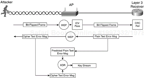
As stated previously, a derived key stream is only useful to decrypt frames for a given IV and WEP key pair and for a specific length. Ideally, an attacker endeavors to collect as many of these key streams as possible to build a key-stream database to subvert the network and decrypt frames. In WLANs where Shared Key authentication is not used, frame bit flipping attacks allow an attacker to derive large numbers of key streams in a short amount of time.
Frame bit flipping attacks rely on the weakness of the ICV. The ICV is based on the CRC-32 polynomial function. This function is ineffective as a means of message integrity. Mathematical properties of the CRC-32 function allow a frame to be tampered with and the ICV value to be modified without the original contents of the frame being known.
Although the data payload size can vary by frame, many elements in 802.11 data frames remain constant and in the same bit position. The attacker leverages this fact and tampers with the payload portion of the frame to modify the higher-layer packet. The process for a bit flipping attack follows (see also Figure 4-14):
The attacker captures a frame from the WLAN.
The attacker flips random bits in the data payload of the frame.
The attacker modifies the ICV (detailed later).
The attacker transmits the modified frame.
The receiver (either a client or the AP) receives the frame and calculates the ICV based on the frame contents.
The receiver compares the calculated ICV with the value in the ICV field of the frame.
The receiver accepts the modified frame.
The receiver forwards the frame to an upper-layer device (a router or host PC).
Because bits are flipped in the Layer 3 packet, the Layer 3 checksum fails.
The receiver IP stack generates a predictable error.
The attacker sniffs the WLAN looking for the encrypted error message.
Upon receiving the error message, the attacker derives the key stream, as with the IV replay attack.
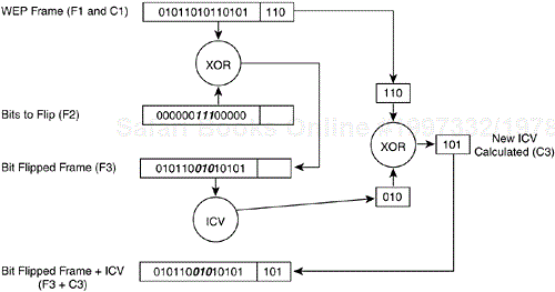
The basis for this attack is the failure of the ICV. The ICV is in the WEP-encrypted portion of the frame, so how is the attacker able to modify it to match the bit flipped changes to the frame? Figure 4-15 illustrates the process of actually flipping bits and changing the ICV:
A given frame (F1) has an ICV (C1). (See Figure 4-15.)
A new frame is generated (F2) with the same length as F1 with bits set.
Frame F3 is created by XORing F1 and F2.
ICV C3 is generated by XORing C1 and C2.
The 802.11 specification does not specify key-management mechanisms. Although not a specific vulnerability, WEP is defined to support only static, preshared keys. Because 802.11 authentication authenticates a device and not the user of the device, the loss or theft of a wireless adapter becomes a security issue for the network. This issue presents network administrators with the tedious task of manually rekeying all wireless devices in the network when the existing key is compromised because an adapter was lost or stolen.
This risk might be acceptable for small deployments where managing user devices is a simple task. Such a prospect is not scalable for medium and large deployments where the number of wireless users can reach into the thousands. Without a mechanism to distribute or generate keys, administrators must keep close tabs on wireless NIC whereabouts.
The WLAN industry recognized the vulnerabilities in 802.11 authentication and data privacy. To provide users with a secure WLAN solution that is scalable and manageable, the IEEE has augmented 802.11 security by developing enhancements to 802.11 authentication and encryption. The changes are being incorporated into the 802.11i draft standard. To date, the 802.11i draft has not been passed as a standard, so the Wi-Fi Alliance has put together an subset of the components of 802.11i called Wi-Fi Protected Access (WPA). This section details and explains 802.11i and WPA components.
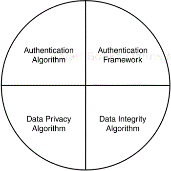
Although this chapter has detailed 802.11 security as a combination of Open/Shared Key authentication and WEP encryption so far, many mistakenly believe WEP to be the only component to WLAN security. Wireless security actually consists of four facets:
The authentication framework—. This facet is the mechanism that accommodates the authentication algorithm by securely communicating messages between the client, AP, and authentication server.
The authentication algorithm—. This facet is the algorithm that validates the user credentials.
The data privacy algorithm—. This facet provides data privacy across the wireless medium for data frames.
The data integrity algorithm—. This facet provides data integrity across the wireless medium to ensure to the receiver that the data frame was not tampered with.
These facets are illustrated in Figure 4-16.
The authentication framework in 802.11 is the 802.11 authentication management frame. The authentication frame facilitates Open and Shared Key authentication algorithms, yet the frame itself does not possess the ability to authenticate a client. Because the shortcomings of 802.11 authentication have already been highlighted, it is important to understand what is needed to provide secure authentication in a WLAN.
802.11 is missing some key components to provide effective authentication:
Centralized, user-based authentication
Dynamic encryption keys
Encryption key management
Mutual authentication
User-based authentication is critical for network security. Device-based authentication, such as Open or Shared Key authentication, does not prevent unauthorized users from using authorized devices. Also, logistical issues, such as lost or stolen devices and employee termination, can force network administrators to manually rekey all 802.11 APs and clients. Centralized, user-based management via an authentication, authorization, and accounting (AAA) server, such as a RADIUS, lets you allow or disallow specific users, regardless of the specific devices they use.
The requirement for user-based authentication has a positive side effect: user-specific encryption keys. Authentication types that support the creation of dynamic encryption keys fit well into the WLAN security and management model. Per user, dynamic keys relieve the network administrator from having to statically manage keys. Encryption keys are dynamically derived and discarded as the user authenticates and disconnects from the network. Should you need to remove a user from the network, you only need to disable her account to prevent her access.
Mutual authentication is two-way authentication. The “two-way” nature comes from not only the network authenticating the client, but also the client authenticating the network. In Open and Shared Key authentication, the AP or network authenticates the client. The client does not know for sure that the AP or network is valid because no mechanism is defined in the 802.11 specification to allow the client to authenticate the network. As a result, a rogue AP or rogue client station can pose as a valid AP and subvert the data on the client's machine. Figure 4-17 diagrams one-way authentication versus mutual authentication.

802.11 WLAN vendors and the IEEE understand the need to augment and replace existing security mechanisms, both in authentication and encryption. Work is currently underway in task group I of the 802.11 working group, and after the changes are complete, the security specifications will be ratified as the 802.11i specification.
The IEEE has addressed the shortcomings of 802.11 authentication by incorporating the 802.1X authentication framework. 802.1X itself is an IEEE standard that provides all 802 link layer topologies with extensible authentication, normally seen in higher layers. 802.1X is based on a Point-to-Point Protocol (PPP) authentication framework known as the Extensible Authentication Protocol (EAP). In oversimplified terms, 802.1X encapsulates EAP messages for use at Layer 2. 802.11i incorporates the 802.1X authentication framework requiring its use for user-based authentication. Figure 4-18 illustrates 802.1X with respect to authentication algorithms and 802 link layer topologies.
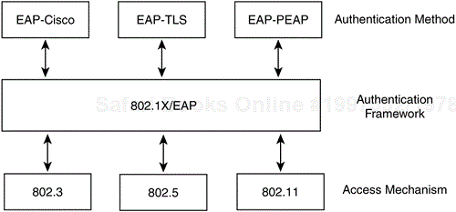
EAP (RFC 2284) and 802.1X do not mandate the use of any specific authentication algorithm. The network administrator can use any EAP-compliant authentication type for either 802.1X or EAP authentication. The only requirement is that both the 802.11 client (known as the supplicant) and the authentication server support the EAP authentication algorithm. This open and extensible architecture lets you use one authentication framework in differing environments, where each environment may use a different authentication type. Examples of EAP authentication types include the following:
EAP-Transport Layer Security (EAP-PEAP)—. Operates similar to Secure Sockets Layer (SSL) at the link layer. Mutual authentication is accomplished via server-side digital certificates used to create a SSL tunnel for the client to securely authenticate to the network.
EAP-Message Digest 5 (EAP-MD5)—. Similar to the Challenge Handshake Authentication Protocol (CHAP), EAP-MD5 provides a password based, one-way authentication algorithm.
EAP-Cisco—. Also known as LEAP, EAP-Cisco was the first EAP type defined specifically for use in WLANs. EAP-Cisco is a password-based, mutually authenticating algorithm.
802.1X authentication requires three entities:
The supplicant—. Resides on the WLAN client
The authenticator—. Resides on the AP
The authentication server—. Resides on the RADIUS server
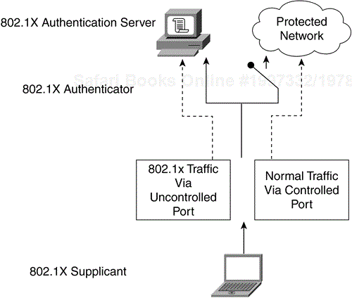
These entities are logical software components on network devices. With respect to 802.11, the authenticator creates a logical port per client device, based on the client's association ID (AID). This logical port has two data paths: uncontrolled and controlled. The uncontrolled data path allows all 802.1X authentication traffic through to the network. The controlled data path blocks normal network traffic until successful client authentication occurs. Figure 4-19 shows the logical ports of an 802.1X authenticator.
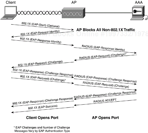
802.1X message exchanges vary, depending on the authentication algorithm, but the general message exchange is as follows:
The client supplicant becomes active on the medium and associates to the AP authenticator.
The authenticator detects the client association and enables the supplicant's port. It forces the port into an unauthorized state so only 802.1X traffic is forwarded. All other traffic is blocked.
The client may send an EAP-Start message, although client initiation is not required. Figure 4-20 diagrams the 802.1X message exchange.
The authenticator replies with an EAP-Request Identity message back to the supplicant to obtain the client's identity.
The supplicant's EAP-Response packet containing the client's identity is forwarded to the authentication server. The value of the identity response varies by EAP type, but in general, only the username or equivalent is sent, not any form of shared secret, such as a password.
The authentication server is configured to authenticate clients with a specific authentication algorithm. Currently, 802.1X for 802.11 LANs does not stipulate a specific algorithm to use.
Depending on the EAP authentication algorithm-specific credential exchange outcome, the last 802.1X-specific message is a RADIUS-ACCEPT or RADIUS-REJECT packet from the authentication server to the AP.
Upon receiving the ACCEPT packet, the authenticator transitions the client's port to an authorized state, and traffic may be forwarded.
802.1X does not specify nor mandate any particular EAP authentication algorithm.
802.11i and WPA provide a mechanism for authentication algorithms to communicate between client, AP, and authentication server, via the 802.1X authentication framework. Neither 802.11i nor WPA mandate the use of specific authentication algorithm, but both recommend the use of an algorithm that supports mutual authentication, dynamic encryption key generation, and user-based authentication. Figure 4-21 highlights the messages exchanged between the client, AP, and AAA server, but it might be easier to conceptualize the process with a specific example. This section highlights the operation of EAP-Cisco. EAP-Cisco (more commonly known as Cisco LEAP) is a simple and effective algorithm that is specifically designed for use in WLANs.

Figure 4-21 depicts EAP-Cisco operation. The following list describes each transaction in greater detail.
The client becomes active on the medium and sends an 802.1X-encapsulated EAP-Start message to the AP.
The AP blocks the client's port, allowing only 802.1X traffic through to the network.
The AP sends an 802.1X-encapsulated EAP-Request Identity message to the client.
The client replies with an 802.1X-encapsulated EAP-Response containing the username of the client.
The AP forwards the username to the authentication server encapsulated in a RADIUS ACCESS-REQUEST packet.
The RADIUS server generates an EAP-Cisco challenge message and sends it to the client (via the AP) encapsulated in a RADIUS ACCESS-RESPONSE packet.
The AP forwards the EAP-Cisco challenge to the client encapsulated in an 802.1X frame.
The client processes the challenge through the EAP-Cisco algorithm and sends a challenge response back to the RADIUS server via the AP.
The AP encapsulates the EAP-Cisco challenge response in a RADIUS ACCESS-REQUEST packet and forwards it to the RADIUS server.
The client sends an EAP-Cisco challenge to the RADIUS server (via the AP) to authenticate the network. The challenge is encapsulated in an 802.1X frame.
The AP encapsulates the EAP-Cisco challenge in a RADIUS ACCESS-REQUEST packet.
The RADIUS server sends the EAP-Cisco challenge response back to the client (via the AP) encapsulated in a RADIUS ACCESS-RESPONSE packet.
The AP encapsulates the EAP-Cisco challenge response in an 802.1X frame and sends it to the client.
The RADIUS server generates a dynamic encryption key based on the user's pass-word and some session-specific information.
The client generates the same dynamic encryption key. The client is capable of locally generating the same key because it has access to the same information.
The RADIUS server sends the key to the AP encapsulated in a RADIUS ACCEPT packet. The RADIUS ACCEPT packet indicates to the AP that authentication was successful.
The AP installs the dynamic key for the specific client, encapsulates an EAP-Success message in an 802.1X frame, and forwards the message to the client.
The AP transitions the client's port into a forwarding state.
The client opens its port (assuming successful mutual authentication).
EAP-Cisco is a proprietary authentication algorithm that runs atop an open authentication framework. For this reason, details of the EAP-Cisco algorithm (such as challenge generation and challenge response contents, as well as encryption key derivation) are unavailable for public consumption. EAP-Cisco covers the requirements set forth for secure user authentication in WLAN by including the following:
User-based authentication
Mutual authentication
Dynamic encryption keys
Should you need to remove a specific user from the network, you disable only his account from the centralized authentication server. This process prevents the user from successfully authenticating and generating a valid dynamic encryption key.
The encryption vulnerabilities in WEP present 802.11 vendors and the IEEE with a predicament: How can you fix 802.11 encryption without requiring a complete replacement of AP hardware or client NICs?
The IEEE answered this question with the Temporal Key Integrity Protocol (TKIP) as part of 802.11i (and WPA). TKIP uses many key functions of WEP to maintain client investment in existing 802.11 equipment and infrastructure but fixes several of the vulnerabilities to provide effective data-frame encryption. The key enhancements contained with TKIP are
The Fluhrer, Mantin, and Shamir paper describes the vulnerability of RC4 as it is implemented in WEP. Attacks that leverage this weak IV vulnerability, such as AirSnort, rely on collecting several data frames with encrypted data using weak IVs. The easiest way to mitigate these attacks is to change the WEP key used between the client and AP before an attacker can collect enough frames to derive key bytes.
The IEEE has adopted a scheme known as per-frame keying. (It is also known as per-packet keying and fast packet keying.) The premise behind per-frame keying is that the IV, the transmitter MAC address, and the WEP key are processed together via a two-phase mixing function. The output of the function matches the standard 104-bit WEP key and 24-bit IV.
The IEEE is also proposing that the 24-bit IV be increased to a 48-bit IV. Subsequent sections detail why the IV expansion is necessary. Figure 4-22 depicts a sample 48-bit IV and how the IV is broken apart for use in per-frame keying.

The following steps outline the process for per-frame keying:
The base WEP key (derived from 802.1X authentication) is mixed with the most significant 32 bits (a 32-bit number ranges from 0 to 4,294,967,295) of the 48-bit IV and the MAC address of the transmitter. The output is called a phase 1 key. This process allows the phase 1 key to be cached and also places directionality into the key (see Figure 4-23).
The phase 1 key is again mixed with the IV and the transmitter MAC address to yield the per-frame key.
The IV used for frame transmission is only 16 bits (a 16-bit number ranges from 0 to 65,535). The remaining 8 bits is a fixed value used as a placeholder.
The per-frame key is used to WEP-encrypt the data frame.
When the 16-bit IV space is exhausted, the phase 1 key is discarded, and the 32 most significant bits are incremented by 1. (If the phase 1 IV was 12, it increments to 13.)
The per-frame key is recalculated as in Step 2.

The per-frame key is only valid when the 16-bit IV values have not been used. If an IV value is used twice, an IV collision occurs, which gives attacks an opportunity to derive the key stream. To avoid IV collision, the phase 1 key is recalculated by incrementing the most significant 32 bits of the IV by 1 and recalculating the per-frame key.
NOTE
Per-frame keying mitigates statistical attacks (such as the AirSnort) against the per-frame key as long as the per-frame key/IV pair remain unique.
The following steps illustrate the per-frame keying operation in detail:
The device initialized the IV to 0. The binary representation of the IV is 000000000000000000000000000000000000000000000000.
The first (most significant) 32 bits of the IV (in this case, the first 32 0), is mixed with 802.1X-derived key (a 128-bit value) and the transmitter MAC address (a 48-bit value) to produce the phase 1 key (an 80-bit value).
The phase 1 key is mixed with the first (most significant) 32 bits of the IV and the transmitter MAC address again to yield a 128-bit per-frame key output, of which is the first 16 bits is the IV (16 0s).
The IV for the per-frame key increments by 1. (The first IV is 16 0s, the subsequent is 15 0s and a 1, and so on, until all 16 bits are 1.)
After the per-frame IV is exhausted, the phase 1 IV (32 bits) is incremented by 1. (It is now 31 0s and a 1, 00000000000000000000000000000001.)
The next logical questions is “Will this mechanism ever cause an IV collision?” The answer is yes, but the real issue is when. Given that the maximum forwarding rate for an 802.11b device is roughly 1000 frames per second, the 16-bit frame IV exhausts after 65 seconds (216 frames/1000 frame per second).
There are 232 possible phase 1 IVs (the first 32 bits of the 48-bit IV), which is 4,294,967,296 possible values. Each one of these values increments after the 16-bit frame IV exhausts (which is every 65 seconds), so the entire 48-bit IV exhausts after 65 seconds * 4,294,967,296, about 8852 years. Unless the administrator forces a reauthentication, a rekey is not realistically required to avoid IV collisions.
This algorithm strengthens WEP to the point that most known attacks are mitigated without having to replace existing hardware. It is important to note that this algorithm (and TKIP as a whole) is designed to patch the holes in WEP and 802.11 authentication. It offers weak algorithms in lieu of hardware replacement. The next generation of 802.11 equipment should support TKIP, but WEP/TKIP should be phased out in favor of an algorithm with a higher degree of cryptographic strength, such as Advanced Encryption Standard (AES) (discussed later).
The MIC is a feature used to augment the ineffective ICV of the 802.11 standard. The MIC solves vulnerabilities such as the frame tampering/bit flipping attacks discussed earlier in the chapter. The IEEE has proposed a specific algorithm, known as Michael, to augment the ICV function in the encryption of 802.11 data frames.
The MIC has a unique key that differs from the key used to encrypt data frames. This unique key is mixed with the destination MAC address and the source MAC address from the frame as well as the entire unencrypted data payload portion of the frame. Figure 4-24 illustrates the Michael MIC algorithm.

The entire TKIP encryption mechanism is detailed in the following steps:
The per-frame keying algorithm derives a per-frame key (see Figure 4-25).
The MIC algorithm generates a MIC for the entire frame.
The frame is fragmented according to MAC settings for fragmentation.
The per-frame key encrypts the frame fragments.

Similar to the TKIP encryption process (see Figure 4-26), the following steps detail the TKIP decryption process:
The phase 1 key is precomputed.
The phase 2 per-frame key is calculated based on the IV from the incoming WEP frame fragment.
If the IV arrives out of order, the frame is discarded.
If the ICV fails, the frame is discarded.
The decrypted frame fragments are reassembled into the original data frame.
The receiver calculates the MIC value and compares it to what is in the MIC field of the frame.
If the values match, the frame is processed by the receiver.
If the values do not match, the frame has a MIC failure and the receiver initiates MIC countermeasures.

The MIC countermeasures consist of the following tasks performed by the receiver:
The receiver deletes the existing keys for the association.
The receiver logs the issue as a security-relevant matter.
The associated client from which the faulty frame was received cannot associate and authenticate for a period of 60 seconds to slow down the attacker.
If the client received the faulty frame, the client drops any non-802.1X frames.
The client also requests a new key.
The per-frame keying and MIC discussion has mentioned two primary keys: the encryption key and the MIC key. No discussion covered how the keys are generated or sent from client to AP and vice versa. The next section deals with proposed 802.11 key management.
802.1X and EAP authentication algorithms can provide the RADIUS server and client with dynamic, user-based keys. But the key that is derived during authentication is not the key used for frame encryption or for message integrity. In 802.11i and WPA, it is known as the master key, used to derive these other keys. Figure 4-27 depicts the 802.11 unicast key hierarchy.
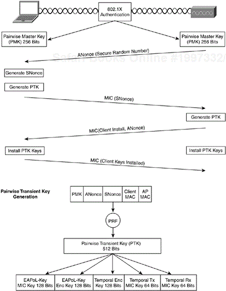
The mechanism for generating the encryption keys is known as the four-way handshake. The following steps summarize the four-way handshake:
The client and AP install the dynamic key (known as the pairwise master key or PMK) derived from 802.1X authentication.
The AP sends the client a secure random number, known as the authenticator nonce (ANonce) via an 802.1X EAPoL-Key message.
The client locally generates a secure random number, known as the supplicant nonce (SNonce).
The client generates the pairwise transient key (PTK) by combining the PMK, SNonce, ANonce, Client MAC, AP MAC, and an initialize string. The MAC addresses are ordered, with the low-order MAC preceding the high-order MAC. This process ensures that the client and AP order the MACs in the same manner.
The combined value is run through a pseudo random function (PRF) to generate a 512-bit PTK.
The client sends the SNonce it generated in Step 3 to the AP via an 802.1X EAPoL-Key message, protected with the EAPoL-Key MIC key.
The AP uses the SNonce to calculate the PTK in the same manner as the client.
The AP uses the derived EAPoL-Key MIC key to validate the integrity of the client's message.
The AP sends an EAPoL-Key message indicating that the client should install the PTK and its ANonce, protected with the EAPoL-Key MIC Key. This step allows the client to validate that the ANonce it received in Step 2 is valid.
The client sends an EAPoL-Key message protected with the EAPoL-Key MIC key, indicating the keys have been installed.
The PMK and PTK derive keys are unicast in nature. They only encrypt and decrypt unicast frames, and they are assigned to a single user. Broadcast frames require a separate key hierarchy because using the unicast keys would dramatically increase network traffic. The AP (the only entity in a BSS that can send broadcast or multicast traffic) would have to send the same broadcast or multicast frame to each user encrypted with the appropriate per-frame keys.
Broadcast and multicast frames use the group key hierarchy. The group master key (GMK) is at the top of the hierarchy and is derived on the AP. GMK derivation is based on a PRF that outputs a 256-bit GMK. The inputs into the PRF-256 are a cryptographically secure random number (or nonce), a text string, the MAC address of the AP, and the time in network time protocol (NTP) format. Figure 4-28 illustrates the group key hierarchy.
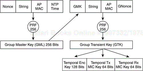
The GMK, a text string, the AP MAC address, and the GNonce (a value taken from the AP key counter) are concatenated and processed via a PRF, which outputs a 256-bit group transient key (GTK). The GTK is divided into a 128-bit broadcast/multicast encryption key, a 64-bit transmit MIC key, and a 64-bit MIC receive key. The keys encrypt and decrypt broadcast and multicast frames in exactly the same manner as unicast keys derived from the PMK.
The client is updated with the group encryption keys via an EAPoL-Key message. The AP sends the client the EAPoL message encrypted with the client's unicast encryption key. The group keys are purged and regenerated every time a station disassociates or deauthenticates the BSS. Also, if a MIC failure occurs, one of the countermeasures is to purge all the keys for the impacted receiver, and this purge includes the group keys.
WEP encryption and 802.11 authentication are known to be weak. The IEEE and WPA are enhancing WEP with TKIP and providing robust authentication options with 802.1X to make 802.11-based WLANs secure. At the same time, the IEEE is also looking to stronger encryption mechanisms. The IEEE has adopted the AES to the data-privacy section of the proposed 802.11i standard. WPA does not include support for AES encryption. Later versions of WPA are likely to be released to align with 802.11i for interoperable AES encryption support.
The AES is the next generation encryption function approved by the National Institute of Standards and Technology (NIST). NIST solicited the cryptography community for new encryption algorithms. The algorithms had to be fully disclosed and available royalty free. Candidates were judged on cryptographic strength as well as practical implementation. The finalist, and the adopted method, is also known as the Rijndael algorithm. Like most ciphers, AES requires a feedback mode to avoid the risks associated with ECB mode. The IEEE has designed a mode for AES tailored to the needs of WLANs. The mode is known as Cipher Block Chaining Counter Mode (CBC-CTR) with Cipher Block Chaining Message Authenticity Check (CBC-MAC), collectively known as AES-CCM. CCM mode is the combination of CBC-CTR encryption mode and the CBC-MAC message authenticity algorithm. The functions are combined to provide encryption and message integrity in one solution.
CBC-CTR encryption operates by using a counter to augment the key stream. The counter increments by 1 after encrypting each block. This process provides a unique key stream for each block. The plaintext frame is fragmented into 16-byte blocks. As each block is encrypted, the counter increments by 1, until all blocks are encrypted. The counter resets for each new frame.
CBC-MAC operates by using the result of CBC encryption over frame length, destination address, source address, and data. The resulting 128-bit output is truncated to 64 bits for use in the transmitted frame.
AES-CCM uses cryptographically known functions but has the overhead of requiring two operations for encryption and message integrity. This process is computationally expensive and adds a significant amount of overhead to the encryption process.
802.11 authentication and encryption as defined in the 1997 standard is deeply flawed. The authentication can be broken, as can the WEP encryption, in little time. TKIP promises to fix WEP and authentication in the short term, and 802.1X and AES promise to be a long-term answer to wireless security.
This chapter gave you insight into how to secure a WLAN and remove the obscurity surrounding wireless security in general. The key to deploying WLANs is deploy them as securely as possible while providing the best possible user experience.