
Understanding how the 802.11 protocol operates, the behavior of mobile nodes, MAC layer security, and quality of service (QoS) is necessary for making wireless LAN (WLAN) deployment decisions. There is far more to deploying access points (APs) than running cable and ceiling-mounting the devices. The physical aspect of performing a site survey gives an administrator visibility into what coverage area each AP provides, the number of APs required to cover the given area, and channel and transmit power settings. You, as an administrator, must also incorporate
Roaming patterns of wireless clients
Applications used by wireless clients
These two primary areas shape the decisions you make when determining how many APs to use, the amount of coverage overlap, and the locations of upper-layer devices, such as authentication servers.
WLAN deployments impact application use differently. It is important for you to understand these impacts as you plan your WLAN deployment. The keys are the following:
Effective per-client throughput
Streaming versus bursty application types
Medium contention and application latency
Effective per-client throughput is decreased as each new client joins the base station subsystem (BSS). Although each user is not explicitly guaranteed a specific amount of bandwidth, the distributed coordination function (DCF) medium-access mechanism provides fair access to the wireless medium, suggesting that each client has equal access to (and a portion of) the wireless medium. In a world where switched 10 Mbps and 100 Mbps Ethernet are commonplace, sharing 11 Mbps or even 54 Mbps (802.11b and 802.11a, respectively) among 10 to 25 other clients can be perceived as a step backward.
Given an 11 Mbps data rate for 802.11b networks and a shared, half-duplex medium, it is reasonable to expect no more than 6 Mbps of actual throughput. The total available throughput among 25 clients yields roughly 245 Kbps per client. Extending the same ratio to 802.11a BSSs with a 54 Mbps data rate, a reasonable throughput rate is roughly 22 Mbps, yielding an average throughput rate in the range of 880 Kbps per client. Note that this number is just a reference, assuming all clients are transmitting and receiving equal amounts of data.
Application types significantly impact these numbers. A streaming application type, such as voice, has much different characteristics from those of a bursty application type, such as HTTP or Post Office Protocol 3 (POP3). A typical G.711 bidirectional voice call has a average throughput requirement of 240 Kbps at the MAC layer. Given this figure, you might mistakenly assume that 25 voice calls can operate per BSS (240 Kbps ≅ 5.86 Mbps).
But each bidirectional call also requires a forwarding rate of 200 frames per second (50 frames per second and 50 802.11 acknowledgments per second for each direction of the call, yielding 200 frames per second). Assuming the 802.11b MAC only supports 1200 packets per second, you can sustain only six voice calls per BSS, a marked difference from the throughput-only metric. Note: That number does not factor any data on the AP, just the voice calls. Any data traffic on the AP degrades the voice calls without some sort of admission-control mechanism or QoS/prioritization mechanism.
You can see how AP density—that is, the number of APs in a coverage area—plays an important role in application support. A coverage-only deployment would not scale to provide each client Voice over IP (VoIP) over 802.11, whereas a capacity-oriented deployment can have the necessary client-to-AP density.
Bursty application types have erratic and unpredictable behavior, making scaling determinations a guessing game for AP density calculations. Although there is no widely accepted heuristic rule to estimate future client traffic for accessing the web, downloading e-mail, or accessing client/server applications, a good rule of thumb is to set a limit of 25 users per AP.
Medium contention in 802.11 is similar to medium contention in 802.3 half-duplex wired networks. All stations have equal access to the medium, and the greater the number of stations, the greater the chance for frame collision, backoff, and retransmission. As detailed in Chapter 2, “802.11 Wireless LANs,” the same issues exist for 802.11 DCF stations.
The logical result of contention is induced latency in the BSS. Stations are spending more time trying to access the medium instead of transmitting and receiving frames. This process leads to upper-layer protocol timeouts and has the potential for dropped application sessions.
When these scenarios exist, it is advisable to opt for high-density deployments to avoid or mitigate these situations. There are costs associated with denser AP deployments, but given the low cost of APs, and the costly impact to productivity, it makes sense to correctly deploy WLANs initially rather than perform a second site survey and augment an existing deployment.
You can make many tweaks to client stations to account for high-contention BSSs:
Adjusting the fragmentation threshold—. The fragmentation threshold specifies the largest size a frame can be before being fragmented. As detailed in Chapter 2, the smaller frames have a better chance of successfully being received by either client or AP.
Adjusting the Ready to Send (RTS) threshold—. The RTS threshold specifies the largest size a frame can be before the transmitter sends an RTS. An RTS allows the transmitter (either AP or client) to effectively reserve the medium for a given amount of time to send a frame and receive the expected acknowledgment.
WLAN setups generally do not employ either of these mechanisms because they are manually set on the clients and not signaled by the AP. Either the user or the network administrator must configure each client station during times of congestion, which is not practical or scalable in large WLAN deployments. Also, you must set the values for fragmentation and RTS thresholds with care. The performance improvements they provide come with a cost (namely, increased contention and frame overhead).
There are two general methodologies in deploying WLANs:
Coverage oriented
Capacity oriented
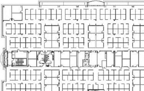
This section discusses both types using a typical office floor plan, as shown in Figure 8-1.
A coverage-oriented WLAN is designed to provide maximum WLAN coverage with the least amount of APs. (A typical coverage-oriented network provides a user to AP ratio of 25 to 1.) Some characteristics of a coverage-oriented deployment include the following:
Bursty, low packet rate application types, such as barcode scanning and database queries
Low bandwidth requirements, allowing data rate scaling down to lower data rates such as 1 or 2 Mbps
Ease of maintenance because of little or no support staff local to the WLAN
In coverage-oriented deployments, the typical applications have low packet rates and low bandwidth requirements. Because of these meager demands on the WLAN, the users can expect effective throughput in these deployments to be quite high.
This setup allows more users to leverage the WLAN while still maintaining adequate performance.
These types of deployments might be common in warehouse environments or retail environments where WLANs are mission critical for inventory control and just-in-time purchasing and where the IT staff is in a central site, with no local support staff to troubleshoot coverage issues.
Also, it might be common for small or medium branch offices to opt for such a deployment as an alternative to installing wired Ethernet. In these cases, the branch offices experience a significant amount of relocation and Category 5 cabling expenses are minimized. A simple-to-deploy WLAN provides basic network connectivity such as file and printer sharing.
Figure 8-2 illustrates the example floor plan from Figure 8-1 with a coverage-oriented WLAN deployment.
Figure 8-2 provides WLAN coverage with roughly 25 to 30 users per AP. To provide complete coverage for the floor, the plan uses 14 APs. Note that the deployment provides coverage to all areas, including storage closets, restrooms, and stairwells where coverage might not be normally required. It is reasonable to assume that other possible deployment configurations use fewer APs, but the configuration in Figure 8-2 is used for the sake of simplicity and illustration.
A capacity-oriented WLAN is designed to provide maximum throughput and packet rate for each client in a BSS. Capacity-oriented cell sizes are smaller than coverage-oriented cells, requiring a higher AP density. Capacity-oriented deployments are required for areas that have the following characteristics:
High packet rate applications
Latency-sensitive applications
Smaller-sized subnet deployments (or multiple subnets per coverage area)
Dense client population
Figure 8-3 illustrates the same floor plan with a capacity-oriented deployment. Note that there are more than twice as many APs in the capacity-oriented deployment (30 APs versus 14 APs).
The coverage area each AP provides is much smaller than in Figure 8-2; in fact, the cells are nearly half as small. Each AP provides coverage for roughly 12 users, and the entire deployment requires 30 APs as opposed to 14 APs in the coverage-oriented deployment.
A large number of deployments begin by providing coverage in common areas, such as conference rooms. The usual result from such a deployment is that users near the conference room leverage the WLAN while those who are farther away do without. These deployments are the seed to full-coverage deployments after the WLAN has been in place for some time. The user demand for WLANs usually forces the IT department to fully deploy at some point, so it might be useful to prepare for full deployments even when starting with a partial deployment.
It makes sense to perform an initial site survey for a complete coverage deployment. Figure 8-4 shows a partial deployment given the same coverage-oriented site survey from Figure 8-2. The deployed APs provide coverage to the common areas and conference rooms in the floor plan. The black dots represent the locations of APs for future deployment that will not interfere with the existing APs. Note that the deployed APs are in the same places as in Figure 8-2. This setup allows future deployments to occur without the need for additional costly site surveys.

Ultimately, what you as a system administrator or site surveyor need to know is the number, location, and configuration of APs in your facility. To understand how best to discover this information, as explained earlier, it is important to determine whether the end goal is a capacity-, coverage-, or hybrid-driven design that emphasizes both aspects. The physical aspect of performing a site survey gives an administrator insight into what coverage area each AP provides, the number of APs required to cover the given area, the channel and transmit power settings and style or gain of antennas required. With this information, an administrator can determine the user-to-AP ratio and estimate throughput and forwarding rate per user in a coverage-oriented deployment. For a capacity-oriented deployment, you might start from the desired throughput and forwarding rate per user and the user density to determine the user-to-AP ratio. In addition, you need to weigh other factors, such as the limitations of the wired infrastructure and its ability to service your APs. In the end, you will place and configure your APs to maximize the performance in the basic service area.
As the site survey engineer, you face many challenges, and you need to understand and evaluate them up front before you even start performing the physical site survey. For example, if you don't understand the wired infrastructure in a warehouse, you might find that you are placing APs in locations that exceed the 100 meter (m) Category 5 100BASE-T cable lengths. The result might be that you spend hours performing measurements, only to discover that you need to start over at the beginning. Many of the obstacles that you face can be specific to your industry, as in the previous warehousing example, where the vastness of the facility can require unique solutions. Although this section discusses the types of challenges you face and how to look for them, Chapter 10, “WLAN Design Considerations,” places those challenges into specific industries.
In addition to considering the size of the facility, you also need to be aware of how the wireless propagation environment can change over time. Working off the previous warehousing example, the environment provides different propagation characteristics with fully stocked shelves rather than empty shelves. You also need to pay attention to objects that tend to reflect microwave energy, causing multipath, as introduced in Chapter 7, “Radio Frequency Essentials,” or objects that absorb the radio waves, making propagation itself challenging. Shelves stocked with energy-absorbing paper products, for example, tend to limit the overall propagation of radio signals, while also providing obstructions that can create coverage shadows in much the same way that they can shadow light. In the opposite extreme, with fully exposed empty metal shelves, free propagation occurs along with potentially harmful multipath. Your survey needs to consider both extremes and the specific needs of the network under these conditions. To cover a deployment that will vary from empty shelves to fully stocked over time, you likely want to employ smaller or more directional coverage areas that put the RF energy right where it is needed from locations that will never be obstructed. At the same time, you want to minimize the amount of energy that bleeds into other areas when shelves are empty, either by lowering the transmit power settings or by utilizing directional antennas. In all cases, you need to take careful signal-strength measurements during the site survey to ensure a robust design.
In a retail environment, the demands on the network can change from light usage to heavy usage as store managers use a small number of 802.11 phones during business hours, and then large numbers of employees flood the wireless network during nightly inventory sessions using barcode scanners. These scanners might require the transmission of many small transaction packets that need to arrive at their destination within a certain amount of time. In contrast, a streaming video display of specials might just require very high through-put. In the former case, it is critical that you achieve 100 percent coverage wherever the scanners might be operating. Because there is little data to share, it is satisfactory to only provide lower data rate coverage in some areas. The video case will likely require high data rate coverage, but it will only be at a fixed location or at a subset of the locations where scanner coverage is required.
You might not be able to control some sources of interference, such as some cordless phones, microwave ovens, and even other WLAN networks. Non-802.11–based cordless phones represent the most common source of harmful interference to WLAN networks. These phones are often designed to operate in either of the 2.4 GHz or 5.8 GHz ISM bands, utilizing either frequency-hopping or direct-sequence technology. The degree of degradation, if any at all, depends upon the numbers and types of phones in use. Some consumer-grade 2.4 GHz phones might clutter the entire band, whereas others are more spectrum friendly. If only a single phone is in use, as in the home, the best guidance is to place the base station away from APs or locations where client activity is anticipated. An office environment with many phones might raise the overall noise floor, thereby inhibiting WLAN transmissions. The best guidance is to either use an 802.11-compliant phone system or keep your data and phone networks in different frequency bands.
The other interference concern, which often appears in healthcare applications, is mission-critical equipment to which your network could be a harmful source of interference. Because the 2.4 GHz ISM band was allocated for medical devices, some hospitals might have units operating in this band. In general, WLANs operate at much lower transmit power levels than medical devices, and you might be able to place them upon channels where medical devices are not located or at power levels where they will not interfere. First and foremost, you need to understand where your medical devices are located and what their characteristics are. WLAN equipment that is compliant with the requirements of the International Electrotechnical Commission (IEC) 601-1.2 meets the industry limits. This compliance does not ensure that interference will not occur, although it might reduce the chances. For complete assurance, if your facility does use mission-critical equipment in the 2.4 GHz band, you might find that the easiest design choice is to use 802.11a in a non-ISM band such as the U-NII-1 band.
The physical environment itself might provide other challenges if it requires your equipment to operate under extreme temperature, high or low humidity, or wet conditions. You might find that you need to provide coverage inside a refrigerated room in a warehouse, for example. In this case, it might be necessary to place the AP inside a heated enclosure if the required operating temperature falls outside the range specified by the manufacturer. Similarly, if you are creating outdoor hotspots and do not want to run a long RF cable from an indoor location for the AP to the outdoor antenna location, you might place the AP in a properly rated NEMA enclosure to protect it from the rain and elements.
If you need to provide coverage on multiple floors of a facility such as an apartment building, you also need to remember that your first-floor network might interfere with your second-floor network and vice versa, depending upon the design and construction of your building. This potential will lengthen the site survey process because it will be necessary not only to measure the signal strength on the desired floor, but also to measure it on the floor above and the floor below.
In retail or education environments, you might have special aesthetic requirements to hide the network infrastructure, either to protect it from vandalism or to meet specific corporate requirements. Under these circumstances, it is common to place plenum-rated APs above ceiling panels, if that space is available, and then place the antenna in the ceiling or wall itself. Because they are small and flat, patch antennas often work well in these circumstances.
In addition to these challenges, you need to consider the characteristics of the end-user clients. This consideration includes such factors as the types of client devices that your network will need to support, the nature of the workforce using the clients, and the type of applications they are running over the WLAN. With stationary PCs in an office environment, there will be very little roaming, so coverage can be more focused with less overlap. Even if laptops are in use, it might not be necessary to provide high data rate coverage away from desks and conference rooms. If your firm is an engineering firm that runs applications with high-bandwidth applications, such as CAD tools, you need to maximize capacity with much smaller cells and fewer users per cell. In contrast, if your end users are running session-based applications on barcode scanners, they might have minimal bandwidth requirements but require coverage that allows for seamless roaming with support for connectivity at all locations. With voice, your network will be filled with many small data packets, so you must understand the capacity of your WLAN infrastructure devices with respect to voice. In these examples, there can be no holes in your coverage. Some specialized client devices might not even support higher data rates. You must also take into account this possibility. From all these questions, your most basic need is to understand the throughput and packet-forwarding requirements on your network, on a global scale and in localized special requirements.
Wi-Fi CERTIFIED
The Wi-Fi CERTIFIED on your client devices ensures a base level of interoperability between devices from different vendors. It is imperative that both your access points and client devices have this logo. The Wi-Fi Alliance, as discussed in Chapter 7, “Radio Frequency Essentials,” performs interoperability testing so you can safely deploy without fear of interoperability concerns.
As indicated earlier, it is not enough to understand these wireless-driven requirements, but you must also have a thorough understanding of the LAN infrastructure to which you are interfacing. One of the most important questions is, “What is the topology of your network?” You need to understand the networking equipment, hubs, switches, and routers that you are connecting to and where it is located. You must also understand what types of media interfaces your LAN can provide. It is most likely unshielded twisted-pair (UTP), but it might also be fiber. Remember that 100BASE-T Ethernet can only run 100 m over Category 5 UTP. If Dynamic Host Configuration Protocol (DHCP) is in use, where is the server and what lease times are in use? A WLAN network of clients might have very different LAN client network requirements.
You need to know whether cabling is routed through plenum spaces and whether your infrastructure equipment needs to be capable of being deployed there. Most buildings have firewalls, and the National Electric Code specifies procedures for penetrating them. You should measure cable lengths with straight segments and 90 degree turns; provide for service loops for the cabling contractor to deal with unforeseen issues; and, if antenna cables are in use, minimize their length and be aware of the losses they introduce at your operating frequency.
With your WLAN challenges, requirements, and goals, it is time to gather the tools you need to conduct your site survey:
The client device, radio, and antenna that you expect to service with your network.
APs with battery packs to run the APs for at least 8 hours.
Two of each type of antenna you anticipate using.
Mounting tools for the AP, battery pack, and antenna. They can include brackets, duct tape, and zip ties.
Markers to indicate the locations of APs.
Measuring wheel for horizontal and vertical distances.
RF cable or attenuator, if you anticipate using remote antennas.
A SW tool that provides the receive signal level, signal quality, noise and interference level, and packet transfer performance.
After you gather all the necessary tools, it is time to conduct the survey. Remember, as indicated at the beginning of this section, the questions you need to answer during your site survey are
Where are the APs located?
How are they mounted?
How do they connect to the LAN?
Where do you need to install cables and power?
What antennas are used, and where are they located and mounted?
How should you set configuration parameters that result in coverage factors such as power and data rate?
What channel settings should be used?
The answers should be detailed enough that someone else could perform the install.
Considering the two extremes of a coverage-oriented approach and a capacity-oriented approach, your physical survey follows slightly different steps. With both, you should set channel assignments to avoid overlap and do each survey on the channel that will be used. You should also survey at the minimum desired data rate. In the multifloor case, remember that the floors above and below are part of the extremities, and you need to make measurements there as well. Do all measurements on the channel you intend to use—or you might get bitten by unknown interference. If cells seem smaller than expected, try changing channels because there might be interference issues.
With the coverage-oriented approach, choose one of the edges of your desired coverage area and place an AP there. Now, walk toward the center of the desired coverage area, until you locate the boundary of desired coverage. Move the AP to that location and survey the coverage. At this point, you have two options:
Take the same approach with the other extremities and then fill in the holes in the middle.
Place the next AP at the edge of the current one, find its coverage edge, and move the AP to that location. Work your way around the facility in a similar fashion.
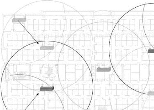
With either of these approaches, you need to define your edges to allow for the appropriate level of overlap. Figure 8-5 shows an example of the extremity approach, and Figure 8-6 shows the AP-to-AP approach. In each figure, the channel in use is indicated in the center of each range circle. The lighter-shade APs indicate the initial locations used to determine the center point for the AP. The arrows show how the positioning of one AP determines the next AP's location.

With a capacity-oriented approach, determine the number of users you want to attach to each AP and the user density, and from that, determine the desired cell radius. Use the same techniques as before, but adjust the power until you achieve the desired size cell. You should most likely use the extremity approach when you have isolated pockets of users, but you might use the other approach when the user density is fixed throughout the environment.
Depending upon the complexity of the site and the requirements, you might experience a lot of trial and error. You need to be creative at times because there might be many solutions to the puzzle.
After you finish a site survey and physical deployment mapping, the second phase of WLAN deployment can begin. A secure WLAN requires an authentication, authorization, and accounting (AAA) server such as RADIUS to allow for user-based authentication. In addition, you should also deploy a mechanism to manage the WLAN, either by extending an existing management platform, such as CiscoWorks, or by introducing a domain-specific platform just to manage the WLAN.
Chapter 4, “802.11 Wireless LAN Security,” covers security in depth and delves into how 802.1x is ingrained in the WiFi Protected Access (WPA) specification and the forthcoming 802.11i standard for WLAN security. The solution requires a AAA server to provide user-based authentication. The AAA server is probably located in a secured data center, several router hops away for the network edge. With the advent of Layer 3, wire rate switching, you can measure the network latency between the network edge and the data center in single digit milliseconds, if not microseconds.
802.1x-based deployments become more complicated when distributed across a WAN link. WAN links are generally lower bandwidth than LAN connections, and as a result, congestion can occur on these links. Congestion can have a significant impact on 802.1x-based authentication in that dropped RADIUS packets can cause client-station authentications to time out and fail, as well as potentially impact roaming, as depicted in Figure 8-7.

You can alleviate the problem in a couple of ways:
Use QoS to prioritize 802.1x RADIUS packets across the WAN.
Install a local AAA server at the remote site.
Using QoS to prioritize RADIUS packets is easy. It provides priority for 802.1x packets during WAN congestion. For those who already have QoS deployed to support VoIP applications, the process to augment Cisco router and switch configurations in nominal.
VoIP typically has an IP precedence value of 5 and a differentiated services code point (DSCP) value of expedited forwarding (EF). Video usually has an IP precedence of value of 4 and DSCP value of AF41 through AF43. VoIP call control (MGCP or H.323) usually has an IP precedence value of 3 and DSCP value of AF31 to AF33. 802.1X RADIUS packets can be viewed as control traffic that is network critical, so it is reasonable to classify it along with VoIP call control with an IP precedence of 3 or DSCP of AF31 to AF33. These values are summarized in Table 8-1.
Table 8-1. IP QoS Summary
Function | IP Precedence Value | DSCP Value |
|---|---|---|
Voice (VoIP) | 5 | EF |
Video | 4 | AF41–AF43 |
Signaling (VoIP call control, 802.1x) | 3 | AF31–AF33 |
Normal data | 0 | 0 |
Using QoS to prioritize 802.1x RADIUS traffic does not solve every issue associated with remote site authentication. The following issues persist:
WAN outage
WAN latency
If the WAN link were to become unavailable, the client station would be unable to access the WLAN, barring the user from accessing local resources. WAN links with very high latency (such as VSAT) can also negatively impact authentication because the AP or client might simply time out the authentication attempt. This scenario leads to poor station performance.
Local authentication at remote sites might seem like the obvious answer to the problem, but by no means is it a panacea. Deploying AAA servers at remote sites has issues:
Expense—. Large remote-site deployments require at least one server per site.
Manageability
Authentication servers could number into the thousands, depending on the deployment.
The replication of user databases to large numbers of remote sites can be problematic.
Administrator access can be an issue if remote-site administrators need to constantly access the central server.
Some vendors, such as Cisco Systems, incorporate WAN survivability into their APs to let customers avoid the expense and to manage the headaches associated with local AAA servers, as shown in Figure 8-8.

Although the solution is not perfect, it enables administrators to confidently deploy WLANs in remote sites while maintaining a single authentication database to manage.
Network management, and in particular WLAN management, is a topic that requires a book unto itself. This section highlights some key concepts to consider during deployment.
In any type of network,
You cannot manage what you cannot measure.
Many large networks can have as many as a thousand managed devices. In a typical large enterprise WLAN deployment, it is not uncommon to see nearly three times that many APs. WLANs can have a major impact on how you manage your network and also challenge the existing tools you use. To have a WLAN that performs as reliably as a wired LAN and minimize the management complexity, you need a management solution that includes WLAN management.
Many early adopters of WLANs have been plagued by the management burden of WLANs. Most cost-effective management packages hardly scale to several thousand devices without requiring multiple management stations, and none offer RF-specific management functionality. This absence left these deployments with poor-performing WLAN deployments and forced administrators to develop their own toolkits for effectively managing WLANs. Today, however, most laptops ship with 802.11 network interface cards (NICs) as standard equipment, and users are starting to rely on WLANs and demand the same level of availability as wired networks.
Many WLAN management solutions provide wired-like management services: Simple Network Management Protocol (SNMP) polling, fault monitoring, trap collection, configuration distribution, firmware distribution, and so on. No available solutions give the administrator insight into the radio network itself. WLAN performance varies widely with each implementation. Materials in the walls and the location of external interferers such as microwave ovens can impact the performance of WLANs, and the introduction of Bluetooth devices, ad-hoc clients, and neighbors using WLANs can degrade the performance of a WLAN to the point of making it useless.
Radio management gives the administrator clear visibility into all these issues and, depending on the solution implementation, can automate the control of radio parameters such as frequency/channel selection and client/AP transmit power to adapt to harsh RF environments.
Seek solutions that provide this functionality because it will make your job as an administrator much easier. RF networking is such a drastic departure from wired networking that without years of experience, finding a management tool that performs complex site survey calculations, path loss, interference detection, and possible location services certainly makes sense.
The decisions you make when deploying a WLAN are crucial to optimal WLAN performance:
What kinds of users will use the WLAN (highly mobile versus nomadic)?
What kinds of applications will these users use on the WLAN?
Although these two questions are basic and almost self-explanatory, they are typically overlooked at deployment time. They are the foundation for saving costs during the life of the deployment, namely in selecting a deployment scenario, whether it is coverage oriented or capacity oriented.
Once you understand how you want to deploy, knowing what tools to use to perform site surveys and the best practices for a site survey can save you time and money for a tedious and time-consuming task. Today, site surveying is a manual task, meaning that the person doing the survey performs all the measurements and calculations. With the growth of WLANs and management tools that automate some of these processes, it is reasonable to expect the same performance and reliability from a WLAN as you do from a wired network.