
Chapter 12
Shapes and Boundaries
12.1 Introduction
In this chapter we shall investigate tools for examining image shapes. Some tools have
already been discussed in Chapter 10; now we look at specific methods for examining shapes
of objects. Questions we might ask about shapes include:
• How do we tell if two objects have the same shape?
• How can we classify shape?
• How can we describe the shape of an object?
Formal means of describing shapes are called shape descriptors. Shape descriptors may
include size, symmetry, and length of perimeter. A precise definition of the exact shape in
some efficient manner is a shape representation.
In this chapter we shall be concerned with the boundary of objects. A boundary differs
from an edge in that whereas an edge is an example of a local prop erty of an image, a
boundary is a global property.
12.2 Chain Codes and Shape Numbers
The idea of a chain code is quite straightforward; we walk around the boundary of an
object, taking note of the directions we take. The resulting list of direction is the chain
code.
We need to consider two types of boundaries: 4-connected and 8-connected (see Chap-
ter 11. If the boundary is 4-connected, there are four possible directions in which to walk;
if the boundary is 8-connected, there are eight possible directions. These are shown in
Figure 12.1.
To see how they work, consider the object and its boundary shown in Figure 12.2.
Suppose we walk along the boundary in a clockwise direction starting at the left-most
point in the bottom row, and list the directions as we go. This is shown in Figure 12.3.
We can thus read off the chain code as:
3 3 3 2 3 3 0 0 0 1 0 1 1 1 2 1 2 2
If we treat the obj ect in Figure 12.2 as being 8-connected, then its boundary and chain
code are generated as in the right-hand diagram in Figure 12.3. In this case, the resulting
chain code is:
6 6 5 6 6 0 0 0 1 5 5 5 3 4 4
351

352 A Computational Introduction to Digital Image Processing, Second Edition
0
1
2
3
Directions f or 4-connectedness
0
1
2
3
4
5
6
7
Directions f or 8-connectedness
FIGURE 12.1: Directions for chain codes
0 1 1 1 0
0 1 1 1 1
0 1 1 1 1
1 1 1 1 1
1 1 1 1 1
1 1 1 1 0
FIGURE 12.2: A 4-connected object and its boundary
0 0 0
1
0
1
1
1
2
1
22
3
3
3
2
3
3
Start
0 0 0
1
2
2
2
3
44
6
6
5
6
6
Start
FIGURE 12.3: Obtaining the chain code f rom the object in Figure 12.2

Shapes and Boundaries 353
To obtain the chain code in MATLAB, we have to write a small f unction to do the job for
us. We have to first be able to trace out the boundary of our object, and once we can do
that, we can write down our directions to form the chain code. A simple boundary following
algorithm has been given by Sonka et al. [49]. For simplicity, we shall j ust give the version
for 4-connected boundaries:
1. Start by finding the pixel in the object that has the left-most value in the topmost
row; call this pixel P
0
. Define a variable dir (for direction), and set it equal to 3.
(Since P
0
is the top left pixel in the object, the direction to the next pixel must be 3.)
2. Traverse the 3 × 3 neighborhood of the current pixel in an anticlockwise direction,
beginning the search at the pixel in direction
dir + 3 (mod 4)
This simp ly sets the current direction to the first direction anticlockwise from
dir:
dir 0 1 2 3
dir + 3 (mod 4) 3 0 1 2
The first foreground pixel will be the new boundary element. Update dir.
3. Stop when the current boundary element P
n
is equal to the second element P
1
and
the previous boundary pixel P
n−1
is equal to the first boundary element P
0
.
Suppose we have a binary image im consisting of a single object. We can find the top left
pixel with the following MATLAB commands:
MATLAB/Octave
>> [x,y] = find(im==1);
>> x = min(x)
>> imx = im(x,:);
>> imy = min(imx)
or in Python with
Python
In : x,y = np.where(im==1)
In : mx = mx.min()
In : my = y[np.where(x==mx)].min()
pixels. The second command finds the minimum of the first coordinates. Thus, mx is the
top row of the object. The third command isolates this top row, and the final command
finds the left-most column in it.
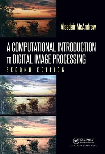
Given the indices
x and y of the current pixel, and the value dir, how do we implement
Step 2? We give a simple example, shown in Figure 12.4. Suppose that in this particular
example, the current value of
dir is 0 so that
dir + 3 (mod 4) = 3.
The dotted arrows indicate the direction of traversing (starting from the pixel in direction
3 from P
k
) until we reach a new foreground pixel. This pixel is then P
k+1
.
354 A Computational Introduction to Digital Image Processing, Second Edition
0 0 0
0
0
1 1
1 1
0
3
P
k+1
P
k
FIGURE 12.4: Traversing a neighborhood
We start by noting the row and column increments to the four-neighbors of a pixel:
−1 0
0 −1 0 0 0 1
1 0
Since we are looking at four-connected boundaries, these are the only neighbors we need.
We can put these into a matrix, with the first row corresp onding to the increments in
direction 0:
n =
0 1
−1 0
0 −1
1 0
This means that the indices in the j-th row correspond to the increments in indices in
direction j − 1. Thus, given a direction dir, we can enter:
MATLAB/Octave
>> newdir = mod(dir+3,4);
>> for i=0:3,
> j=mod(newdir+i,4)+1;
> tt(i+1) = im(x+n(j,1),y+n(j,2)),
> end
or
Python
In : newdir = mod(dir+3,4)
In : for i in range(4):
...: j = mod(newdir+i,4)
...: tt[i] = im[x+n[j,0],y+n[j,1]]
and this will traverse the neighborhood of our image im at position (x, y) starting from the
correct direction. Notice that for MATLAB and Octave we need to set

Shapes and Boundaries 355
MATLAB/Octave
>> j = mod(newdir+i,4)+1;
The extra “
+1
” takes account of the fact that the modulus function returns values 0, 1, 2, 3,
but the rows of
n
are 1, 2, 3, 4. The vector
tt
contains the values of the neighborhood as it
is traversed.
The first non-zero value is easily found with
MATLAB/Octave
>> d = min(find(tt==1));
or with
Python
In : d = min(flatnonzero(tt==uint8(1)))
and now we can update dir, and the position of the current pixel:
MATLAB/Octave
>> dir = mod(newdir+d-1,4);
>> x = x+n(dir+1,1);
>> y = y+n(dir+1,2);
or
Python
In : dir = mod(newdir+d,4)
In : x = x+n[dir,0]
In : y = y+n[dir,1]
This most recent value of dir is placed into a vector, and this is the vector which will be
the final chain code.
Functions for implementing the full chaincode are given at the end of the chapter.
These programs can be tested with the shape in Figure 12.2 (surrounding the image
with zeros first):
MATLAB/Octave
>> test = zeros(8,7); test(2:7,3:5) = 1; test(5:7,2) = 1; test(3:6,6) = 1;
>> [cc,bdy] = shape(test,4);
>> uint8(cc)
ans =
3 3 3 2 3 3 0 0 0 1 0 1 1 1 2 1 2 2
and comparing this with the code given earlier, the function has indeed returned the correct
chain code.
We can easily modify the program to perform chain codes for 8-connected boundaries.
The above algorithm must be slightly changed; again, see Sonka et al. [49].
1. Start by finding the pixel in the object that has the left most value in the topmost
row; call this pixel P
0
. Define a variable dir (for direction), and set it equal to 7.
(Since P
0
is the top left pixel in the object, the direction to the next pixel must be 7.)
..................Content has been hidden....................
You can't read the all page of ebook, please click here login for view all page.