
10 Machine consoles

Figure 10.1: Maintenance control console room of an AN/FSQ-7 installation (courtesy Air Force History Support Office)
A giant duplex computer installation like an AN/FSQ-7 or -8 requires equally giant maintenance operation consoles to monitor the computers and their associated input /output equipment. These consoles were icons not only of their time but are still used today in a variety of movies whenever the impression of a giant computer is required. So even if there is no longer any AN/FSQ-7 still operating, at least parts of its maintenance consoles are still used to represent the archetypal electron brain.
Figure 10.1 shows a view of the maintenance control console room of an AN/FSQ-7 installation looking from the simplex maintenance console (not visible here) across the room. On the left and right are the two duplex maintenance consoles, one for each of the two computers. In the center is the IBM 718 line printer while the duplex switching console can be seen in the middle of the far end of the room.
An early rendition of a duplex maintenance console is shown in figure 10.2. It contains a plethora of neon indicators giving an insight into the current operation of one of the two duplexed computers and its attached input/output systems. It was quite common to place a Polaroid camera mounted on a tripod in front of this console when a computer had crashed to take a snapshot of the register contents as displayed by the hundreds and hundreds of neon lights. These pictures could later be analyzed to determine the cause of the crash. In addition to this, the duplex consoles featured a speaker with an associated audio amplifier as shown in figure 10.3: By means of a selector switch, this amplifier could be connected to one of the two leftmost bits of the left or right arithmetic unit of the computer. An experienced operator could recognize the patterns of humming noises emanating from the speaker. Using this feature, endless loops, sudden changes in the operation of the computer etc. could be spotted in an instant.

Figure 10.2: Duplex maintenance console with display controls (see [IBM DSP 1][p. 3])

Figure 10.3: Console audio amplifier (see [IBM CCS XD][p. 412])
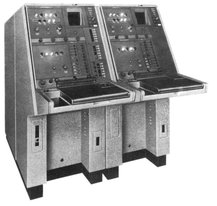
Figure 10.4: Duplex switching console (see [IBM CCS I][p. 23]
Typically, one of the duplexed computers was the active computer while the second system was in standby mode. Under normal conditions, this second computer monitored the active computer and periodically copied live data from this to minimize switchover time in case of an emergency like a crash or hardware fault on the active side.448 Under these ideal circumstances, a switchover was only a matter of seconds and was performed using the duplex switching console shown in figure 10.4. A scheduled switchover, which occurred on a daily basis, transferred approximately half of the core memory’s contents from the active to the standby computer as well as most of the current data on the LOG, MIXD, RD, and TD drums.449

Figure 10.5: Simplex maintenance console (see [IBM DSP 1][p. 9])
Not visible in figure 10.1 is the so-called simplex maintenance console which is located on the front side of the maintenance console room from where this picture was taken. This console is shown in detail in figure 10.5. It contains all control and display elements for simplex equipment in an AN/FSQ-7/8 installation.450 From left to right, these are an optional blank panel for later addition of a maintenance oscilloscope and probe facilities, an intercommunication telephone, the marginal checking panel and the many control panels for GFI, Computer Entry Punch (CEP), LRI, XTL, and TPG.451