
11 Power supply
Powering a DC with its duplex AN/FSQ-7, the complex input/output equipment, and its more than 100 display consoles is a formidable task.452 Such an installation required roughly 3,000 kW of which 1,000 kW were used for the duplex computer system with all of its associated equipment while the remaining 2,000 kW were required for lighting and the air conditioning system. Since power outages often had devastating effects on the vacuum tubes in the computer and its associated equipment,453 utmost stability and availability of the power supply equipment were of prime importance.
11.1 The powerhouse
Each DC and CC featured a dedicated powerhouse which can be seen in figure 4.5 in section 4.3 as the flat building directly next to the four story DC blockhouse. This building housed five diesel engines with attached generators, each capable of delivering 650 kW as 480 V AC power. Figure 11.1 shows one of these diesel generator units installed at DC-03 at Syracuse in 1956.
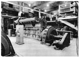
Figure 11. 1: Diesel engines and generators at DC-03, Syracuse, September 1956 (courtesy of Air Force Historical Research Agency)
The powerhouse also contained two so-called load centers, each featuring a 300 kVA transformer yielding 120 V and 208 V from the 480 V supply and associated circuit breakers, and three substations containing one 500 kVA transformer each. Only two substations were actually necessary for operation of the DC or CC, the third could replace a failed substation or load center in case of an emergency.454
Figure 11.2 gives an impression of the overall power distribution system. On top are the diesel generators with the associated load centers and substations while the equipment shown in the lower half was located in the DC building itself. Although the powerhouse had its own maintenance and operations staff, they were closely knit with their counterparts in the blockhouse operating and maintaining the computer and air conditioning.
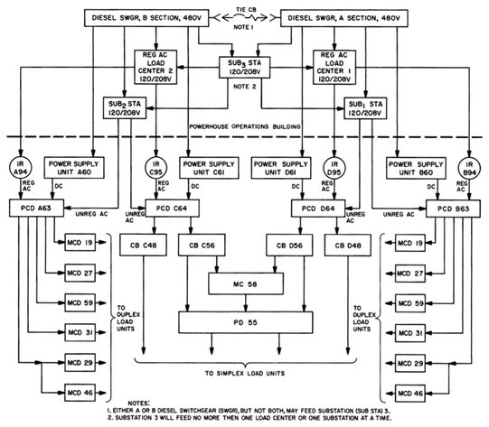
Figure 11.2: Load centers and substations (see [IBM POWER][p. 4])
11.2 Regulated power supplies
The raw output voltages generated by diesel driven generators are, of course, not suitable for running an intricate and fragile digital computer like the AN/FSQ-7/8. This task required a wide variety of regulated AC and DC voltages at high currents.
AC regulation was done by induction regulators fed by the 480 V output from the powerhouse. These regulators were basically motor-driven variable induction transformers.455 These AC regulators typically delivered three phase power at 120 V and 208 V to loads such as the filament transformers in the computer.
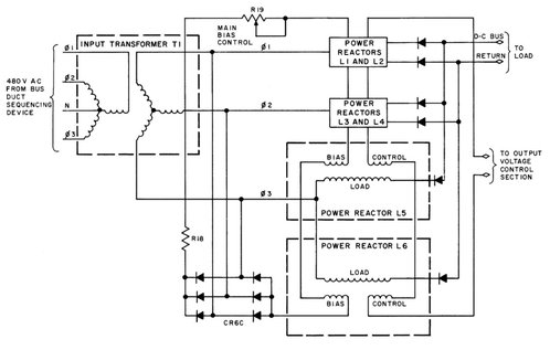
Figure 11.3: Principle of operation of a typical DC power supply (see [IBM POWER][p. 31])
More interesting are the regulated DC power supplies: To generate the multitude of different stabilized DC voltages required by the duplexed computers and their simplex equipment, the 480 V AC output delivered by the powerhouse was transformed to a voltage near the desired DC level in a first step, by means of a suitable step-down transformer as shown on the left of figure 11.3. The secondary of this transformer then fed a number of power reactors. These are essentially saturable reactors, i. e. transformers with additional control windings allowing to change the saturation of the iron core. The power reactors shown in figure 11.3 feature two such control windings, one bias winding and one control winding. Coarse setting of the DC output voltage was done by adjusting the bias current while a regulation circuit generated the necessary current to drive the control windings.
The control circuit driving the inputs denoted “to output voltage control section” was based on a magnetic amplifier – basically just another saturable reactor. The saturation control winding of this amplifier was driven by a current derived from the voltage difference between the power supply’s DC output and a reference voltage derived from a ZENER diode456 circuit. Small changes in this difference had large effects on the inductive resistance of this magnetic amplifier and caused a corrective current driving the control windings of the power reactors.457 Table 11.1 shows the various stabilized DC voltages required for an AN/FSQ-7 installation with typical current ratings.
| Rated current (A) | Rated current (A) | ||||
|---|---|---|---|---|---|
| Voltage | Simplex | Duplex | Voltage | Simplex | Duplex |
| +600 | 85 | 3 | −30 | 70 | 120 |
| +250 | 50 | 65 | −150 | 80 | 225 |
| +150 | 75 | 120 | −300 | 30 | 55 |
| +90 | 60 | 130 | −48 | 560 | 450 |
| +10 | 100 | 45 | −72 | 13 | |
| −15 | 10 | 20 | |||
Table 11.1: Current ratings (see [IBM POWER][p. 30])
Unregulated AC from the two operational substations, regulated AC from the load centers and induction regulators, and regulated DC were fed to four power control and distribution units, PCD for short, in each installation. Two of these units fed the duplexed computers while two supplied the simplex equipment. Fed by the PCDs are the marginal checking and distribution units, MCD for short which in turn fed the computer, input/output, and display equipment.
11.3 Power distribution
Figure 11.4 shows the overall schematic of the power distribution system of an AN/FSQ-7 installation: The four PCD units are shown at the top. The duplex equipment (the central computers, display systems, manual input system, warning light system, drums, output system etc.) were powered by twelve MCD units described in the following section.
The official procedure of applying power to a duplex computer system gives an impression of the complexity of the task as well as of the fragility of the vacuum tube equipment:458
“The following procedures are to be used as general guidelines to recycle duplex power to a computer:
- After a power failure or a scheduled power outage, open the AC input switches to both main and auxiliary drums.
- Obtain approval from power plant personnel to recycle power. Depress the AC Only push button firmly. If power fails to recycle properly, inform the power plant personnel and check our system for failure indications. Do not attempt to recycle power until the OK is received from power plant.
- Allow a maximum of 10 minutes to warm up the filaments prior to applying DC to the loads.
- Request unregulated AC be reapplied if required.
- Check and insure filament voltages are set to 120 volts AC.

Figure 11.4: Block diagram of the power distribution system for an AN/FSQ-7 (see [IBM POWER][p. 46])
- After the filament warmup has elapsed, depress the power on push button. There is no requirement to notify the power plant prior to this action. All units may have DC applied at the same time via the Power On push button.
- Apply power to the drum motors. Do not attempt to cycle main and auxiliary drums at the same time.
- Repair any obvious failures, then begin the computer checkout with ADIOS-AUOC. Once a failure is detected, run any program that may help solving the problem. AUOC will give an overall analysis; therefore, possibly enabling two problems to be worked on simultaneously. Marginal check program passes are desirable if they can be accomplished during the troubleshooting and repairing of other areas of the computer.
- Closeout the ESR after AUOC has cycled error-free for 10-15 minutes.”
11.4 Marginal checking system
Marginal checking was pioneered in Whirlwind and proved necessary to achieve the required margins of reliability of the computer systems used in the air defense system:
“Marginal checking is a preventive maintenance procedure used to increase the reliability of AN/FSQ-7 and -8 equipment. A computer containing 5,000 tubes and 10,000 diodes can be expected to fail every half hour after the circuit elements are initially aged. Since the number of diodes and tubes in AN/FSQ-7 and -8 equipment exceeds these quantities, computer failure can be expected more frequently than every half hour. The Marginal Checking System is incorporated to increase the useful operating time of the equipment by determining the components which are likely to fail between scheduled maintenance periods. In addition to determining the reliability of the equipment, the Marginal Checking System also aids maintenance personnel in diagnosing and locating troubles.”459
Basically, marginal checking may vary filament voltages and stabilized DC voltages of a system. Filament marginal checking was only used in some display consoles, an application where reduced emissions result in a dimmer picture. The duplex computer systems with all of their associated equipment were subjected only to variations of their most critical DC supply voltages.
Figure 11.5 shows a typical equipment life curve: The x-axis denotes time of operation of equipment while the y-axis shows the allowable margin460 of variation concerning a vital parameter such as supply voltage. The voltage at which a particular circuit still operates reliably is determined by deliberately varying its supply voltages. Based on this voltage, the operational margin of the equipment under test is determined.
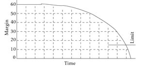
Figure 11.5: Typical life curve
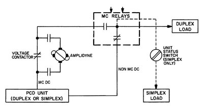
Figure 11.6: Principle of operation of marginal checking (see [IBM MC] [p. 13])
This margin is then compared to a predefined limit – if it is less than this limit, the circuit will be replaced instead of waiting for it to fail due to aging processes. Such life curves were determined for all of the equipment being subject to marginal checking. To simplify fault isolation, marginal checking was applied to subsystems as small as possible at once.
The +250 V, +150 V, +90 V, −150 V, and −300 V supply lines could be varied by means of a so-called amplidyne. An amplidyne is basically a motor-generator unit with an externally driven field-control winding on the generator side. Changing the current flowing through this winding changes the output voltage of the generator. Each of the twelve marginal checking systems contained one amplidyne, so only one of the aforementioned voltages could be varied in an equipment group at a time. These am-plidynes consisted of a 3 kW 125 V DC generator and a 208 V, 3-phase, 5 hp motor running at 1,800 rpm. The gain of such an amplidyne configuration is remarkable –typical values are in the range of 10,000 to 50,000, so small changes in the field-control winding result in rather large changes at the generator’s output. As shown in figure 11.6, the amplidyne was switched in series to the voltage under excursion during a marginal check operation.
Marginal checking was performed only on equipment in the standby state as determined by switches at the respective control consoles. The MC system allowed three modes of operation: Calculator mode in which the MC system was under program control, 461 manual mode, which was controlled from the MC control panel located in the maintenance console room and was normally used to perform a drill-down analysis to isolate units at fault which could not be identified during a calculator mode run, and, finally, satellite mode. This mode was similar to manual mode with the exception that a portable potentiometer was used to control the voltage excursions. This mode allowed marginal checking under manual control while servicing the computer system.462

Figure 11.7: MC control panel, duplex maintenance console (see [IBM MC][p. 44])
Figure 11.7 shows the MC control panel located on the duplex maintenance console. The switches on the left select the unit (memory, arithmetic etc.), the circuit, supply line, and voltage to be varied.463 The right hand side contains a voltmeter indicating the amplidyne output voltage and controls for manual excursions.