
12 Programming
Programming an early computer like the AN/FSQ-7 was quite different from today’s perspective as many of the modern programming idioms, such as using a stack for parameter passing to subroutines and storing return addresses etc. were not used back then. In addition to that, the two 16 bit arithmetic elements of the AN/FSQ-7, working in parallel, are still a rather unusual feature.
The following sections give an overview of the instruction format, instruction set, and typical programming idioms with regard to indexing and subroutine handling. The final AN/FSQ-7/8 computers featured 59 different instructions grouped into eight classes, while the XD-1 prototype implemented only 48 instructions. All following examples and tables are based on this original set of instructions.
12.1 Instruction format
The instruction set of AN/FSQ-7/8 looks quite RISC464-like from a modern point of view: Each instruction occupies one machine word of 32 bits (plus one parity bit) and there are no provisions for intricate operand address manipulations apart from a simple index adder. Nevertheless, the instruction format shown in figure 12.1 looks a bit cluttered at first sight.
The right half-word of each instruction contains its (in many cases optional) operand address while the left half-word specifies the instruction to be executed. This straightforward addressing scheme was sufficient for the early incarnation of AN/FSQ-7 with its two core memory systems of only 4 k words each. With the replacement of one of these memories by a 64 k system, a total of 68 k words of main memory (plus 32 addresses for the test memory) became available, rendering the 16 bits of the right half-word insufficient to store an address. Therefore the sign bit of the left half-word –prior to this unused in the instructions – was logically assigned to the address portion of an instruction, thus allowing a 17 bit address space, more than sufficient for the 4 k plus 64 k complement of main memory. When addressing memory, the sign bits lose their special meaning since addresses are always unsigned quantities.
The first three bits of an instruction specify which – if any – of the available five index registers is to be used for generating an operand address.465 If no indexed addressing is to be used, these bits contain 000. The next three bits select the instruction class. The remaining bits specify the variation of the instruction and a lot of other details depending on the instruction class and variation.
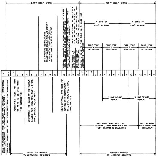
Figure 12.1: Structure of AN/FSQ-7 instructions (see [IBM CCS I][p. 94])
12.2 Instruction set
Table 12.1 shows all 48 instructions present in the XD-1 and XD-2 systems in 1955, being clustered into eight instruction groups, each containing up to sixteen instructions. These instructions will be described in more detail in the following subsections466 using a C-like notation to describe the operation of the instructions. So mem[address + index] denotes the contents of the memory location addressed by an operand address plus the contents of an index register etc. The abbreviation AC for the accumulator always denotes the left and right accumulator of the two arithmetic elements. The same holds true for the A and B registers. “: =” denotes the assignment operation.
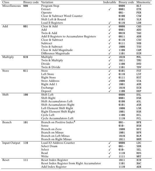
Table 12.1: XD-1/XD-2 instruction set in 1955 (see [IBM CCS XD][p. 65]467
12.2.1 Miscellaneous class
This group contains instructions which, as the name implies, do not fit readily into other classes, including the PER instruction implemented by the selection element.468
HLT: This instruction halts operation of the central computer. If an input/output operation is still pending as denoted by the IO interlock, the instruction is delayed until completion of this operation.
ETR: The extract instruction is, in fact, a bitwise AND operation and implements AC := AC & mem[address + index]. The operand’s address is contained in the right half-word of the instruction and can be indexed. Since not only the instruction word, but an operand value must be fetched from main memory, the overall execution time for this instruction is 12µs.
PER: Using the operate instruction, input/output devices469 can be controlled. Execution time is 12µs.
CSW: The clear and subtract word counter instruction transfers the contents of the input /output word counter to the right accumulator in 6µs.
SLR: Shift left and round shifts the left and right accumulator and B register simultaneously n places to the left. Each accumulator/B register pair is treated as a single 32 bit shift register. Bits shifted out to the left from bit 1 of the accumulators are discarded while the respective accumulator sign bit (which is not changed by this instruction) is used to fill the B register from the right.
Both accumulators will be rounded off to 15 significant bits by this instruction: A 1 is added to a positive value in the respective AC if the sign bit of its corresponding BR is set to 1. In case of a negative number in the AC, a 1 is subtracted if the BR sign is 1.
The A and B registers of both arithmetic units are set to a positive zero, i. e. 00...0, after completion of this instruction which takes a variable time to complete, depending on n.
LDB: The Load B register instruction loads the B register with the operand fetched from the specified memory address (indexable): BR := mem[address + index]
Illegal instructions: All other instruction variations of the miscellaneous class have no effect other than requiring 6µs before the next instruction is executed.
12.2.2 Add class
CAD: The clear and add instruction effectively loads the accumulator with the operand specified, requiring 12µs: AC := mem[address + index]
ADD: This instruction adds the left and right halves of the operand fetched from memory to the left and right accumulators. The A registers are set to +0, execution time is 12µs, and an overflow may result from this instruction.
TAD: The difference between ADD and the twin and add instruction is that the latter adds the contents of the left half-word read from memory to the left and right accumulator. The A registers are reset to +0, and an overflow may occur.
ADB: The add B registers to accumulators instruction requires 12µs to complete. The A registers are reset to +0, and an overflow condition may result.
CSU: Clear and subtract works similarly to CAD but the accumulators are loaded with the complement of the operand specified:470 AC := !mem[address + index]. The execution time is 12µs.
SUB: This instruction subtracts the left and right half-words of the operand specified from the left and right accumulators. An overflow may occur, execution time is 12µs, and the A registers are set to +0.
TSU: Similarly to TAD, the twin and subtract instruction subtracts the left half-word of its operand from both accumulators in parallel, requiring 12µs to complete. The A registers are set to +0, and an overflow may occur.
CAM: The clear and add magnitudes instruction loads both accumulators with the positive left and right magnitudes of its operand. The A registers are set to +0; execution time is 12µs.
DIM: Difference magnitudes subtracts the positive magnitudes of the left and right half-words of the operand from the accumulators, leaving the A registers set to +0, while the B registers contain the original contents of the accumulators. This instruction requires 12µs to complete.
Illegal instructions: All other add class variations are illegal instructions. Their execution adds the contents of the left half-word of the memory location specified by the operand address plus index register contents to be added to the left accumulator which may cause an overflow. The AR is set to +0.
12.2.3 Multiply class
MUL: The multiply instruction multiplies the contents of the left and right accumulators with the corresponding left and right half-words of the operand fetched from mem[address + index]. The magnitudes of the two operand halves are placed in the A registers, both B register bits at position 15 will contain a copy of the sign bit of their associated accumulator. Thanks to the implicit shift operation performed by the arithmetic elements, execution time for a multiplication is only 17 ± 0.5µs.
TMU: Twin and multiply works similar to the MUL instruction with the exception that both accumulators are multiplied with the same value, namely the left half-word of the operand fetched from memory.
DVD: The divide instruction divides contents of the left and right accumulators by the left and right half-words of mem [address + index]. After completion of this instruction, which requires 51µs or 52µs, the magnitudes of the quotients are left in the B registers, while the remainders of the two divisions are stored in the respective accumulators. Remainders and corresponding quotients have equal signs.
One quirk should be noted: If bit 15 of the right B register is set to 1 after the division, the complement of the right half-word of the operand remains in the A register which will contain the uncomplemented right half-word of the operand otherwise.
TDV: Twin and divide works quite like DVD but both accumulator contents are divided by the left half-word of the operand.
Illegal instructions: The illegal instructions of this class, each requiring 12µs to complete, are the most complex ones in the computer system: If the left sign bit of the operand mem[address + index] is set and if bits 10 to 15 of the right half-word of the instruction word contain 000000 or 000001, then the left accumulator and left B register will be complemented.
If the operand’s left sign bit is not set, the computer will be halted if the bits 10 to 15 of the right half-word of the instruction are either 000000 or 000001. Otherwise nothing at all will happen.
12.2.4 Store class
FST: The full store instruction, often just called store, causes the contents of the accumulators to be written to the memory location addressed by address + index. Execution time is 12µs.
LST: Left store stores the contents of the left accumulator in the left half-word of the memory addressed by address + index. The right-half word of this memory location will not be changed. Execution time is 18µs since the value of the destination address must first be read from memory to preserve the contents of its right half-word.
RST: Right store works the same as LST but the contents of the right accumulator will be stored in the right half-word of the destination memory location (18µs).
STA: From today’s perspective, the store address instruction is quite noteworthy since it is used to modify the operand address of an instruction at runtime! It stores the contents of the right A register into the right half-word of the instruction word stored at address + index and requires 18µs for completion.
AOR: The add one right instruction increments the contents of the right half-word at memory location address + index while leaving the left half-word unchanged. After completion, which takes 18µs, the resulting value is also stored in the right accumulator. This instruction may cause an overflow.
ECH: Exchanges the contents of the accumulators with the contents of memory location address + index. The original contents of this location are left in the A register. This instruction also takes 18µs to complete.
DEP: The deposit instruction stores the contents of the accumulators in a bit-wise fashion to memory location address + index. Only those bits in the destination are overwritten with bits from the accumulators where the corresponding bits of the B registers are set to 1. After completion (18µs) the accumulators hold the same value as the destination location in memory: AC := mem[address + index] := (mem[address + index] & !B) | (AC & B)
Illegal instructions: All other instruction variations of this class will perform the operation mem[address + index] := +0 in 18µs. One of these instructions was later given the mnemonic STZ, as DAVID E. CASTEEL remembers.
12.2.5 Shift class
DSL: The shift left instruction causes a left shift of n places of the left and right accumulators and B registers (each accumulator/B register pair is treated as a single 32 bit entity). The accumulator sign bits are exempt from the shift. Bits shifted out to the left are discarded while the register pair AC-BR is filled bit-wise from the right with the value of the corresponding accumulator sign bit. Execution time depends on n, but is at least 6µs.
DSR: Shift right works like DSL with the difference that the contents of both AC-BR register pairs are shifted n places to the right, discarding bits shifted out to the right and filling from the left with the corresponding values of the AC sign bits.
ASL: The accumulator shift left instruction shift the contents of the left and right accumulators n places to the left, filling from the right with the value of the respective accumulator’s sign bit, and discarding bits shifted out to the left. Execution time is variable, too, but at least 6µs.
ASR: This instruction is similar to ASL but shifts n places to the right.
LSR: The left element shift right affects only the AC-BR register pair of the left arithmetic element. Otherwise it works similarly to DSR.
RSR: Right element shift right works like LSR but affects only the right arithmetic element.
DCL: The cycle left instruction rotates the contents of the left and right AC-BR register pair – each treated as a single 32 bit register during this operation – n places to the left. Bits shifted out to the left are inserted again at the rightmost position.
FCL: Cycle accumulators left works similarly to DCL but only the two accumulators are rotated n places to the left, while the B registers are not involved.
Illegal instructions: The remaining eight instruction variations of the shift class will cause the computer to do nothing for a time depending on the value n stored in the right half-word of the instruction. Accordingly, one of these illegal instructions was later named NOP.
12.2.6 Branch class
BPX: Of the various branch instructions, the branch on positive index instruction is the most versatile: If the contents of the index register specified are positive or if no index register (index bits 000) or the right accumulator (index bits 011) are specified, a branch is executed.
If the branch is taken, the current contents of the program counter, already pointing to the following instruction, will be placed in the right A register and the right half-word of the BPX instruction will be stored into the program counter thus performing the actual branch.
If no branch is performed – due to a negative value in the index register specified or due to the index bits set to 110 or 111 – the right A register will be cleared.
The BPX instruction may also modify the contents of the index register specified as shown in the example program in section 12.5.4. Execution time for this instruction is 6µs in each case.
BSN: The branch and sense instruction is used to test for a variety of conditions like accumulator overflows, machine status etc. as specified by the sense code bits 10 to 15 of the left half-word of the instruction.471 If the condition tested is true, the program counter (already incremented to point to the following instruction) will be stored in the A register while the contents of the right-half word of the BSN instruction will be written to the program counter. This instruction requires 12µs to complete.
BFZ: Branch on full zero performs a branch if both accumulators contain any combination of +0 and -0. Execution time is 12µs.
BFM: Branch on full minus branches if both accumulators contain negative values (6µs).
BLM: The branch on left minus instruction performs a branch if the left accumulator contains a negative value as determined by its sign bit. Execution time is only 6µs.
BRM: Branch on right minus works similarly to BLM but tests the right accumulator for a negative value. Execution time is 6µs.
Illegal instructions: The illegal instructions of this class set both A registers to +0, requiring 6µs.
12.2.7 Input/output class
LDC: The load input/output address counter instruction transfers the right half-word of its instruction word to the input/output address counter, thus specifying the first memory location from or to which a data transfer will occur. If the IO interlock is set, the instruction is delayed until the preceding input/output operation has been completed. Execution time is 6µs.
SDR: If an input/output operation involving the magnetic drums is to be set up, the select drum instruction is used to specify a particular drum, field, and mode of transfer for the following IO transfer.472 This instruction requires 12µs to complete. If the IO interlock is set, the instruction is suspended until completion of the preceding input/output operation.
SEL: Using the select instruction, a particular input/output is selected for the next data transfer. Possible units are the burst and G/A elapsed time counters, both part of the output system, card reader and punch, the IO register, line printer, one out of the six available tape units, the MI, and the warning light system. If the IO interlock is set, the instruction is delayed until completion of the previous input/output operation. Execution time is 12µs.
RDS: The read instruction initiates the break-in transfer of n words from an input unit to main memory. All preceding input/output operations must be completed before this instruction will be executed. Execution time, excluding the actual transfer of data, is 6µs.
WRT: The write instruction initiates the automatic transfer of n words as specified by its right half-word to the selected output unit. The actual transfer is controlled by the IO control element and takes place as a number of breakout cycles. Any previous input/output operation must have been completed. Execution time, excluding the actual data transfer, is 6µs.
Illegal instructions: The non-assigned instructions of this class perform no operation at all, requiring 6µs to complete. If the IO interlock is set, their execution will be suspended until the outstanding input/output operation has been completed.
12.2.8 Reset class
XIN: The reset index register instruction sets the index register specified to the value contained in the right half-word of the instruction, requiring 6µs for execution.
XAC: Reset index register from right accumulator loads the index register specified with the contents of the right accumulator. Execution time is 6µs.
ADX: The add index register instruction adds the contents of the index register specified to the right half-word of the instruction, storing the result in the right A register. An overflow is possible but can not be detected by a BSN instruction in contrast to other types of overflow. Execution time is 6µs.
Illegal instructions: All remaining 13 variations of this class will just wait for 6µs.
12.3 Indexed addressing
The AN/FSQ-7 architecture allows operand address modification by four index registers and the right accumulator as shown in figure 12.2. If an index register is specified with an instruction not supporting indexed addressing, it will have no effect. Specifying 000 as the index register in an indexable instruction will just use the operand address without further modification. The only exception here is the BPX instruction which will branch unconditionally when either 000 or 011 are specified as its index register.

Figure 12.2: Indexed addressing (see [IBM PGM][p. 45])
12.4 Subroutines
A typical program normally requires the use of so-called subroutines, i. e. instruction sequences implementing some task like calculating a mathematical function or performing an intricate input/output operation. Today, such subroutines are called with special branch or jump instructions which will at least place the address to which the program flow will return upon completion of the subroutine onto a LIFO473 data structure, called a stack. In most cases such a stack, often the same stack as that used for storing return addresses, is also used today to hold local variables of a subroutine and to pass parameters between the calling routine and the callee.
Back in the days of AN/FSQ-7 these techniques were not yet adopted, as the general concept of a subroutine had just emerged a couple of years ago. It was still distinguished between so-called open and closed subroutines.474 Open subroutines are just sequences in a program performing a specific task but are not called from other places within the surrounding program. Accordingly open subroutines can not be used repeatedly in a program without having multiple copies of them. In contrast to this, the closed subroutine resembles what would today just be called a subroutine: A code sequence that can be called from any place within a program which will return to the instruction following this call at the completion of the routine.
Without a stack holding at least the program address to return to, another scheme had to be used in AN/FSQ-7 and many of its contemporary and even later systems: Calling a subroutine was done using a so-called leave provision. This is roughly equivalent to today’s jump to subroutine instructions and was normally implemented by a non-indexed BPX instruction.
This instruction places the contents of the program counter, which had already been incremented at this time to point to the instruction following the BPX instruction, into the right A register, before performing the actual branch to the destination address. A typical subroutine uses another BPX instruction at its end to return to the calling program part. Accordingly, the first instruction of such a subroutine has to store the contents of the right A register to the right half-word of its final BPX instruction by means of a STA instruction, thus making sure that this branch would return to the right location. A typical subroutine together with the call to it looks like this:475
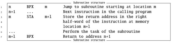
The combination of the initial STA instruction and the final BPX operation is called the return provision. Since subroutines proved to be invaluable tools when it came to slicing complex tasks into smaller units of work, programs emerged which did not do much more than just calling a sequence of subroutines, anticipating the idea of threaded code. Programs of such a structure were called master program, executive routine or sequence selection program.476
12.5 Examples
Nothing is more useful when it comes to understanding a certain computer architecture and its peculiarities, than a number of programming examples. The following code fragments have been taken from [IBM PGM] and [IBM PGM 1959] and show some typical programming techniques used in the days of AN/FSQ-7.477
12.5.1 Polynomial evaluation
The first example program478 is very straightforward and evaluates a polynomial of the form y = ax2 + bx + c for a given set of coefficients a, b, and c and given x by applying HORNER’s479 method. The necessary multiplication operations require some scaling to make sure that no (temporary) result will be outside the allowed range of values given the fixed point number representation scheme of AN/FSQ-7.480
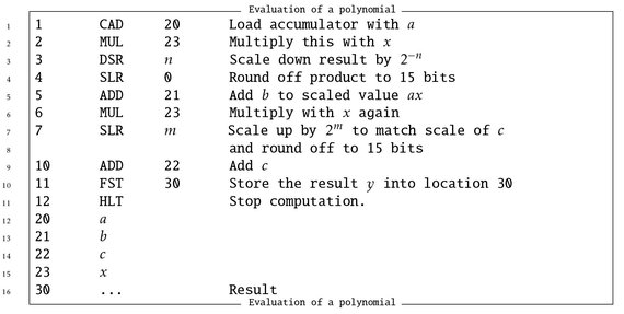
First, the accumulator is loaded with the first coefficient a. Since memory location 20 contains only a 16 bit value, the right accumulator will be set to whatever is in the right half-word of this memory call (normally this would be 0). Accordingly, only the left arithmetic element is used in the remaining program although the right AE could be operated in parallel, performing a second evaluation of a polynomial. The MUL in location 2 computes ax, which has to be scaled down by suitably shifting right with DSR n. The following SLR 0 performs no actual shift operation but rounds off the result.
The next instruction, ADD 21, yields ax + b in the left accumulator, which is then multiplied again by x with MUL 23, followed by a suitable scaling operation since −1 ≤ x ≤ 1 due to the fixed point one’s complement number representation. Adding c finally yields ax2 + bx + c, which is stored in the memory location 30 with FST 30.
12.5.2 Coordinate transformation
The next example program481 shows the benefit of having two arithmetic elements capable of operating in parallel on different data. The task to be solved is the transformation of polar coordinates to Cartesian coordinates, an operation required abundantly in the software running the DCs and CCs.
A radar station located at a known location described by constant Cartesian coordinates xr and yr , with respect to some common point of reference,482 sends a pair of polar coordinates R and ϕ, representing range and azimuth angle, to the DC. These coordinates denote the position of a detected target with the radar station being in the origin of the polar coordinate system. The task is now to determine the target position in Cartesian coordinates xt and yt taking the common point of reference into account:
xt = xr + r cos(ϕ) and
yt = yr + r sin(ϕ).
Such a pair of coordinates could then be used to display the target on a situation console or to guide interceptors to the target.

The first instruction loads the value pair R and ϕ as received from the radar station and stored in memory location 30 into the left and right accumulators. The following CAD-instruction, indexed with the right accumulator according to figure 12.2, performs a table lookup based on the value ϕ to load the values sin(ϕ) and cos(ϕ) required for the actual conversion from polar to rectangular coordinates into the two accumulators. These are then both multiplied by R with TMU 30 and SLR 0, so that the accumulators now hold the rectangular target coordinates R sin(ϕ) and R cos(ϕ) with reference to the radar station. Adding xr and yr with ADD 20 yields the desired coordinates xt and yt, which are then stored into memory location 30 with FST 30.
12.5.3 Finding the largest number
The two example programs above did not need any branches at all. The next program 483 determines the largest of four given values n1,...,n4 requiring a lot of conditional branches while using only the left accumulator again:

The basic idea is straightforward: First the value n1 is loaded into the left accumulator. 484 Then the magnitude of n2 is subtracted from the accumulator by DIM 31. If the result is negative, i. e. n2 ≥n1, the accumulator is overwritten with n2 by branching to the instruction at address 15. If the result is not negative, the branch is not taken and the original value n1 is restored in the accumulator. Instead of loading the accumulator again from memory, the register pair AC-BR is cycled 16 positions to the left485, effectively restoring the original contents of the accumulator since the DIM instruction stores the original contents of the accumulator in the associated B register before performing the subtraction.
The accumulator, now holding either n1 or n2, depending on what value was larger, is then compared against n3 by DIM 32, followed by a conditional branch BLM 17 to address 17 and the same sequence of operations as described above follows. A fourth such sequence eventually leaves the biggest of the four values in the left accumulator.
12.5.4 Adding ten numbers
The next problem involves address modification. The problem to be solved is adding a number of value pairs stored in consecutive memory locations using both arithmetic elements in parallel.486 The first implementation uses address modification, essentially modifying the address part of an instruction during run time:
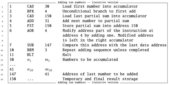
CAD 30 loads the left and right accumulators with the first value pair n1, m1. The following instruction BPX 4 is an unconditional branch to address 4, since no index register is specified, initially skipping the instruction at address 3. The instruction at address 4, ADD 31, then adds the contents of memory location 31 to the accumulators. The following FST 150 stores this (partial) result at address 150 for later use.
The next instruction is unusual from today’s perspective: AOR 4 increments the address part of the instruction stored at address 4, changing it to ADD 32 etc. Since AOR leaves the incremented address in the right accumulator, this can be used to determine if all values have been added already. Subtracting the last address of data stored at address 41 from the right accumulator by SUB 147 yields a negative result if the last value pair has already been added. The BRM 3 instruction accordingly branches back to address 3 only when there are values left to be added. The CAD 150 instruction loads the last partial sum into the two accumulators.
Obviously such a self-modifying program can not be called twice without restoring all altered address parts of its instructions – a serious drawback. In addition to this, using AOR in a place where an index register might have been used is neither overly elegant nor efficient. Accordingly, the AOR was more often used to increment counters stored in right half-words in memory instead of performing address modification.487 The following variant solves the same problem using indexed addressing:

The first instruction, 1 XIN 10, sets index register 1 to the octal value 10 (eight in decimal). The following CAD 30 loads both accumulators with the first value pair stored at address 30. The loop, consisting of the instructions at addresses 3 and 4, first adds the next value pair as addressed by 31 + ir[1]488 by 1 ADD 31 before executing the instruction 1 BPX(01) 3 which requires a bit of attention as it performs two operations at once: First it tests if the contents of index register 1 are positive before subtracting 1 from the index register. If the test for positiveness came out true, a branch back to address 3 is performed.
The first run of this loop adds the value pair stored at address 41489, the next run through the loops adds the contents of address 40 etc. Since the 1 BPX(01) 3 instruction tests the contents of the index register before decrementing it, the loop is actually executed nine times although index register 1 had been loaded with octal 10 initially!
12.5.5 Delaying
In some cases a programmed delay is quite useful. The following program shows a typical routine causing a 120µs delay:490
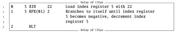
5 XIN 22, which loads index register 5 with the octal value 22, takes 6µs to complete, the tight loop 5 BPX(01) 2 is executed 19 times491, requiring another 6µs per iteration for a total of 120µs.
12.5.6 Printing
The following, last example program sends data to the line printer:492
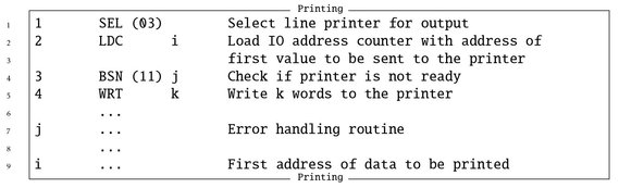
The first instruction selects the line printer as output device. If any previous input /output instruction is still pending as denoted by the IO interlock, the SEL (03) instruction will be suspended until the interlock is cleared. The next instruction, LDC i loads the IO address counter with the address of the first data word to be sent to the printer. Using BSN (11) j, the printer is checked for any error conditions preventing a successful operation.493 The actual data transmission of k data words, which is performed using breakout cycles as described in section 6.3, is initiated with the WRT k instruction.
12.5.7 Trick programs
Every computer, especially a large and complex one as the AN/FSQ-7, invites clever programmers to try things not suggested by the programming manuals. One interesting program that unfortunately has been lost, is remembered by DAVID E. CASTEEL:494
“I once took advantage of the format of the binary load card495 and idiosyncrasies of the instruction language to write a program that could be punched on a single IBM card that would execute and perform a different simple task when read into the computer in each of its 4 possible orientations. (It caused a different one of the 4 condition lights496 to blink on and off depending on which way it was read in.)
I do recall that it depended a great deal on the fact that so many operation codes were essentially [a] NOP497 and so those read backwards were simply ignored. For all practical purposes the card just contained 4 separate 6-step programs, only one of which would actually do anything depending on what orientation it was read in. The layout of the card involved 24 32-bit words in 2 columns [. . . ] with a column of 16 bits left over that was used normally for identification/sequence numbering. When the card was inverted, the null space became the address portion of instructions and all the other half-words had their meanings swapped – addresses became instructions and instructions became addresses; one set of addresses became a new null space, too. The combination of so many NOP instruction codes and the very redundant address scheme for little memory498 made it possible to find codes that could work for either purpose.”499
As short as all of the preceding programming examples are, they give a good impression of the programming techniques used in the 1950s and early 1960s and the intricacies of the AN/FSQ-7 computer architecture with its one’s complement fixed point number representation, dual arithmetic elements and its IO element. The following chapter describes the operational software ran at DCs and CCs.