This chapter shows you how to turn on and turn off lights and appliances at preset intervals or randomly to give a lived-in look to your home while you’re away, program dimmer switches, and control your home entertainment and X10 devices with a single remote. By adding timers, Maxi Controllers, and universal remotes to your existing X10 home automation system, you can turn it into a more powerful and more useful system.
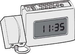
An X10 timer (see Figure 6.1) resembles an alarm clock. However, instead of waking you up, it wakes up specified X10 devices. The Mini Timer shown in Figure 6.1 can control up to eight devices interactively or up to four devices with its built-in timer.

Radio Shack’s Home Automation Starter Kit #61-3000 features a Mini Timer with an LCD display (see Figure 6.2) that can control eight devices interactively or with its built-in timer. It can store up to 64 on or off commands in its built-in memory.
An X10 timer can be used in many ways:
It can turn on or turn off a particular device.
It can dim or brighten a specified incandescent or other dimmable lamp connected to a lamp module or light switch.
It can turn on all lights that use the same house code as the timer and are connected to lamp modules or switches.
It can turn off all devices (lamps and appliances) that use the same house code as the timer.
It can turn on and turn off specified devices on a timed basis.
It can adjust on/off times for all devices controlled by the timer.
You will learn how to use each of these features in the following sections.
Before you install an X10 timer, you need to make sure that you know:
Which devices you want to control
What house code is used by your devices
What unit code is used by each device
What types of modules are used by your devices
You need to identify the devices you want to control so that you can rank them in order of importance. Although you can control up to eight different unit codes interactively with an X10 Mini Timer, you can control only four different unit codes with the timer feature. Therefore, you must decide which devices are most important to control on a timed basis. For example, you might decide that porch lights, the bedroom lamps, and the coffeepot are the most critical devices to you.
A Mini Timer, like any other X10 controller, controls only one house code at a time. If you use multiple house codes in your X10 home automation system, use a different timer for each house code you want to control.
You need to identify the unit codes used by your devices. Mini Timers can control only unit codes 1–4 and 5–8. Timers that can control unit codes 9–16 are not widely available at the present time. Therefore, you must adjust the unit codes on the modules, outlets, or switches you want to control with a Mini Timer to fall into one number range or the other, or purchase and configure an additional Mini Timer. If you need to control devices with unit codes higher than 8, consider using a tabletop Maxi Controller (see the “X10 Tabletop Maxi Controller” section later in this chapter) or a computer-based controller (see Chapter 11, “Accessing X10 Home Control via Your Home Computer,” for details).
The module type(s) you use in your automation system are also important if you want to make full use of the All Lights On button. This button triggers lamp modules and light switches, but does not control appliance modules or outlets. However, the All Units Off button turns off all types of X10 modules, including appliance modules and outlets as well as lamp modules and light switches. Use Table 6.1 to plan your Mini Timer home automation project. Table 6.2 provides a completed sample for your review.
Table 6.2. Sample Timer Planning Sheet
House Code | Unit Code | Device Type | Location | Module Type | Control with Timer? |
|---|---|---|---|---|---|
B | 2 | Porch light | Front Porch | Lamp | Yes |
B | 3 | TV | Bedroom | Appliance | Yes |
B | 5 | Porch light | Back Porch | Lamp | Yes* |
*Change to unit | |||||
code 2 | |||||
B | 4 | Coffee maker | Kitchen | Appliance | Yes |
C | 1 | Ceiling light | Bedroom | Lamp | Yes* |
*Change to house | |||||
code B | |||||
C | 2 | Motion detector | Garage | Specialized | No |
C | 3 | Wireless camera | Garage | Specialized | No |
As you can see in Table 6.2, inventorying your existing X10 modules can be very useful before installing an X10 timer. Note that the back porch light must be moved to unit code 2 to enable it to be controlled by the same timer as other appliances. Also, the house code used for the ceiling light in the bedroom must be changed to B from C to enable it to be controlled by the timer. The security devices in the garage could be controlled by a separate timer, or not timer-controlled at all as in this example.
To adjust the unit or house code for a plug-in module with control dials, use a small screwdriver as shown in Figure 6.3.

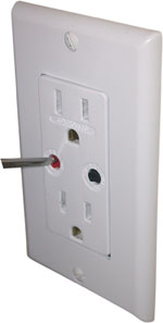
To adjust the unit or house code for an electrical outlet with control dials, use a small screwdriver as shown in Figure 6.4.
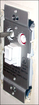
To adjust the unit or house code for a light switch with control dials, you have to remove the switchplate, and then use a small screwdriver as shown in Figure 6.5.
If you use modules or light switches that are programmed with code sequences, you will need to use a Maxi Controller or a computer interface to configure them. To learn how to use a Maxi Controller, see the “X10 Tabletop Maxi Controller” section, later in this chapter. Computer interfaces are discussed in Chapter 11.
Before you plug in your Mini Timer, flip it over and install the appropriate battery in the base. The X10 Mini Timer uses a nine-volt alkaline battery in the base (see Figure 6.6). The Radio Shack Mini Timer shown in Figure 6.2 uses a pair of AA batteries. Batteries provide backup power to maintain settings if the unit is unplugged or an AC power failure takes place.

To install a Mini Timer, simply plug it into an AC electrical outlet. Remember, as with any X10 device, don’t plug it into a surge suppressor; surge suppressors prevent X10 signals from being transmitted reliably.
To set the current time with either the X10 or Radio Shack Mini Timer, select Set Clock with the Mode Switch slider (see Figure 6.7) and use the Time buttons to advance to the correct time. After you’ve selected the correct time, move the mode switch to Run.

Figure 6.8 shows the control panel of the Radio Shack Mini Timer illustrated in Figure 6.2. Compared to the X10 Mini Timer, the Radio Shack Mini Timer does not provide bright/dim control for lamp modules, but other interactive control options are similar.
When the mode switch on the Mini Timer is set to Run, the Mini Timer can be used like any tabletop or wireless X10 remote. Press the On button for the unit code of the device you want to start, and the device turns on; press the Off button to turn it off (refer to Figures 6.7 and 6.8).
To turn on all lights using the same house code as the timer, press the All Lights On button with either Mini Timer. To turn off all modules using the same house code as the timer, press the All Units Off button (refer to Figures 6.7 and 6.8).
To adjust the brightness of a particular lamp with the X10 timer, press the On button that corresponds to that lamp’s unit code, and then press the Dim or Bright button (refer to Figure 6.7) until the lamp reaches the desired brightness level.
After you’ve used interactive control to make sure that your timer can communicate with your modules, it’s time to learn how to use timed control. Timers can trigger devices to turn on or turn off at the same time every day, just once, or at random times within the hour selected (Security mode).
In this example, let’s program porch lights on unit code 2 to come on at 6:00 p.m. and turn off at 11:30 p.m. every day. To adapt this procedure to your use, replace the unit codes and times with those suitable for your situation. The steps are the same for the X10 and Radio Shack Mini Timers.
Make sure that the porch lights are set to the same house code as the timer and to unit code 2 (refer to the “Preparing to Use an X10 Timer” section earlier in this chapter for details).
Move the Mode Switch slider to Prog Set (see Figure 6.9).
Press the Time button to advance the time to 6:00 p.m.
Press the On button for unit code 2. The display blinks momentarily. This sets the On time for 6:00 p.m.
Press the Time button to advance the time to 11:30 p.m.
Press the Off button for unit code 2 to shut off the unit at 11:30 p.m.
Set the Mode Switch slider to Run.
The porch light will come on at 6:00 p.m. and turn off at 11:30 p.m.
With the X10 Mini Timer, you can store two on and two off commands for each unit code. Therefore, you can also turn on the porch lights in the morning. To turn on the porch lights at 5:30 a.m. and off at 8:00 a.m., follow the same procedure, but substitute 5:30 a.m. for 6:00 p.m. in step 3 and 8:00 a.m. for 11:30 p.m. in step 5.
After you’ve stored both sets of commands, the porch lights will come on at 5:30 a.m. every day, shut off at 8:00 a.m., come on again at 6:00 p.m. every evening, and shut off at 11:30 p.m. each night.
You can store up to 64 on or off commands in the memory of the Radio Shack Mini Timer. There is no restriction on the number of commands that can be stored for each unit code.
The X10 Mini Timer used in this chapter displays 18:18 in the time display window if you attempt to create a third on or off event for a particular unit number. To clear 18:18 from the display, move the mode switch to Prog Review and press the On or Off button for the unit code you tried to program with a third event. This puts the unit into Review mode.
The Radio Shack Mini Timer displays Full in its LCD display if you attempt to store more than 64 commands. To clear a command, press the number of the unit code you want to remove, press the On or Off button, and then press the Clear button (refer to Figure 6.9).
If you want to set a timed event to occur just once, you can do so by pressing the Once button during the programming process with the X10 Mini Timer. For example, let’s assume that you want to turn on your Christmas tree at 5:00 a.m. on Christmas Day to greet the children as they hurry down the stairs. Follow this procedure any time after 5:00 a.m. on Christmas Eve:
Make sure that the module used for the Christmas tree is set to the same house code as the timer and that you know the unit code. In this case, we’ll use unit code 1.
Move the Mode Switch slider to Prog Set (see Figure 6.10).
Press the Time button to advance the time to 5:00 a.m.
Press the On button for unit code 1, and then press the Once button (see Figure 6.10) within four seconds. The display blinks momentarily. This sets the Christmas tree to turn on at 5:00 a.m. the next morning.
Set the Mode Switch slider to Run.
At 5:00 a.m., the Christmas tree will turn on automatically. If you really want to surprise the kids, choose a time after they’re likely to be up.
With the Radio Shack Mini Timer, follow steps 1–3 as listed. In step 4, press the Mode button instead of the Once button and hold it down until “Once” shows on the LCD display. Follow step 5 as written.
To check your settings, move the Mode Switch slider to Prog Review (Prog. Set/Review on the Radio Shack Mini Timer). Press any On or Off button to see events programmed for that unit code: The time display shows the on or off time if an event has been programmed. To see whether a second on or off time has been programmed, press the On or Off button again. To remove a timed setting, press the Clear button while viewing an on or off time. After you’ve finished reviewing or deleting settings, set the Mode Switch slider to Run.
To vary the exact on and off times for a particular module, press the Security button on the X10 timer within four seconds after you select On or Off during programming. For example, to vary the exact times the porch lights come on, follow this procedure:
Make sure that the porch lights are set to the same house code as the timer and to unit code 2 (refer to the “Preparing to Use an X10 Timer” section earlier in this chapter for details).
Move the Mode Switch slider to Prog Set (see Figure 6.11).
Press the Time button to advance the time to 6:00 p.m.
Press the On button for unit code 2 and press the Security button within four seconds (see Figure 6.11). This sets the actual on time to vary within the hour of 6 p.m.
Press the Time button to advance the time to 11:30 p.m.
Press the Off button for unit code 2 to shut off the unit at 7:00 a.m. and press Security within four seconds. This sets the actual off time to vary within the hour of 11 p.m.
Set the Mode Switch slider to Run.

With the Radio Shack Mini Timer, follow steps 1–5 as written. In step 6, repeatedly press the Mode button within four seconds (instead of the Security button) until “Security” is displayed. Follow step 7 as written.
Use the Sleep button (see Figure 6.12) to turn on or turn off a particular unit code for 15 minutes or multiples of 15 minutes. To turn on a device for 15 minutes, press the On button for the device’s unit code, and then press the Sleep button within four seconds. Press the Sleep button twice to turn it on for 30 minutes, and so forth. To turn off a device for 15 minutes, press the Off button for the device’s unit code, and then press the Sleep button within four seconds. Press the Sleep button twice to turn it off for 30 minutes, and so forth. Up to two unit codes can be operated in Sleep mode at the same time. The Radio Shack Mini Timer does not support Sleep mode.
The Wake Up slider switch (see Figure 6.12) triggers a buzzer when an On command is sent to unit code 1 or unit code 5. You can use this feature to make your Mini Timer function as an alarm clock. For example, connect your bedroom lights to a module set for unit code 1 or unit code 5, set unit code 1 (or 5) to receive an On command at 6:30 a.m., and if Wake Up is turned on, the bedroom lights will come on at 6:30 a.m. and the Mini Timer will sound a buzzer. On the Radio Shack Mini Timer, the Wake slider switch performs the same function.
On weekends, leave Wake Up turned off and the buzzer will not come on. To shut off both the buzzer and the module on unit code 1 or unit code 5, move the buzzer switch to Off and move the Mode switch to Set Clock. At the end of the weekend, move the Wake Up switch to On (doing so re-enables the buzzer) and the Mode switch back to Run (the module on unit code 1 or 5 will turn on as scheduled next morning). On the Radio Shack Mini Timer, use the Clock Set position instead of Set Clock to turn off wakeup functions.
When the buzzer sounds and the device on unit code 1 (or 5) is triggered, press any key on either Mini Timer to snooze (turn off) the buzzer for 10 minutes. The device triggered remains on.
Caution

Just because a controller fits on a table and plugs into the wall doesn’t mean it supports programmable devices. If the controller uses On/Off buttons for each unit code, it can’t be used to control multiple devices or send commands. Mini controllers have Unit Code On and Unit Code Off buttons, whereas Maxi Controllers have Unit Code buttons and separate On and Off buttons. This enables the Maxi Controller to send an X10 address without a command (A10) instead of sending an address with a command (A10 On or A10 Off) as a Mini Controller or Mini Timer does.
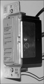
As you’ve learned in the preceding sections, adding a Mini Timer to your X10 home automation system provides true automation. You no longer need to turn on or turn off lights or other devices manually or with a remote control. However, a Mini Timer is not designed to control multiple devices interactively or to send strings of program codes to intelligent dimmer switches. If you have one or more programmable dimmer switches, or if you want to control groups of devices, you need to add a full-featured X10 tabletop controller (see Figure 6.13), often referred to as a Maxi Controller, to your home automation system.

Like a Mini Timer, the X10 tabletop controller shown in Figure 6.13 can turn on all lights and shut off all units. However, it differs in two significant ways from a Mini Timer or wireless remote control:
It can control all 16 available X10 unit codes.
It has separate buttons for unit codes and for commands (on, off, bright, dim).
These features enable you to control multiple devices with a single set of commands and send combinations of house codes and unit codes to control programmable X10 dimmer switches, such as the one shown in Figure 6.14. To learn how to install this type of light switch, refer to Chapter 4, “Using X10 to Control Home Lighting.”
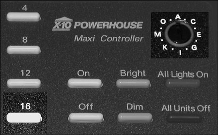
To set up a Maxi Controller, follow this procedure:
Determine the house code used by the devices you want to control.
Turn the House Code dial (see Figure 6.15) to the house code used by those devices.
Plug the controller into an AC outlet, not a surge protector.
Some vendors supply stickers that you can use to indicate the type of module and location for each unit code. Don’t apply these stickers right away; instead, keep notes on a separate piece of paper until you’ve completed your project.
To control a single device, press the unit code number for that device, and then the command key (refer to Figure 6.15). For example, to turn on a lamp connected to a module at unit code 1, press the 1 button, and then press the On button. To turn off the lamp, press 1, and then press the Off button.
To control multiple devices at the same time, press the unit code number for each device, followed by the command key. For example, to turn on lamps connected to modules at unit code 1 and unit code 2, press 1, 2, and then press the On button. To turn off the lamps, press 1, 2, and then press the Off button.
You can also dim or brighten two or more lights at the same time. For example, to dim lamps on unit codes 1 and 2, press 1, 2 and then press Dim until the desired brightness level is reached.
The All Lights On and All Units Off command buttons (refer to Figure 6.15) work the same way on a tabletop Maxi Controller as on the X10 Mini Timer discussed earlier in this chapter:
Press the All Lights On button to turn on all lights connected to X10 lamp modules or light switches using the same house code as the controller.
Press the All Units Off button to turn off all X10 devices (including lights and appliances) using the same house code as the controller.
If you plan to install programmable dimmer switches or modules to your X10 home automation system, adding an X10 tabletop Maxi Controller should be on your “must buy” list. Its capability to send combinations of house and unit codes to a programmable dimmer switch or module is essential, especially if you are not ready to add computer control to your X10 home automation system.
Before you can send commands to the dimmer switch or module, make sure that you have the instruction manual for the switch or module (you can usually obtain electronic versions in Adobe Acrobat format from the vendor). The instruction sheet lists the codes you need to send to program preset dimming levels, dimming rates, and other advanced features, as well as the method used to program house and unit codes for the device.
You’ll need to keep a small screwdriver handy because many modules use different house and unit code combinations for some types of programs. You must change the house code frequently when sending strings of commands. Here are some examples based on commands used by ToggleLinc and SwitchLinc programmable dimmer switches made by Smarthome (www.smarthome.com).
To prepare the switch or module to accept programming commands, send the following codes with the tabletop Maxi Controller: O16, N16, M16, P16, M16.
To send these commands, follow this procedure (see Figure 6.16):
Turn the House Code dial to O.
Press the 16 key.
Turn the House Code dial to N.
Press the 16 key.
Turn the House Code dial to M.
Press the 16 key.
Turn the House Code dial to P.
Press the 16 key.
Turn the House Code dial to M.
Press the 16 key.
Turn the House Code dial back to the normal house code used (for example, B).
To set the switch or module to turn on at a preset dimming level, press the Unit Code button for that switch, followed by the Dim button. Release the Dim button when the lamp is at the appropriate brightness. Then send these commands to store this level: O16, P16, N16, M16.
To send these commands, follow this procedure:
Turn the House Code dial to O.
Press the 16 key.
Turn the House Code dial to P.
Press the 16 key.
Turn the House Code dial to N.
Press the 16 key.
Turn the House Code dial to M.
Press the 16 key.
Turn the House Code dial back to the normal house code used (for example, B).
When you turn on the switch or module, the lamp connected to it will turn on at the brightness level stored in memory. Scene-capable dimmer switches store scenes and bright/dim ramp rates the same way.
Many, but not all, programmable light switches and modules are also capable of storing a scene. Switches and modules with this feature are sometimes referred to as scene-capable. An X10 scene is a particular action (such as dimming the light to a particular level at a particular rate or turning on a fan) that is assigned its own house and unit code; think of it as a sort of macro. You can create scenes with a tabletop Maxi Controller as described in this section, or with an X10 computer interface (see Chapter 11).
The specifics of how to create a scene vary with the programming codes understood by the module or light switch. The examples in this section, like those in the previous section, are based on the codes supported by ToggleLinc, SwitchLinc, and other Smarthome products. If you use other brands of scene-enabled modules or switches, consult the documentation for your product for details.
To prepare the module to receive a new scene, enter these commands: O16, N16, M16, P16, M16.
To send these commands, follow this procedure:
Turn the House Code dial to O.
Press the 16 key.
Turn the House Code dial to N.
Press the 16 key.
Turn the House Code dial to M.
Press the 16 key.
Turn the House Code dial to P.
Press the 16 key.
Turn the House Code dial to M.
Press the 16 key.
Turn the House Code dial back to the normal house code used (for example, B).
Let’s assume that the unit code for the switch is 2. To create a scene with a low light level, press 2 on the controller, and then press the Dim key and release it when the light level reaches the desired level. To store that level as a scene, send the following commands, followed by the unit code you want to use to identify that scene.
The scene commands are M16, N16, O16, P16.
To send these commands, follow this procedure:
Turn the House Code dial to M.
Press the 16 key.
Turn the House Code dial to N.
Press the 16 key.
Turn the House Code dial to O.
Press the 16 key.
Turn the House Code dial to P.
Press the 16 key.
Turn the House Code dial back to the normal house code used (for example, B).
Finally, send the unit code you want to use to identify the scene. Make sure that you don’t use an existing unit code. For example, if house code B is already controlling unit codes 1–6, you could use any unit code from 7–16. If you want to use a Mini Timer or Mini Controller to control the scene, make sure that you assign it a unit code from 1–8. However, if you plan to use a Maxi Controller or wireless remote that supports all unit codes 1–16, you can assign any unit code to the scene.
For example, to use B16 as the code for this scene, do the following:
Make sure that the house code is set to B.
Press the 16 button.
To activate the switch or module in its normal mode, follow these steps:
Make sure that the house code is set to the correct value (B, in this example).
Press the button for the module’s normal unit code (2, in this example).
Press On, Off, Bright, or Dim.
To activate the scene, do the following:
Make sure that the house code is set to the correct value (B, in this example).
Press the button for the scene code (16, in this example).
Press On to activate the scene.
Most scene-enabled modules can store multiple scenes. For example, the SwitchLinc two-way switch I installed can support up to 64 scenes. Check with the vendor of the switch or module you’re considering to determine how many scenes a particular model can store. Each scene must use a unique house/unit code combination.
Caution
As you can see from the examples in this chapter, certain house and unit codes are reserved by programmable modules and switches for sending and storing commands. Do not use these house and unit codes for other devices. The easiest way to avoid conflicts is to avoid using the house codes used for programming with any of your devices. For example, with Smarthome devices, you might want to avoid using house codes M, N, O, and P. Consult the documentation for other brands to determine which house and unit codes are reserved for configuring programmable modules.
Use Table 6.3 to record scene settings you create. Table 6.4 shows a completed sample.
If don’t want to add yet another remote to your growing collection of them and you use X10 interactively, consider using a universal remote that can control both X10 devices and some, or all, of your home entertainment devices.
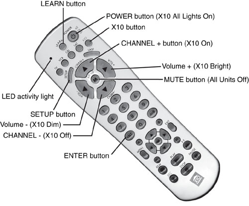
At first glance, this might seem to be an impossible requirement. After all, X10 uses commands sent via AC power line signals, whereas home entertainment devices use infrared (IR) line-of-sight signals. However, by using a remote control capable of sending X10 and home entertainment signals (see Figure 6.17), you can control both types of devices with a single remote control.
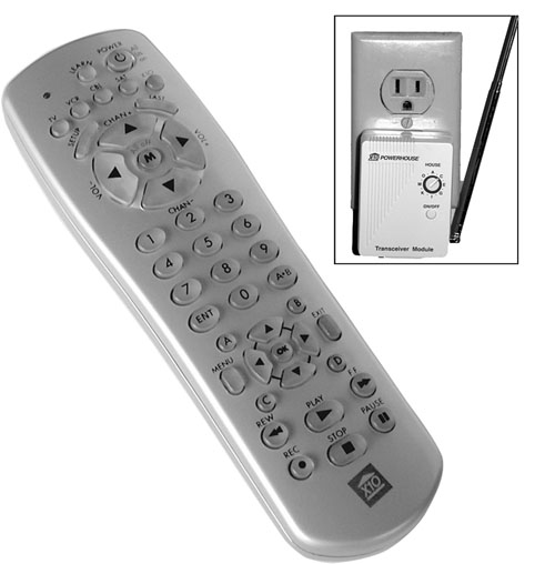
To set up a typical universal remote for use with your home entertainment hardware, such as the UR74A 5-in-1 Universal Learning Remote shown in Figure 6.17, install the appropriate batteries, and then use the code listing supplied with the remote or use the learning feature.
Here’s how to teach the remote to control your electronics:
Turn on the TV or other electronic device you want to control with the universal remote.
Press and hold the SETUP button (see Figure 6.18) until the red LED indicator light glows steadily.
Release the SETUP button.
Press and release the mode button for the device you want to control. For example, to control a TV, press the TV button.
Enter the three-digit code from the library code table for the device. After you’ve entered the last digit, the red LED will turn off.
Point the remote at the device and press POWER. If the device turns off, continue to the next step.
Point the remote at the device and press POWER to turn the device on again.
Press CHANNEL +. If the device responds, you have successfully programmed your remote to use that device.
If the device does not work at step 7 or step 8, start the process over again with the next code number for the brand of device. For other types of X10 universal remotes, see the instructions packaged with the remote.
Use the learning feature to teach the universal remote any codes it did not receive from the code used to configure basic features. For example, if you find a code that supports all of your television’s features except the FM radio button, you can use the learning feature on the new remote to understand the FM command: Transmit the FM radio command from your original remote to the learning remote while you select an unused button for configuration as the FM radio button.
Right out of the box, the remote is ready to work with X10 devices using house code A. To change house codes, follow this procedure:
Press the X10 button (refer to Figure 6.18).
Press and hold the SETUP button until the LED (light emitting diode) activity light above the TV and VCR button blinks.
Enter the number corresponding to the house code from Table 6.5. For numbers 1–9, press the number key. To enter numbers 10–16, press each digit. To enter 10, press 1, and then press 0, and so on.
Press the ENTER button to store the new house code.
After you’ve configured your remote to work with your television and other home entertainment devices, it works like any other universal remote. Press the button for the device you want to control, such as the TV, and then press the button for the command you want to send. For example, to turn on the TV and switch it to channel 7, use this procedure:
Press the TV button.
Press the POWER button.
Press the 7 key on the keypad.
Press ENTER (if necessary; required by some types of TVs).
If you are unable to control all the features of your home entertainment device with the universal remote, try these solutions:
Try a different device code from the list for your brand of home entertainment hardware.
Contact the vendor to determine the correct remote code for the device. The Universal Remote Codes website at www.xdiv.com/remotes/ is a helpful place to start your search; you can also try searches on Google (www.google.com) and other Internet search engines.
Use the universal remote’s learning feature to learn specific commands from the device’s original remote control (if you have it).
Keep the original remote control handy (if you still have it) in case you need to use it for specific situations.
The 5-in-1 X10 Universal Learning Remote is preprogrammed to work with an X10 RF transceiver such as the one shown in Figure 6.17. To control an X10 device, do the following:
Press the X10 button on the remote control.
Press the unit number of the device you want to control. For example, if you want to control a device using unit code 11, press the 1 key twice.
To turn on the unit, press the CHANNEL + button. To turn off the unit, press the CHANNEL - button.
To dim a lamp connected to a lamp module or switch, press the VOLUME - button. To brighten it, press the VOLUME + button.
To turn on all lamps connected to lamp modules or switches on the same house code, press the POWER button.
To turn off all X10 modules (including appliance modules) on the same house code, press the Mute (M) button.
If you don’t have an RF transceiver in your X10 home automation system, you can also use an X10 universal remote with an IR-based tabletop controller such as the X10 IR543 Command Center (see Figure 6.19). It plugs into an AC electrical outlet, just as with the other devices discussed earlier in this chapter. It can control unit codes 1–4 or 5–8 interactively (you select the device numbers with a top-mounted selector switch), and you can control groups of devices, just as with an X10 Maxi Controller. You can control unit codes 9 and 10 through IR signals. However, because it lacks buttons for unit codes 9–16 and cannot send IR signals to unit codes above 10, it cannot be used to configure programmable modules or switches.

Although the Command Center can be used as a tabletop controller, its primary function is to receive IR signals from an X10 universal remote control. Although some vendor websites suggest that you need one of these to enable your X10 universal remote to work properly, you can do without this device if you already have an RF transceiver and your X10 universal remote can send RF signals, as the 5-in-1 model shown earlier in this chapter can do.
Consult the instructions for your X10 universal remote to determine whether you need to reconfigure it to work with an X10 IR controller. For example, the UR74A must be reprogrammed from device code 999 (X10 RF transceiver) to code 998 to use the IR543.
To reprogram your X10 universal remote to work with the IR543, follow this procedure:
Press and hold the SETUP button until the LED indicator lights steadily (refer to Figure 6.18).
Release the SETUP button.
Press and release the X10 button.
Press 9, 9, 8 and then press the ENTER button. This programs the remote to control the IR Mini Controller.
To reprogram the controller to work in standard mode, follow the same instructions but, in step 4, press 9, 9, 9, and then press the ENTER button.
If you want to use the X10 Universal Remote with both a wireless transceiver and the IR543, program an unused device type button (except the TV button) on the remote to use code 998 (the code for the IR543).
Table 6.6 compares the control options available with the X10 Universal Remote when used with a wireless transceiver and with the IR543 IR Mini Controller.