
If X10 home automation is smart enough to control your lighting, is it smart enough to help you heat and cool your home? The answer is “Yes!” Whether you’re interested in adding interactive control to a whole-house fan, an automatic feature to central heating and air, or a thermostatic control to portable heating and cooling devices, this chapter shows you how X10 home automation can help you save money and help make your life easier.
You can use X10 to view and control your home’s heating, ventilating, and air conditioning (HVAC) in a variety of ways:
Temperature monitors can be used to detect the temperature in different rooms.
Thermostats can be used to control HVAC interactively or from your computer desktop. By adding telephone (see Chapter 10, “Accessing X10 Home Control via Telephone”) or web-based (see Chapter 12, “Accessing X10 Home Control via Your Home Network and the Internet”) remote access, you can literally turn up the heat or the AC from anywhere.
You can replace your existing HVAC controller with an X10 PLC–based unit.
The following sections discuss the various approaches in greater detail.
One big problem with typical household thermostats is that they measure heat at just one location: the thermostat itself. If the thermostat is in an unusually hot part of the house (such as a location that receives direct sun for part of the day), the remainder of the house will be chilly in all seasons. The heat won’t run much in the winter, and the air conditioning will be blasting away in the summer.
You can use X10 temperature monitors to determine the temperature variations in different parts of your home and apply this information in a variety of ways. If your home has zone heating or AC, you can adjust the heating or cooling in different rooms based on this information. If parts of your home are subject to potentially dangerous temperature extremes, you can monitor these locations and receive a warning of low temperatures before damage (such as frozen water pipes) can take place. Temperature monitors can also be used to provide thermostatic control of portable heating and cooling devices; see the “Using X10 Control for Heating and Cooling Appliances” section later in this chapter.
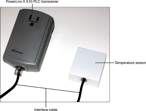
The Smarthome TempLinc model 1625 (shown in Figure 7.1) is a leading X10 temperature monitor. It has three components:
A temperature sensor; this is a small box that can be attached to a wall or other location with double-stick tape or screws (both included).
An X10 transceiver, which is a modified version of the Smarthome PowerLinc II; this plugs into an AC outlet.
An interface cable to connect the sensor and the X10 transceiver.
TempLinc can be programmed to monitor temperatures and transmit changes as frequently as they occur or only on request. When an X10 HVAC control is added to the HVAC system, TempLinc also can be used as a thermostat to provide heating and cooling control. TempLinc can be configured to work in Fahrenheit (F) and Celsius (C) temperature scales.
Table 7.1 lists the codes supported by TempLinc; these are the same codes used by the popular RCS family of programmable X10 thermostats.
Table 7.1. Programming Codes Used by TempLinc and RCS Programmable Thermostats
Operation Mode | Code (Fahrenheit) | Code (Celsius) | Examples |
|---|---|---|---|
Reports when temperature changes | House code +1 | House code +9 | B1, B9 |
Reports on user request | House code +2 | House code +10 | B2, B10 |
Thermostat mode (cooling) | House code +3 | House code +11 | B3, B11 |
Reports when temperature changes and thermostat cooling mode combination | House code +4 | House code +12 | B4, B12 |
Reports on user request and thermostat cooling mode combination | House code +5 | House code +13 | B5, B13 |
Thermostat mode (heating) | House code +6 | House code +14 | B6, B14 |
Reports when temperature changes and thermostat heating mode combination | House code +7 | House code +15 | B7, B15 |
Reports on user request and thermostat heating mode combination | House code +8 | House code +16 | B8, B16 |
Use these codes to configure the TempLinc as described in the following section.
To program the TempLinc’s house and unit code:
Plug a Maxi Controller into an AC outlet other than the one used for the TempLinc; this will be used to program the TempLinc.
Plug the TempLinc transceiver into another AC outlet.
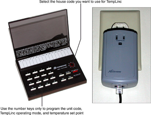
Within one minute of plugging in the TempLinc transceiver, send the same house/unit code three times in a row using the Maxi Controller. For example, to use F2 for the TempLinc, press the F, 2, F, 2, F, 2 keys on the Maxi Controller (shown in Figure 7.2). For more information about the Maxi Controller, refer to Chapter 6, “Using Timers and Advanced Remotes for X10.”
4.Using the Maxi Controller, send the same house code you used in step 3 and a unit code that corresponds to one of the modes in Table 7.1. For example, to set TempLinc to operate in the Report on Change mode, press the F, 1 keys (assuming that the TempLinc is using house code F as in step 3).
If the TempLinc will be used as a thermostat to control an HVAC system or other heating/cooling device, you must also program the temperature setpoint. The setpoint is the temperature you’d like to maintain. The setpoint is sent in two pieces: as the first digit (tens) and the second digit (ones). For example, to set the setpoint to 72° Fahrenheit using a house code of F, you’d send F7 F2 (F7 = 70, F2 = 2).
Although each programming step has been written down separately in this section for clarity, you should actually send the codes in quick sequence to avoid the TempLinc timing out or receiving erroneous X10 commands from another source. For example, to program TempLinc to be identified as F2 in your system and to work in Report on Change mode, send these codes in sequence:
F2 F2 F2 (Sets house/unit code)
F1 (Sets operating mode)
To program TempLinc to be identified as B6 in your system and to work as a thermostat (Cooling mode) with a setpoint of 68° Fahrenheit, send these codes in sequence:
B6 B6 B6 (Sets house/unit code)
B3 (Sets operating mode)
B6 B8 (Sets temperature setpoint)
As you have learned in previous sections, the X10 protocol can transmit house codes, unit codes, and preset dim levels. These three elements of the protocol are used by TempLinc and other types of X10 or X10–compatible temperature sensing and thermostat devices to report the current temperature.
TempLinc uses unit codes 11–16 in the selected house code, along with preset dim levels, to report the current temperature when the temperature changes or the unit is queried. TempLinc’s documentation includes a translation table in which you can look up the house code and preset dim level transmitted by TempLinc to determine the correct temperature in Fahrenheit or Celsius. Refer to TempLinc’s instructions for more detail.
If your home computer is configured to connect to your X10 system with an interface, you might be able to see the temperature on your computer screen. X10 PLC-compatible software programs such as Smarthome Live! (see Chapter 12), HomeSeer (see Chapters 11, “Accessing X10 Home Control via Your Home Computer,” and 12), and many others can read this information and translate it into a user-friendly display. However, even if your software cannot translate the codes for you, you still can set the interface to report on request, query the house and unit code, and receive the unit code and preset dim value. Look up this information in the translation table provided with TempLinc to determine the current temperature.
You can use TempLinc in Thermostat mode to
Control X10 PLC HVAC systems
Control small heaters, fans, and window AC units
To learn more about controlling portable heaters, fans, and window AC units, see “Using X10 Control for Heating and Cooling Appliances” section later in this chapter.
If you want to use X10 to help control your HVAC system but don’t want to go to the trouble and expense of replacing the thermostat and HVAC control system, you still can use X10 to save on your heating bills by installing an X10 PLC thermostat setback module, such as the X10.com TH2807 (shown in Figure 7.3). The TH2807 is sold by many X10 hardware vendors, and sells for about $20 (or about one-tenth the cost of a full-blown X10 HVAC control system).
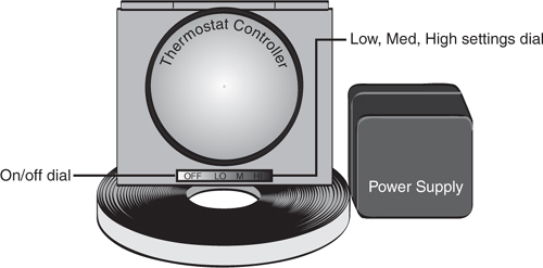
The TH2807 installs on the wall below your normal thermostat and is plugged into a standard X10 appliance module (refer to Chapter 5, “Using X10 to Control Appliances,” for examples). The TH2807 has a simple sliding control that enables you to select a temperature reduction of about 5° (low), 10° (medium), or 15° (high) when the unit is triggered. When the TH2807 activates, a small heater inside the unit is turned on. Heat from the heater is picked up by your thermostat, making the thermostat “think” that the room is warmer than it actually is. Because the thermostat thinks the room is warmer, it doesn’t turn on the heat as often as usual. For example, you can leave your thermostat set to a comfortable 72° at all times, but when the TH2807 is activated, the room will be up to 15 degrees cooler, depending upon how the unit is set. Figure 7.4 demonstrates how the TH2807 works.
You can also use the TH2807 in the summer if your home has central air conditioning: When the unit is triggered, the small heater comes on and warms the thermostat, which obediently turns on the air-conditioning unit.
Because the TH2807 is controlled by an standard X10 or X10–compatible appliance module, it can be triggered by a wireless X10 remote control and transceiver as you saw in Chapter 5, a tabletop Mini Timer or Maxi Controller as shown in Chapter 6, a security system as you’ll see in Chapter 9, “Using X10 to Provide Security,” or by a home computer interface (see Chapter 11) or web-based interface (see Chapter 12).
The TH2807 is best suited for use with a traditional nonprogrammable thermostat. If you prefer to combine the power of a programmable thermostat with full remote capabilities, you need to consider an X10 HVAC controller and thermostat combination.
The ultimate in X10 home climate control involves replacing your existing thermostat with an X10 thermostat and connecting an X10 controller to your existing furnace and air conditioning system. This solution enables you to control and monitor your HVAC very precisely via telephone, home computer, and Internet, and support a full range of day and time programmability as well as the latest multistage HVAC systems and heat pumps.
Some of the most widely supported X10-compatible HVAC controllers and thermostats are those made by Residential Control Systems, Inc. (RCS). The latest RCS product for X10 HVAC control is the TXB16 thermostat and controller, which replaces the popular TX15-B model. The TXB16 thermostat and controller are used in this chapter to show how X10 can be used to control an HVAC system.
The TXB16, like its predecessor, has two major components:
A Wall Display Unit, which replaces the standard or programmable thermostat
An HVAC Control Unit, which is connected directly to your HVAC system and to the Wall Display Unit
Other parts of the TXB16 kit include
A TW523 X10 interface used by the HVAC Control Unit
An RJ-11 cable to connect the TW523 to the HVAC Control Unit
A 12V DC power “brick” that connects the HVAC Control Unit to a 115-volt outlet
Figure 7.5 shows how the TXB16’s components are retrofitted to a typical HVAC system.
The TXB16 Control Unit is connected to the HVAC system using the wiring that originally ran to the thermostat. In effect, the TXB16 Control Unit replaces the temperature control functions of the original thermostat, and the TS16 Wall Display Unit replaces the display and user interface functions of the original thermostat.
Caution

You can make a real mess of your HVAC system if you don’t properly install HVAC thermostats and controllers. Although most projects in this book are suitable for nonexpert installation, so many variations are possible in HVAC systems that it’s easy to make a mistake. For this type of installation, you might want to hire an HVAC specialist—particularly one experienced in X10 installations. However, if you prefer to do it yourself, check the following:
Find out from your builder or HVAC contractor the details of your HVAC system
If you’ve previously replaced a thermostat, take a look at how it’s wired. You’ll make the same types of connections to the TXB16 Control Unit.
Note the wire colors used by your thermostat and their connections. They might not match the standards listed in the TXB16 Control Unit documentation. For example, my home uses a blue wire for the fan rather than the normal green wire.
Use a digital camera set for close-up mode to photograph the wire connections in your current thermostat before you disconnect it.
Before you install the TXB16 Control Unit or any other HVAC controller, you should determine what type of heating system is already in place:
Conventional gas or electric heating or heat pump
Integrated or separate heating and cooling systems
Single-stage or two-stage heating or cooling
Each of these affects the jumper settings and wiring connections used on the TXB16. Figure 7.6 shows the location of the wiring blocks and DIP (dual inline package) switch bank inside the TXB16 Control Unit.
Proper configuration of the TXB16 Control Unit requires you to do the following:
Correctly wire the connection between the existing HVAC unit and the J5 seven-screw wire connector on the TXB16 Control Unit. This should essentially be wired the same way as your current thermostat’s heating, cooling, and fan wires (see Figure 7.7) .
Properly configure the SW1 bank of DIP switches to match the type of system (gas, electric, or heat pump), the matching X10 decode table, and heat pump changeover settings. See Table 7.2 for a quick reference (right = on; left = off).
Table 7.2. SW1 DIP Switch Quick Reference (TXB16 Control Unit)
Additional DIP switches should be ignored.
The four-screw J1 connection is used for the connection to the TS16 Wall Display Unit (discussed in the next section). J2 is used for the connection to the TW523 or equivalent X10 interface included with the kit, and J4 is a connection to the 12V DC transformer (also included with the kit).
The TS16 Wall Display Unit is used in place of a standard or programmable thermostat. Remove the LCD display and pushbutton front panel to reveal the wiring connectors. The J1 connector on the right side is used for the four-wire connection from the TXB16’s J1 connection, whereas the J2 connector on the left side is used for an optional RS15 remote sensor (see Figure 7.8). The TXB16 supports up to three remote sensors (one can be located outside). It can use a remote sensor in place of its onboard sensor, or average the results from the remote sensors to determine when to trigger heating or cooling.
After you’ve installed the TXB16, you control the system through the TS16 Wall Display Unit or through X10 commands. The X10 house code address, temperature setpoints, and HVAC mode settings are controlled through the Wall Display Unit’s front-panel pushbuttons (refer to Figure 7.8).
If you use additional remote sensors, the WDU is also used to select which sensor temperature readings (internal, external, or an average) are used to trigger the HVAC system.
After you’ve set the X10 house code, it is expressed numerically on the TS16 display (1 = A, 2 = B, and so on through 16 = P). For maximum flexibility, choose a house code you are not using for any other X10 modules or scene commands. This will enable you to use a full-featured X10 decode table to control your HVAC system.
The TXB16 can use one of four X10 decode standards, unless you use SW1-4 DIP switch on the Control Unit to force the system to use the TX15-compatible X10 decode table B. By default, the TXB16 uses the receive-only P decode table; but you can switch between the receive-only P and B decode tables and the limited receive-only decode table L via X10 commands. Table L uses only two unit codes: 7 (system on/off) and 8 (setback on/off). Table L is designed for use in X10 systems that support only one house code, which is also used by other types of modules. Table 7.3 compares the features of the decode tables.
Table 7.3. TXB16 Decode Tables Compared
Unit Code | Decode Table P | Decode Table B | Decode Table L |
|---|---|---|---|
1 | Sets temperature setpoint | Sets temperature setpoint or Thermostat mode | — |
2 | Sets temperature setpoint | Sets emperature setpoint or Thermostat mode | |
3 | Sets temperature setpoint | Sets temperature setpoint or Thermostat mode | — |
4 | Sets temperature setpoint | Sets temperature setpoint or Thermostat mode | — |
5 | Sets temperature setpoint | Sets temperature setpoint | — |
6 | Sets temperature setpoint | Sets temperature setpoint | — |
7 | Sets temperature setpoint | Sets temperature setpoint | System on/off |
8 | Sets temperature setpoint | Sets temperature setpoint | Setpoint on/off |
9 | Sets Thermostat mode | Sets temperature setpoint | — |
10 | Sets Thermostat mode | Sets temperature setpoint | — |
11 | Sets Thermostat mode | Sets temperature setpoint | — |
12 | SetsThermostat mode | Sets temperature setpoint | — |
13 | Setback on/off | Sets temperature setpoint | — |
14 | Sets optional setback values | Sets temperature setpoint | — |
15 | Sets optional setback values | Sets temperature setpoint | — |
16 | Sets optional setback values | Sets temperature setpoint | — |
Preset dim command to switch to this decode table | Unit code 4,preset dim 90% | Unit code 4,preset dim 94% | Unit code 4, preset dim 97% |
For details of how each unit code is used by each table, download the TXB16 X10 protocol manual from the RCS website (www.resconsys.com).
Unless the system is locked into the Decode Table B mode with SW1-1, you can switch between decode tables with the following X10 commands:
All Lights On—Send this command to the house code used by the TXB16 to switch the decode table to B.
All Units On—Send this command to the house code used by the TXB16 to switch the decode table to P.
You can use unit code 4 with certain preset dim values to switch among the P, B, and L decode tables; see Table 7.3 for details.
The commands supported by decode tables P (the default), B, and L are simple enough that you can control your furnace with a simple wireless X10 remote or tabletop Maxi Controller. By using a Mini Timer, you can create programs to adjust the temperature according to the time of day (refer to Chapter 6 for Mini Timer programming details).
Regardless of the decode table selected, you can also control the TXB16 with bidirectional commands based on the preset dim commands originally developed for X10 lighting control. Table 7.4 provides a simple overview of how the unit codes are used in this mode. For details, download the TXB16 X10 protocol manual from the RCS website.
Table 7.4. TXB16 Bidirectional Preset Dim Decode Table Overview
Unit Code | Usage |
|---|---|
1 | Send new temperature setpoint |
2 | Send new temperature setpoint |
3 | Send new temperature setpoint |
4 | Send commands |
5 | Request status |
6 | Report status |
7 | Reserved |
8 | Reserved |
9 | Send new temperature setpoint |
10 | Echo command back |
11 | Report current temperature |
12 | Report current temperature |
13 | Report current temperature |
14 | Report current temperature |
15 | Report current temperature |
16 | Report current temperature |
The bidirectional preset dim commands supported by the TXB16 are best controlled through an X10 PLC–compatible home management software program such as HomeSeer (discussed in Chapter 11), Home Control Assistant, HAL Deluxe, Stargate, or Stargate Lite, among others.
You don’t need to replace your existing thermostat with an X10 HVAC controller to use X10 to help make your home more comfortable. You can use X10 to control
Attic fans
Space heaters
Room and window fans
Room air conditioners
Depending on your situation, you can control these devices interactively or add intelligence by using a TempLinc module to automate the process.
Attic and whole-house fans can reduce or eliminate the need for air conditioning, and help reduce air-conditioning bills by up to 30%. It’s easy to use X10 to control a whole-house fan if it is connected to a wall-mounted On/Off switch that uses a neutral wire: just replace the switch with an X10–compatible appliance-rated 15-amp wall switch such as the Leviton Decora DHC model 6291 (about $40). It uses a three-wire connection (see Figure 7.9). For wiring details, refer to Chapter 5.
To set the wall switch’s house and unit codes, remove the paddle-type switch plate from the front panel and set the X10 House Code and Unit Code dials as desired (see Figure 7.10).
You can also use a quieter switch that also supports two-way communications and scene commands: the Smarthome SwitchLinc Relay two-way switch #23883 (about $70). As with the SwitchLinc switches discussed in Chapter 4, “Using X10 to Control Home Lighting,” and Chapter 5, the SwitchLinc Relay is configured through a Maxi Controller:
Press the Set button on the top of the switch toggle (see Figure 7.11).
Send the desired house/unit code from a Maxi Controller within 30 seconds. For example, to set the switch to use house code E and unit code 4, set the Maxi Controller to use house code E, and then press the 4 button.
After you’ve installed an X10 switch to control a whole-house (or attic) fan, you can use these methods to control the fan’s operation:
To run the fan interactively, use any X10 or X10—compatible remote or tabletop controller to send an On command to the switch’s house and unit code—this turns on the fan. To turn off the fan, send an Off command to the fan’s house and unit code.
To run the fan at particular times, you can use a Mini Timer (refer to Chapter 6 for details); remember to use a unit code of 1–8 for the fan (Mini Timers don’t support unit codes 9–16). You can also use an X10 PLC-computer interface (discussed in Chapter 11) and create a timed event with any available house and unit code.
To run the fan under thermostat control, install a TempLinc temperature monitor in an area you want to cool with the fan. Configure the TempLinc temperature monitor to operate in the Cooling mode, and set it for the desired setpoint. Set the house/unit code on the TempLinc to the same house/unit code used by the X10 module connected to the fan. When the temperature exceeds the setpoint, TempLinc sends an On command, activating the fan. When the temperature drops to the setpoint, TempLinc sends an Off command, turning off the fan. For details, refer to the “Configuring TempLinc” section earlier in this chapter. Figure 7.12 illustrates how TempLinc and the whole-house fan work together.
If you always use a space heater in the same place, you could replace the existing wall outlet with an X10 wall outlet as shown in Chapter 5. However, you’ll probably find it more convenient to use a plug-in X10 appliance module, which you can move around along with the space heater.
A typical cube-type space heater uses 1500 watts, which converts to about 13 amps. (To check the amp requirements for any device rated in watts: wattage divided by voltage equals amps.) Therefore, a 15-amp X10 appliance module is sufficient. If you use a space heater that requires more than 15 amps, you will need to use a 20-amp X10 wall outlet such as the Leviton #6296 instead of a plug-in appliance module. Note that a 20-amp X10 wall outlet has a single AC connector, rather than a pair of AC connectors as with 15-amp versions.
After you’ve connected the space heater to the X10 or X10–compatible appliance module or wall outlet, you can operate it in one of three ways:
To run the space heater interactively, use any X10 or X10–compatible remote or tabletop controller to send an On command to the space heater module’s house and unit code; this turns on the heater. To turn it off, send an Off command to the same house and unit code.
To run the space heater at particular times, you can use a Mini Timer (refer to Chapter 6 for details); remember to use a unit code of 1–8 for the space heater’s module or outlet. You can also use an X10 PLC-computer interface (discussed in Chapter 11) and create a timed event with any available house and unit code.
To run the space heater under thermostat control, install a TempLinc temperature monitor in an area you want to heat with the space heater. Configure the TempLinc to operate in the Heating mode, and set the TempLinc for the desired setpoint. Set the house/unit code on the TempLinc to the same house/unit code used by the X10 or X10–compatible appliance module or outlet connected to the space heater. When the temperature falls below the setpoint, TempLinc sends an On command, activating the space heater. When the temperature exceeds the setpoint, TempLinc sends an Off command, turning off the space heater. For details, refer to the “Configuring TempLinc” section earlier in this chapter.
Keep in mind that although the TempLinc temperature monitoring module can report temperatures between -60° F and 131° F, the PowerLinc II module component that provides X10 interfacing is rated for 32°-120° F. Thus, if you want to use TempLinc to operate a space heater to prevent pipes from freezing in a basement or crawlspace, you should not install the TempLinc’s PowerLinc II module component in that location. Instead, plug the PowerLinc II module into an AC outlet in a finished space near the area you want to monitor, mount the TempLinc temperature monitoring module in the crawlspace near the pipes you want to protect, and use an extension cable to connect the components. Smarthome sells the #1132E 12-foot extension cable for about $10; use it in place of the normal cables supplied with TempLinc. Figure 7.13 illustrates a typical installation.
Just as you can control whole-house fans and space heaters with X10 PLC, you can apply the same methods to control window, stand-mounted, or tabletop fans and even window air conditioners. Just use a plug-in X10 or X10-appliance module or wired-in electrical outlet and plug your fan or AC unit into it.
To run the fan or AC unit interactively, use any X10 or X10-compatible remote or tabletop controller to send an On command to the house and unit code used by the fan or AC unit; this turns on the fan or AC unit. To turn it off, send an Off command to the module’s house and unit code.
To run the fan or AC unit at particular times, you can use a Mini Timer (refer to Chapter 6 for details); remember to use a unit code of 1-8. You can also use an X10 PLC-computer interface (discussed in Chapter 11) and create a timed event using any available house and unit code.
To run the fan or AC unit under thermostat control, install a TempLinc temperature monitor in an area you want to cool. Configure the TempLinc to operate in the Cooling mode, and set the TempLinc for the desired setpoint. Set the house/unit code on the TempLinc to the same house/unit code used by the X10 appliance module or outlet connected to the fan or AC unit. When the temperature moves above the setpoint, TempLinc sends an On command, activating the fan or AC unit. When the temperature falls below the setpoint, TempLinc sends an Off command, turning off the fan or AC unit. For details, refer to the “Configuring TempLinc” section earlier in this chapter.
Problems with using X10 commands and devices to control your HVAC system or individual heating/cooling devices fall into these categories:
Incorrect house/unit code combinations
Incorrect mode selection
Incorrect decode table selection
To solve problems with house/unit code combinations, try the following:
Whenever possible, choose a house code that is not in use by other X10 devices or scenes for a TempLinc, TXB16, or other HVAC temperature monitoring or thermostat device. As you learned in earlier parts of this chapter, most of these devices use all the unit codes in a given house code for setting temperature, operating mode, or reporting temperature.
If you need to reset a unit’s house/unit code, follow the directions provided with the unit.
Use a Maxi Controller or an X10 PLC-computer interface that can send house/unit codes as well as commands to program TempLinc, TXB16, or similar devices. You cannot use a mini-controller or Mini Timer because they don’t use unit codes above 8, and you can’t use a remote control that uses a separate On/Off button for each unit code.
To solve problems with mode selection, try these options:
Reconfigure the device to use the correct mode. This might involve resending the house/unit code as well.
Use the test procedures supplied with the device to check operation.
To solve problems with decode table selection (TXB16 and similar HVAC control devices):
Make sure to send the command that selects the correct decode table before you send a command. Don’t assume that the unit is already configured for the decode table you want to use.
If you are unable to change decode tables, check the configuration of the control device (a device that uses the wires that ran to the thermostat in the original installation). For example, the TXB16 can be forced to use decode table B with SW1-4.
Send the commands with a different type of device than you normally use. For example, if you normally use a Maxi Controller, use an X10 PLC-computer interface.
Recheck the house code setting. If the house code on the Maxi Controller is not the same as the house code used by your HVAC control device, your commands will be ignored or will be picked up by another device set to that house code.