Chapter Five
Drawing Lines and Shapes
Although InDesign is not a dedicated illustration program like its close cousin, Illustrator, it includes several drawing tools and illustration features that you can use to create virtually any kind of line or shape you can imagine. You can use the lines and shapes you create as graphic elements, as containers for text and graphics, and as paths along which text flows.
In this chapter, you’ll start by learning how to use the Line and Pencil tools to draw relatively simple lines. Next, you’ll learn how to use the Pen tool to create complex lines and shapes. Then you’ll move on to drawing basic shapes with the Rectangle, Ellipse, and Polygon tools. And finally we’ll show you how to create more complex shapes using the Pathfinder panel and other InDesign drawing features.
Before taking a look at InDesign’s drawing tools, it’s worth noting that InDesign doesn’t distinguish between open and closed shapes, which are collectively referred to as paths. You can use any path as a graphic element or as a frame to hold text or a graphic, and you can flow text along any path. For example, you can draw a wavy line with the Pen tool and then:
• Add a stroke and a fill
• Use it as a container for text or a graphic
• Flow text along it
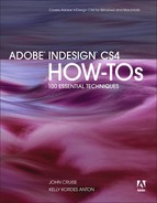
If a layout requires a straight line of any kind, the Line tool offers the easiest way to create it. Select the Line tool, and then click and drag on a page or on the pasteboard (Figure 47a). The point where you click is one end of the line; the point where you release the mouse button is the other end. As you drag, InDesign displays a line between the start point and endpoint and also indicates the line’s midpoint. A live length value is also displayed as you drag. If you hold down the Shift key as you drag, the angle of the line is restricted to increments of 45°. New in InDesign CS4, the Show Transformation Values preference option in the Interface pane of the Preferences dialog box lets you show or hide the live values displayed next to the pointer as you drag.
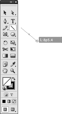
Creating straight lines is a cinch. Creating curvy lines is another matter. One option is to use the Pencil tool, which lets you use the mouse as a pencil; the other option is the Pen tool, which lets you create complex paths but is not particularly easy to use. (See #49 for more about using the Pen tool.) To use the Pencil tool, select it, and then click and drag the mouse as if it were a pencil (Figure 47b). You’ll quickly learn that a mouse is not a very good pencil. If you need more control than the mouse offers, you might want to consider purchasing a graphics tablet.
If you want to create a closed path with the Pencil tool, begin dragging and then hold down Option (Mac OS) or Alt (Windows) as you drag. To close the path, make sure you release the mouse button before you release the Alt or Option key.
After you create a line, use the Selection tool to select and move it or to resize it by dragging a bounding box handle. Use the Direct Selection tool to move either of the endpoints of a straight line or any of the anchor points of a line created with the Pencil tool or the Pen tool.
You can modify lines in many ways. For example, you can assign a stroke weight and line style, and apply a color and tint. You can rotate, shear, and flip lines, and so on. (For more about modifying lines and other objects, see Chapter 7, “Working with Objects.”)
Most page-layout and graphics programs have a drawing tool that’s similar to the Pen tool in InDesign. These tools let you create Bézier curves (also known as vector shapes), which are mathematically defined line segments. Bézier curves can be formed into complex paths that have straight edges, curved edges, or both.
If you’re an Illustrator user or you’ve used Bézier tools in other programs, you’ll be immediately comfortable with InDesign’s Pen tool. If you’ve never used a tool like the Pen tool, it will probably take a little time for you to get the hang of it.
Here’s an easy way to get started with the Pen tool:
1. Select the Pen tool in the Tools panel.
2. Click an empty area of a page or the pasteboard and release the mouse button to establish the first endpoint.
3. Move the Pen pointer, and then click and release the mouse button again to make a segment and another endpoint.
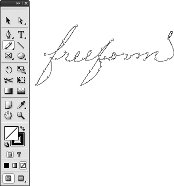
4. To draw additional straight segments, continue moving the pointer, and then clicking and releasing the mouse (Figure 48a).
5. To create an open path with two endpoints, select another tool when you’re done adding segments. To create a closed path, move the pointer back to the first point you made, and then click the mouse when a small white circle is displayed next to the Pen pointer.
Drawing a path that’s made up of curved lines is a little different than drawing straight-edged paths. Instead of clicking and releasing the mouse button when using the Pen tool, click and drag about one-third of the distance to the next anchor point before releasing the mouse.
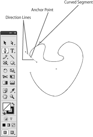
When you click and drag with the Pen tool, InDesign creates an anchor point and a pair of opposing direction lines that form a straight line and meet at the anchor point. A curved segment is drawn to the preceding anchor point (Figure 48b). Continue clicking and dragging to set additional points and form curved segments. Choose a different tool or click the starting point to complete the object.
Figure 48b Click and drag the mouse in the direction of the next anchor point to create curved lines and shapes. This example shows the anchor points along a curved path. The anchor point that ends the path is selected, and you can see the direction lines that are displayed each time you click and drag to create an anchor point and a curved segment.
By combining the click-and-release method for creating straight segments and the click-and-drag method for drawing curved segments, you can use the Pen tool to draw paths that have both straight edges and curved edges.
If you’re not satisfied with the results after using the Pen tool, it’s easy to modify your creation. Use the Direct Selection tool to select and move anchor points and the endpoints of their accompanying direction lines. You can also use the Direct Selection tool to click and drag a segment (a portion of a path between anchor points) of a path. Use the Selection tool to move the object or to resize its bounding box.
The tools grouped with the Pen tool in the Tools panel also let you modify paths:
|
Add Anchor Point tool: Click a path with the Add Anchor Point tool to add an anchor point. |
|
|
Delete Anchor Point tool: Click an anchor point with the Delete Anchor Point tool to remove an anchor point. |
|
|
Convert Direction Point tool: Click a corner anchor point with the Convert Direction Point tool, and then drag to convert it to a smooth anchor point. Or, click a smooth point to collapse its direction lines and convert it to a corner point. |
By default, the Pen tool adds a 1-point stroke and no fill to the paths you create with it. To change the default settings for the Pen tool, modify the settings of the Basic Graphics Frame object style, choose a different object style from the Object Style menu in the Control panel when no objects are selected, or change object attributes such as fill color and tint, stroke weight and style, and so on, when no objects are selected.
The Rectangle, Ellipse, and Polygon tools, and their next-door neighbors, the Rectangle Frame, Ellipse Frame, and Polygon Frame tools, let you create closed shapes that you can use as graphic elements, containers for text and graphics, and paths along which text flows.
The Rectangle, Ellipse, and Polygon tools let you create “unassigned” frames—that is, frames whose content is undefined (neither text nor graphics)—whereas the three frame tools let you create graphics frames into which you can import graphics. (You can tell the difference between an unassigned frame and an empty graphics frame by the X that’s displayed within the graphics frame.) Because it’s easy to change the content of an empty frame, it doesn’t matter whether you use the Rectangle, Ellipse, or Polygon tools or the corresponding frame tools (Rectangle Frame, Ellipse Frame, or Polygon Frame) to create basic shapes.
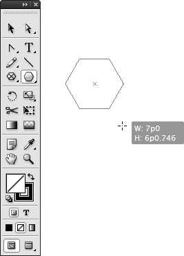
To create a basic shape, select the appropriate tool, and then click and drag (Figure 49).
• The Rectangle and Rectangle Frame tools let you create rectangles and squares. Hold down the Shift key when dragging to create a square.
• The Ellipse and Ellipse Frame tools let you create ellipses and circles. Hold down the Shift key when dragging to create a circle.
• The Polygon and Polygon Frame tools let you create equal-sided polygons and starburst shapes. Hold down the Shift key to create a polygon with equal sides and angles. Press the up arrow key as you drag to add sides to the polygon you’re creating; press the down arrow key to subtract sides. Press the right arrow key as you drag to increase the star inset in 10% increments; press the left arrow key as you drag to decrease the star inset in 10% increments. Press the up and down arrow keys while dragging to continually add or delete points. (Note: When a star inset is specified in the Polygon Settings dialog box, the Polygon and Polygon Frame tools create a starburst shape instead of a regular polygon. Double-click the Polygon tool or Polygon Frame tool to display the Polygon Setting dialog box.)
In addition to the click-and-drag method of drawing basic shapes, you can also click once on a page or on the pasteboard when any of the shape-drawing tools is selected (not the Pen, Pencil, or Line tools). When you click, a dialog box lets you specify the height and width of the shape.
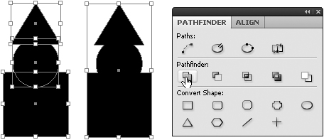
While the Pen tool is the only tool that lets you draw complex shapes, InDesign offers a handy panel that lets you create complex shapes from two or more basic shapes. When multiple objects are selected, the Pathfinder panel (Window > Object & Layout > Pathfinder) provides five options for creating a single shape that’s generated from the selected objects. The results you get from the Pathfinder options depend on the stacking order of the selected objects. If you don’t get the results you want, use the Arrange commands (Object > Arrange) to adjust the stacking order.
Here’s a brief explanation of the Pathfinder options:
|
Add: Combines the selected objects to form a single, all-encompassing shape (Figure 50a). |
|
|
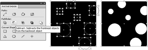
Subtract: All objects in front of the backmost object are removed from (that is, punched out of) the backmost object (Figure 50b). |
|
|
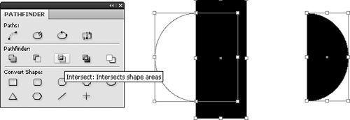
Intersect: Creates a shape from overlapping areas and excludes areas that don’t overlap (Figure 50c). |
|
|
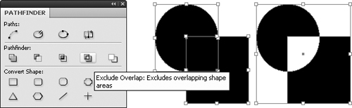
Exclude Overlap: The opposite of Intersect. This option creates a shape from areas that do not overlap (Figure 50d). |
|
|
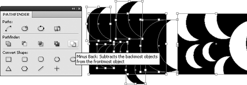
Minus Back: Somewhat like Subtract. All objects in back of the frontmost object are removed from (punched out of) the frontmost object (Figure 50e). |
The five Pathfinder options are also available as commands in the Object menu (Object > Pathfinder).
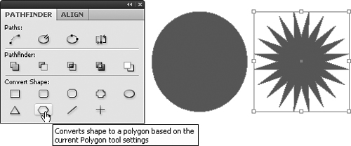
If you need to make minor modifications to an object’s shape, select it with the Direct Selection tool, and then move anchor points, direction points, and segments. For bigger modifications, use the Add Anchor Point, Delete Anchor Point, and Convert Direction Point tools, which are grouped with the Pen tool in the Tools panel. To convert an object into one of nine predefined shapes, use the Pathfinder panel (Window > Object & Layout > Pathfinder).
To change an object’s shape with the Pathfinder panel, select the object, and then click one of the nine Convert Shape buttons in the panel (Figure 51):
|
Rectangle |
|
|
Rounded Corner Rectangle |
|
|
Beveled Corner Rectangle |
|
|
Inverse Rounded Corner Rectangle |
|
|
Ellipse |
|
|
Triangle |
|
|
Polygon |
|
|
Line |
|
|
Vertical/Horizontal Line |
You’ll find four additional buttons for changing the shape of objects at the top of the Pathfinder panel. The same four options are also available in the Object menu (Object > Paths):
|
Join Path button: When an open path is selected, clicking the Join Path button connects the two endpoints of the path to create a closed shape. When two open paths are selected, clicking the Join Path button connects an endpoint from each path to create a single open path. |
|
|
Open Path button: The Open Path button creates an open shape from a closed shape, much like using the Scissors tool on a closed path. InDesign chooses an anchor point at which the path is opened. You may need to select the object with the Direct Selection tool to determine where the object has been split. |
|
|
Close Path button: The Close Path button creates a closed path from an open path by connecting the two endpoints. |
|
|
Reverse Path button: If you’ve created a shape with one or more “holes” in it—for example, a doughnut shape created by using the Subtract button on a pair of concentric circles—selecting the inner path and then clicking the Reverse Path button in the Pathfinder panel will eliminate the hole while keeping the path. Clicking the Reverse Path button again will show the hole. |