In this chapter, we're going to look at these topics:
Collisions between rectangles
Collisions between rectangles and circles
Collisions between rectangles, circles, and triangles
We'll then take a detailed look at two important case studies that use all the techniques we've covered in this book so far, along with a few new ones. We'll begin with an introduction to the technique that lets us do efficient polygon collision detection.
Note
This chapter assumes that you're fluent in the vector math concepts covered in Chapters 2 and 3. If you think you're a little hazy on any vector math topics, review those earlier chapters, and work through the concepts and code in your own projects. There's no need to rush into this chapter until you're fully confident you understand the previous material.
At the end of Chapter 2, I explained how you can make polygons by joining a series of lines. Checking for a collision with the polygon then just becomes a question of checking for collisions with all of the lines. So if you're testing for a collision between a particle and a hexagon, for example, your code checks whether the particle is intersecting with any of the hexagon's six lines that make up its sides. This works, and for many scenarios, it may be all you need. But its one big drawback is that it checks for collisions that have no likelihood of ever occurring.
Imagine that you have 100 hexagons on the stage, and one particle that could collide with any of them. You know that your particle is only ever going to collide with one side of one hexagon. If you check each side of every hexagon on the stage, you'll be doing 599 more collision checks than necessary. This eats a huge hole in your game's performance budget. It's as if you spent $1 on a slice of pizza, but unwittingly dropped $599 on the floor of the pizza parlor while digging through your pockets for your change. Multiply that by 30 or 60 times per second, and you have a real problem! This is what programmers refer to with the technical term expensive, and I'm sure you will agree with them.
Doing collision detection wisely means doing collision tests only between objects that are likely to collide. If you're checking for collisions between a particle and those 100 hexagons, you should consider that of those 100 hexagons, the particle is only ever going to collide with hexagons that it can reach within one frame of movement. That means just those hexagons that are within range of its velocity vector—perhaps only three or four of them. If you can find those few hexagons, you've immediately saved 96% of your performance budget! This applies not only to polygons, like squares and hexagons, but also to circles and particles.
Checking for collisions with objects that are in the immediate vicinity of each other is called broad-phase collision detection. The simplest way of doing a broad-phase collision check is to overlay a grid onto the stage and compare only those objects that are in directly adjacent cells in the grid. It requires quite a bit of computing overhead to manage a broad-phase collision system, so the performance benefit is usually apparent only if you're testing for collisions between more than a few hundred objects each frame.
Once you've found the most likely hexagon to collide with, you need to determine which side of the hexagon the particle is hitting. Checking all six sides arbitrarily is very inefficient, so you need to narrow down the search to the most likely sides. This step in the process, where you test for collisions between individual objects, is called narrow-phase collision detection.
The broad-phase step of this process is covered in Chapter 8. In this chapter, we'll work with one of the most widely used and efficient techniques for doing narrow-phase collision detection with polygons: the separating axis theorem (SAT).
The SAT is an observation about how polygons intersect. It's widely regarded as the most efficient way to check whether polygons are colliding. It's also pretty easy to understand:
If there is an axis on which any two objects don't overlap, then there's no collision between the objects. In the case of two rectangles, this means that if the rectangles overlap on the x axis but not the y axis, then they're not colliding. The axis on which they don't intersect is the separating axis that gives the theorem its name.
If the objects overlap on all their axes (both x and y), then a collision has occurred.
The axis with the smallest amount of overlap is the axis on which the collision is occurring.
Note
The SAT was first formulated by legendary computer scientist and software engineer Stefan Gottschalk. It caught the eye of the Flash game design world in an online tutorial by Metanet, makers of the highly respected Flash and PlayStation game N.
In any game, the chance that two objects are not colliding is far more likely than that they are colliding. The SAT capitalizes on this fact. It's very efficient because you can find out immediately whether two objects are overlapping just by testing one axis. If there's no overlap on that one axis, you have your answer: there's no collision. It's a quick escape, and you've just saved yourself some processing power. You don't need to bother testing any of the other axes.
In the case of rectangles, this means you can reduce collision checks by up to half. In the case of a complex polygon, like a hexagon, it means needing to do up to three times fewer collision checks.
However, if you find that two objects are overlapping on one axis, it doesn't mean that the objects are actually colliding. It means that they could be, but you don't know yet. So, you next need to check another axis to be sure. In the case of rectangles, if you find an overlap on both the x and y axes, then the rectangles are definitely overlapping and you have a collision. If you find any axis without an overlap, then there's no collision, and you can stop further checking.
Anyway, that's the theory. If this all sounds a bit too abstract, let's take a step back and look at a practical example.
The simplest polygon collision detection you do is between two squares or two rectangles. Imagine that you need to check for a collision between two squares on the stage. In pseudo code, a basic SAT algorithm for squares looks like this:
if(the squares overlap on the x axis)
{
  //There might be a collision! Let's check:
  if(the squares overlap on the y axis)
  {
//The squares overlap on both axes, so there's definitely a collision
//The collision is occurring on the axis with the smallest amount of
overlap
}
else
{
//There's no overlap on the y axis, so there's no collision
}
}
else
{
//There's no overlap on the x axis, so there's no collision
}What do I mean by "if the squares overlap on the x or y axis"?
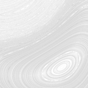
Take a look at Figure 4-1, which depicts two squares on the stage. They're obviously not intersecting, which we can plainly see with our eyes. But we need to find a way to describe this in programming code so that our games can also see it.
You can see from Figure 4-1 that those two squares exist on a stage with an x axis and a y axis. Conveniently enough, the sides of the squares are also aligned to the stage's x and y axes:
Their top and bottom sides are parallel to the x axis.
Their left and right sides are parallel to the y axis.
Note
In technical collision detection literature, squares or rectangles whose sides are aligned to the x and y axes are called axis-aligned bounding boxes, or AABBs. In other words, the stage is rectangular and the squares are rectangular. Nothing is rotated. This is the simplest collision scenario you can have. Game designers will often wrap odd-shaped, nonrectangular objects in AABBs because using them for collision detection is extremely fast.
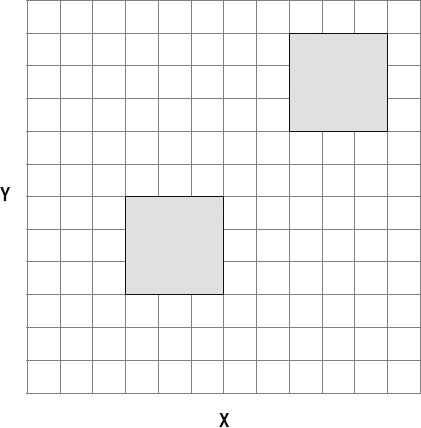
To check whether the squares are intersecting, we don't need to check all four sides of each square against all four sides of the other square. We just need to check whether the sides of the squares are intersecting on the two axes. To do this, we need to use projection. We must project each square onto the x and y axes. You'll recall from Chapter 2 that the projection of a shape is the shadow that it casts if you were standing behind it shining a light. In this case, each square needs to cast two shadows: one shadow onto the x axis and another onto the y axis. Figure 4-2 illustrates this.
How can we use these projections to find out whether the squares are intersecting?
The SAT says that if the projections of the shapes don't overlap on any axes, then the shapes don't overlap. Bingo! That pretty much sums up Figure 4-2. You can clearly see that the projections don't overlap at all.
How will our SAT pseudo code handle this "no collision" condition? First, it will check for any overlaps on the x axis. It finds none, so it knows that there is no collision. It can skip a whole block of code and jump straight to the end. The code in bold indicates the code that's being triggered.
if(the squares overlap on the x axis) //They don't
{
  //There might be a collision! Let's check:
  if(the squares overlap on the y axis)
  {
    //The squares overlap in both axes, so
    //there's definitely a collision. The collision is occurring on
    //the axis with the smallest amount of overlap
  }
    else
    {
    //There's no overlap on the y axis, so there's no collision
    }
}
else
{
//There's no overlap on the x axis, so there's no collision
}
This is why using the SAT is so efficient: it doesn't do any extra checking.
So what happens if the squares overlap on the x axis? Let's find out.
In Figure 4-3, you can see that the top square has moved to the left. The projections of both squares are now overlapping on the x axis.
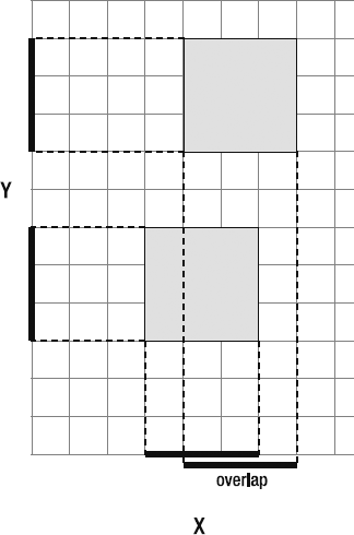
Of course, you can see that even though they overlap on the x axis, the squares still don't intersect. Let's see if our SAT pseudo code agrees with us.
if(the squares overlap on the x axis) //They do{//There might be a collision! Let's check:if(the squares overlap on the y axis) //They don't{ //The squares overlap in both axes, so //there's definitely a collision. The collision is occurring on //the axis with the smallest amount of overlap } else {//There's no overlap on the y axis, so there's no collision} }
else
{
  //There's no overlap on the x axis, so there's no collision
}Yes, it does agree with us! It detects the overlap on the x axis, and then goes on to check for an overlap on the y axis. It doesn't find any, so it correctly determines that there's no collision.
Now let's push the example further and see what happens when the squares overlap on the y axis as well. As you can see in Figure 4-4, the shapes are now clearly intersecting.
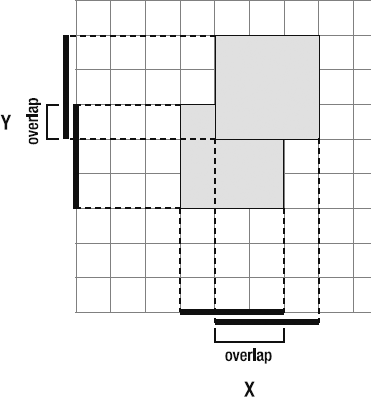
Figure 4.4. The squares overlap on both axes, so we have a collision. The collision occurs on the y axis, which has the smallest amount of overlap.
What will the SAT have to say about this?
if(the squares overlap on the x axis) //They do{//There might be a collision! Let's check:if(the squares overlap on the y axis) //They do{//The squares overlap in both axes, so//there's definitely a collision. The collision is occurring on//the axis with the smallest amount of overlap}
else
{
//There's no overlap on the y axis, so there's no collision
}
}
else
{
  //There's no overlap on the x axis, so there's no collision
}Not only does it detect the collision, but it also knows that the collision is happening on the y axis, which is the axis with the smallest amount of overlap.
This, in a nutshell, is the SAT.
Before continuing, you need to be aware of a fundamental problem of the SAT system that could give you unexpected results if your game objects move too far in one frame. If objects are moving very quickly, the axis with the smallest amount of overlap might not be the one on which the collision is occurring.
For example, look at Figure 4-4 and imagine that the upper square is moving at a high velocity, from the right side of the stage to the left, and that it has collided with the lower square from the right. Imagine that it was moving so fast that it managed to penetrate more than halfway into the lower square. Our eyes would tell us that the collision is happening on the x axis, which is correct. But the SAT would notice that the overlap is less on the y axis, and tell us that the collision happened from above. If we used this information to resolve the collision in a game, the upper square would appear to be unnaturally pushed up above the lower square.
This is an unavoidable aspect of the SAT algorithm, so you'll need to decide whether this is something you can live with. The speed and efficiency of the SAT is usually enough compensation, but if your game demands greater precision, here are some work-arounds to help you live with it:
Limit you game engine so that it's never possible for the velocities of any objects to be greater than the half width of the smallest object.
Even if the axis information is not what you want, you can still use the SAT to tell you whether a collision is occurring. Just don't use its overlap values to resolve the collision. Instead, resolve the collision in another way:
Use the line-versus-point collision techniques from Chapter 2 to resolve the collision.
If you know the direction of the collision, and you know where the collision boundary is, use that boundary to resolve the collision. In Chapters 8 and 9, we'll look at some efficient ways of resolving collisions that you can use if you set up your game world with fixed collision boundaries.
SAT detects collisions very efficiently, and that alone is a good enough reason to use it. But you'll need to decide whether the information it tells you about the direction of the collision is useful or correct in the context of your game.
So far, so good, but there are a few more details we need to figure out before we have a complete working system. We're going to look at how to project the shapes onto each axis in detail in the pages ahead, as this varies in complexity depending on the kinds of polygons you're using. Here, I'll show you how to determine whether the projections are overlapping, and how to calculate the amount of overlap.
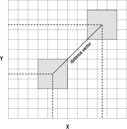
We need a vector that runs between the centers of both squares. This is the distance vector. The distance vector also needs to be projected onto each axis, as shown in Figure 4-5.
Use the distance vector's projections like a measuring stick to measure the distance between the centers of the projections of the squares on each axis, as illustrated in Figure 4-6.
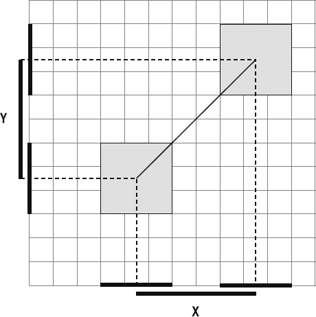
Figure 4.6. Measure the distance between the projections of the shapes to find out whether they overlap.
Follow these steps to find out whether there's any overlap:
Add the projections of the shapes together, and divide that number in half. In Figure 4-5, the total of the projections of the squares on the x axis is 6. Half of 6 is 3.
If the magnitude of the projected distance vector is less than the value in step 1 (in other words, if it's less than 3), then the shapes overlap on that axis.
The amount of overlap between the shapes is the difference between the value from step 1 and the projected distance vector's magnitude.
It's much easier to see in pictures than it is to read, so take a good look at Figure 4-7. (The convention I'm using in this book is that variable names that start with p refer to projection vectors.)
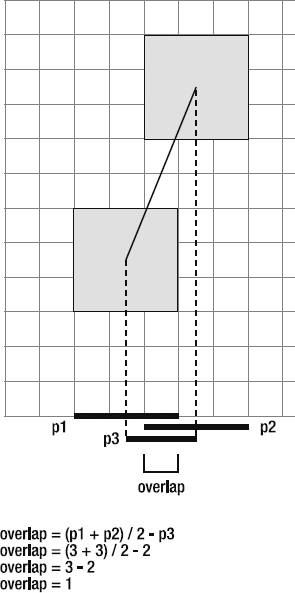
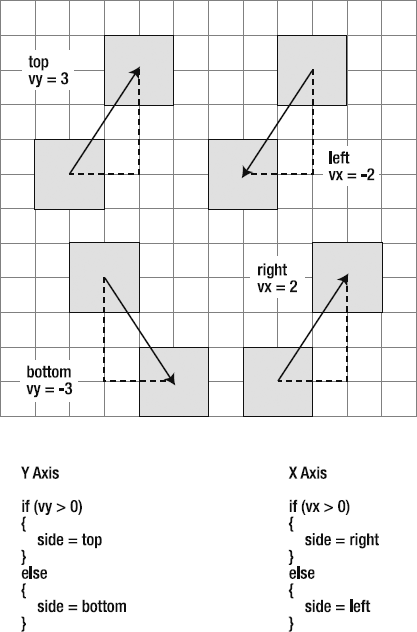
Now that we know on which axis the collision is happening, we need to find out on which side of the square it's taking place. This is easy to figure out by checking whether the distance vector's vx and vy are greater or less than zero.
If the collision is happening on the x axis, is it happening on the right or left side of the square? Find the distance vector's
vx. If it's greater than zero, then the collision is happening on the right. If it's less than zero, the collision happens on the left.If the collision is happening on the y axis, is it happening on the top or bottom side of the square? Find the distance vector's
vy. If it's greater than zero, the collision is happening on the top. If it's less than zero, the collision happens on the bottom.
Figure 4-8 shows how to find the collision side. It may look a bit confusing at first so take a moment for the logic to sink in.
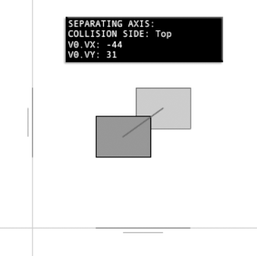
You can find a working example of this entire system in the chapter's source files in the SeparatingAxis folder. The example looks like Figure 4-9 when you run it. Strangely, I'm going to recommend that you not look the source code yet. The source code has been written to exactly match the concepts we've covered so far, so the SeparatingAxis SWF is really just an interactive illustration of these concepts. But if you're just working with rectangles, there are shortcuts you can take that can greatly simplify your code. In the next section, we'll address the specifics of using the SAT with rectangles.
I've shown you the general fundamentals of a SAT-based collision system. It's the basic theory, and applies to all shapes, no matter how complex.
As you've seen, collisions between squares and rectangles with the SAT are very easy to understand. If you start using the SAT with complex irregular shapes and find yourself getting confused, just come back to these pages to remind yourself of the process and review the examples. If you understand the SAT with squares, you can apply those same principles to all polygons. Just take it slowly, and apply each principle step by step.
Collision detection with squares or rectangles that are aligned to the stage's x and y axes is the simplest implementation of the SAT. In fact, it's even simpler than my description of it in the previous section. There are three important reasons why:
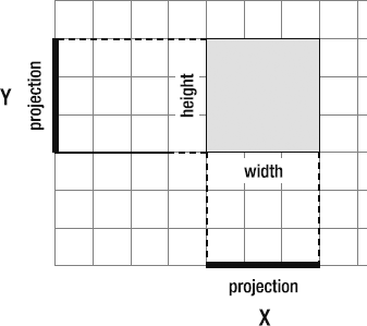
If a rectangle is aligned to the stage's x and y axes, you don't need to do any projection. A rectangle's projection on the x axis is the same as its width, and its projection on the y axis is the same as its height, as illustrated in Figure 4-10. That means you just need to use the height and width values.
The distance vector's
vxandvyare the same as its projections on the x and y axes, as shown in Figure 4-11.You can greatly simplify your calculations if you use half-width and half-height values. This is true not only for rectangles, but also for all polygons, no matter their orientation. (If you need to project a polygon's side onto an axis, divide the projection in half.) You'll see how in the examples ahead.
The short story is that because of all these shortcuts, applying the SAT with rectangles requires only some very basic vector math. It's something every game designer should know, and I'll walk you through each step of the way.
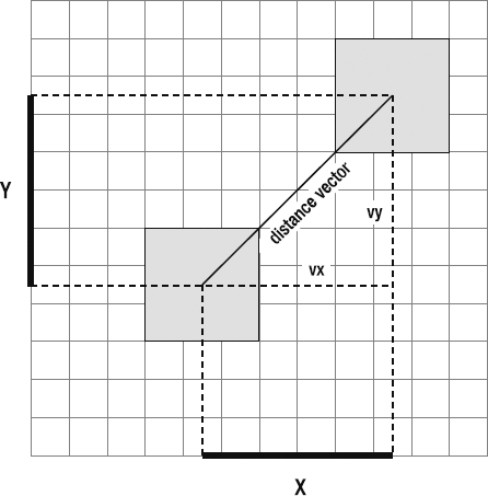
Figure 4.11. You don't need to project the distance vector, because its vx and vy are the same as its projections.
Run the SWF file RectangleVsRectangle in the chapter's source files. Use the mouse or arrow keys and move the left rectangle into the right one. It hits it and bounces away at the correct angle. Graphs show you the rectangles' total half widths and half heights, and how they compare to the distance vector's vx and vy.
In Figure 4-12, you can see that the distance vector's vy is less than the total half widths. This indicates that the rectangles are overlapping on the y axis. When they overlap on both axes, a collision is detected.
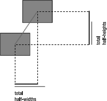
From the SWF and Figure 4-12, it should be quite how clear how the collision is found.
This example also uses bounce and friction. When you run the SWF, the bounce effect is evident, but what may not be that obvious is the surface friction. The player's rectangle can slide against the surface of the stationary rectangle, and the exact slipperiness of that surface is the direct result of the friction calculation. You'll be glad to know that bounce and friction are calculated in exactly the same way that we calculated them in the previous two chapters, so there's nothing new to learn. The implementation is just slightly different, as I'll explain in the pages ahead.
Take a look at the source file, and you'll see that the rectangles are made using RectangleModel and RectangleView objects. These are the same as the CircleModel and CircleView objects we used in the previous chapter, except that they create rectangles. RectangleModel and RectangleView also extend the abstract AVerletModel and AVerletView classes, so the underlying code is the same as we've been using for circles.
The most important section of the code is the enterFrameHandler, and I'll list it here so that you can see how it works in context. These are the names of the important objects that are used:
_r1is theRectangleModelthat serves as the player's rectangle. This is the rectangle you can move with the mouse and keyboard._r2is the stationary rectangle._v0is the distance vector between the rectangles.
Follow the comments through the code to see how the collision is detected and resolved. Bounce and friction are handled by the bounceOnPlane method, and we'll look at how that works next.
private function enterFrameHandler(event:Event):void
{
  //Update _r1 (player's rectangle)
  _r1.update();
  StageBoundaries.bounce(_r1, stage);

  //Update _r2
  _r2.update();
  StageBoundaries.bounce(_r2, stage);
  //Vector between rectangles
  _v0.update(_r1.xPos, _r1.yPos, _r2.xPos, _r2.yPos);

  //Check whether the projection on the
  //x axis (in this case the v0's vx)
  //is less than the combined half widths
  if(Math.abs(_v0.vx) < _r1.width * 0.5 + _r2.width * 0.5)
  {
    //A collision might be occurring! Check the other
    //projection on the y axis (v0's vy)
    if(Math.abs(_v0.vy) < _r1.height * 0.5 + _r2.height * 0.5)
    {
      //A collision has occurred! This is good!

      //Find out the size of the overlap on both the x and y axes
      var overlap_X:Number
        = _r1.width * 0.5
        + _r2.width * 0.5
        - Math.abs(_v0.vx);

      var overlap_Y:Number
        = _r1.height * 0.5
        + _r2.height * 0.5
        - Math.abs(_v0.vy);

      //The collision has occurred on the axis with the
      //*smallest* amount of overlap. Let's figure out which
      //axis that is

      if(overlap_X >=  overlap_Y)
      {
        //The collision is happening on the x axis
        //But on which side? _v0's vy can tell us
        if(_v0.vy > 0)
        {
          _collisionSide = "Top";
//Move the rectangle out of the collision_r1.setY = _r1.yPos - overlap_Y; } else { _collisionSide = "Bottom";//Move the rectangle out of the collision_r1.setY = _r1.yPos + overlap_Y; }//The rectangle needs a vector to bounce against.//Plot the x axis at r1's positionvar xAxis:VectorModel = new VectorModel ( _r1.xPos - _r2.width * 0.5, _r1.yPos, _r1.xPos + _r2.height * 0.5, _r1.yPos );//Bounce the rectangle using the bounceOnPlane methodbounceOnPlane(_r1, xAxis, 0.1, 0.98); } else {//The collision is happening on the y axis//But on which side? _v0's vx can tell usif(_v0.vx > 0) { _collisionSide = "Left";//Move the rectangle out of the collision_r1.setX = _r1.xPos - overlap_X; } else { _collisionSide = "Right";//Move the rectangle out of the collision_r1.setX = _r1.xPos + overlap_X; }
//The rectangle needs a vector to bounce against//Plot the y axis at r1's positionvar yAxis:VectorModel = new VectorModel ( _r1.xPos, _r1.yPos - _r2.height * 0.5, _r1.xPos, _r1.yPos + _r2.height * 0.5 );//Bounce the rectangle using the bounceOnPlane methodbounceOnPlane(_r1, yAxis, 0.1, 0.98); } } else { _collisionSide = "No collision"; } } else { _collisionSide = "No collision"; } //...Display graphs and update the status box... }
When the squares collide, they need a surface to collide against so that the code can calculate bounce and friction. This "surface" is just a vector that describes the axis on which the collision happens. This vector doesn't actually need to be visible on the stage, and can be calculated just when it's needed.
When the squares collide on the y axis, a vector is created that describes that axis:
var yAxis:VectorModel
  = new VectorModel
  (
    _r1.xPos,
    _r1.yPos - _r2.height * 0.5,
    _r1.xPos,
    _r1.yPos + _r2.height * 0.5
  );
It's not visible on the stage, but Figure 4-13 shows what it would look like if you could actually see it.
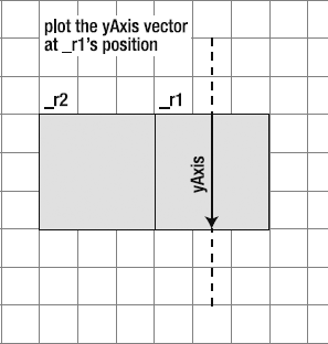
Figure 4.13. Create an imaginary vector that descibes the axis that the collision is happening on. It's needed to calculate bounce and friction.
This is the same kind of "imaginary surface" that we created in Chapter 3 to bounce two circles together. It's just used to give the bounce and friction calculations some accurate numbers.
We can now take this vector and send it to the bounceOnPlane method, along with the name of the rectangle and the bounce and friction values.
bounceOnPlane(_r1, yAxis, 0.1, 0.98);
The bounceOnPlane method is a general method that can accept any objects that extend the AVerletModel class. This includes RectangleModel objects.
public function bounceOnPlane
  (
    verletModel:AVerletModel,
    plane:VectorModel,
    bounce:Number,
    friction:Number
  ):void
{
  //The model's movement vector
  var v1:VectorModel
    = new VectorModel
    (
      verletModel.xPos,
      verletModel.yPos,
      verletModel.xPos + verletModel.vx,
      verletModel.yPos + verletModel.vy
    );
//Find the projection vectorsvar p1:VectorModel = VectorMath.project(v1, plane); var p2:VectorModel = VectorMath.project(v1, plane.ln);//Calculate the bounce vectorvar bounce_Vx:Number = p2.vx * −1; var bounce_Vy:Number = p2.vy * −1;//Calculate the friction vectorvar friction_Vx:Number = p1.vx; var friction_Vy:Number = p1.vy; verletModel.vx = (bounce_Vx * bounce) + (friction_Vx * friction); verletModel.vy = (bounce_Vy * bounce) + (friction_Vy * friction); }
v1 is the rectangle's movement vector, and, as you can see, it's calculated when only it's needed. (The bounceOnPlane method is also available in the VectorMath class in the com.friendsofed.vector package.)
This is the same formula that we've been using to calculate bounce and friction in Chapters 2 and 3, so make sure you review those sections for more details on how this works.
Finding the separating axis for rectangles is easy because you have only two axes to worry about. And because those axes are aligned to the stage axes, you don't need to do any projection. Things get a bit more complicated when you start using polygons that have angles that aren't at 90 degrees
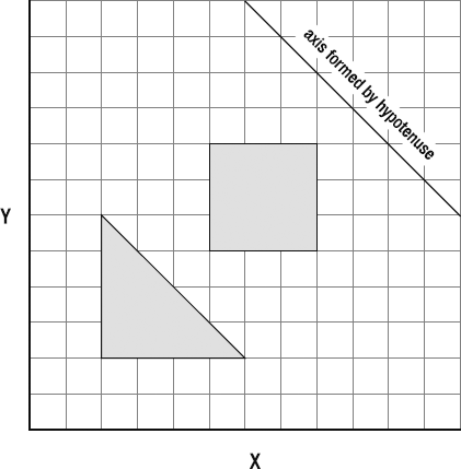
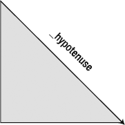
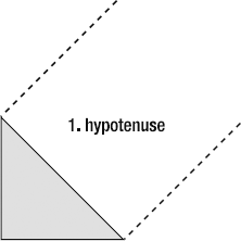
Triangles are a good next step, because in addition to x and y axes, they have an additional axis: the hypotenuse, which is the triangle's slope, as shown in Figure 4-14. (In this chapter, all the examples involve right-angled triangles, which are formed by a 90-degree angle.)
Our job is to figure out a way to find out if another polygon is intersecting the hypotenuse. The SAT can help us, but the solution won't be obvious right away.

Note
I'm going to issue an unusual warning about the next few sections. You will need to be very comfortable with the SAT and projecting vectors to fully appreciate the code and examples. If you find it a bit overwhelming, don't panic! Take a few steps back and make sure that you fully understand the SAT with rectangles and can write your own rectangle-versus-rectangle collision code. That's very important, and forms a core game-design technique. Only continue when you feel comfortable with the code and the concepts for rectangle collisions.
You'll be pleased to know that SAT collisions with triangles and other nonrectangular polygons are not essential game-design techniques. You can have a flourishing game-design career without ever needing to develop the collision code from scratch yourself. APIs like the open source Box2D contain libraries of code that do all of this math for you, and probably much more efficiently than you could if you were writing the code yourself from scratch. If you are reading this section and thinking, "This is just too technical!" don't worry. Box2D and other physics libraries will handle it for you.
However, even if you don't implement any of this code yourself, I do think it's a good idea to get some general familiarity with the concepts and problems you'll need to think about. You never know when it might be useful. It's also an important step to writing your own game physics engine, which some of you may want to do. But if it's just too much for now, jump ahead to the Block Game case study at the end of the chapter. You won't miss any crucial information by skipping the next few sections.
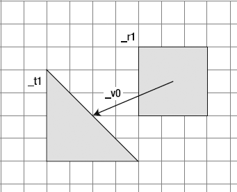
Let's take a look at the problem that we need to solve. How can we find out whether the triangle and square are intersecting?
Figure 4-15 shows all the axes formed by a triangle and a square: the x axis, the y axis, and the hypotenuse, which is a new, third axis.
As you've seen from the examples involving rectangles, we now know how to check for an intersection on the x and y axes. But we don't know how to check for an intersection on the hypotenuse. Somehow we need to find a way to figure out if the square is intersecting this new third axis.
To solve this problem with the SAT, we need to first project each shape onto each axis. This is the first, most basic step in any SAT system. Figure 4-16 shows what this will look like.
You can see that each shape is casting a shadow of itself on each axis. Each of these shadows is a projection vector that you can calculate using the techniques described in Chapters 2 and 3.
But take a close look at Figure 4-16—isn't something wrong there?
This is what we know so far about the SAT: if the projections of the shapes overlap on all axes, then the shapes overlap. In Figure 4-16, all the projections of both the shapes do overlap. According to the SAT, shouldn't that mean that the shapes are intersecting? However, you can clearly see that the shapes themselves are not intersecting. What's going on here?
This exposes a deep truth to the SAT, and one which is often confusing for game developers just coming to grips with using it for the first time.
Don't project the shapes on to the axis; project them onto the axis's normal.
It's worth cutting that phrase out of this book and taping it to your computer monitor, because forgetting this is one of the big reasons the SAT can be confusing to implement successfully.
Here's what we need to do:
Find the normal of the triangle's hypotenuse.
Project both shapes onto the hypotenuse's normal.
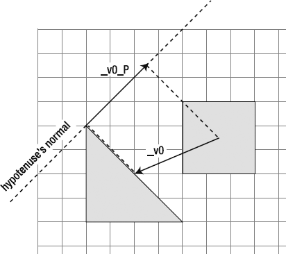
Figure 4-17 illustrates this.
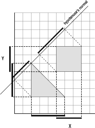
The distance between the square and the triangle will be the same as the distance between their projections on the hypotenuse's normal, as shown in Figure 4-18.
You can see in Figure 4-19 that when the shapes are overlapping, they overlap on all three axes.
All we need to do next is measure the amount of overlap, and we'll know how much to separate the shapes after they collide. Thanks to the SAT, we also know that the square is overlapping on the hypotenuse because it's the axis on which the overlap is the smallest. Very cool!
But this brings up a big question: When we were using the SAT with rectangles, we didn't need to project onto the normals of the x and y axes. Why not?
Because, very simply, the x axis is the normal of the y axis, and vice versa. Remember that a normal is just a vector that's at 90 degrees to the main vector. So actually we were projecting on the axis normals, but we didn't need to think of them in that way. This is another very beneficial shortcut to using rectangles. But whenever you have a polygon, like a triangle, that has an axis that isn't at 90 degrees, you must remember to project the shapes onto that axis's normal.
We've got the theory down, now our next job is translate it into usable code.
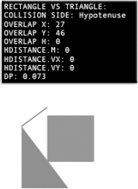
You can find a working example of this system in the RectangleVsTriangle folder. Run the SWF, and you'll see that the collision detection between the rectangle and triangle works just as you would expect, as shown in Figure 4-20. A red line represents the projection of the square onto the hypotenuse. (It's actually half of the square's projection. Why only half the projection is used is explained soon.) Bounce and friction are created with the same bounceOnPlane method that we used in the previous example.
Rather than deluge you with source code, I'll take you step by step through the code that makes this work. In the diagrams that follow, I've given all the vectors and shapes the same names as in the source code. I'll highlight the important bits from the source code that match the diagrams, so you can use this as a map to understanding how the code works. Or better yet, use it a basis for writing your own code. Writing your own code is always the best way to learn.
The first step is to make the shapes. _r1 is the RectangleModel. t1 is the TriangleModel. You'll find the TriangleModel and TriangleView classes in the com.friendsofed. gameElements.primitives package. They follow the same format as the classes we used for circle and rectangle objects. The one difference is that you assign the triangle's inclination. This is a string that can be "right" or "left" depending on which way you want the triangle's hypotenuse to face.
This code produces a triangle that faces toward the left:
private var _t1:TriangleModel = new TriangleModel(60, 80, "left");
Its default value is "right".
Step 2 is to plot the hypotenuse as a vector. The triangle's hypotenuse is a VectorModel object, just like any other VectorModel object that we've used so far. We need to determine where it starts and ends so that we can figure out how to project the shapes onto its normal, as shown in Figure 4-21.
private var _hypotenuse:VectorModel = new VectorModel();

_hypotenuse.update
  (
    _t1.xPos - _t1.width * 0.5,
    _t1.yPos - _t1.height * 0.5,
    _t1.xPos - _t1.width * 0.5 +  _t1.width,
    _t1.yPos - _t1.height * 0.5 + _t1.height
  );
I've calculated it like this in the source code so that the process is as clear as possible. However, TriangleModel objects also allow you to access the hypotenuse as a built-in property. The hypotenuse is worked out for you automatically when you create a TriangleModel object, and you can access it like this:
_t1.hypotenuse
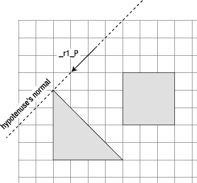
Step 3 is to create a distance vector between the center of the rectangle and the center of the triangle. Figure 4-22 illustrates this step.
private var _v0:VectorModel = new VectorModel();
_v0.update(_r1.xPos, _r1.yPos, _t1.xPos, _t1.yPos);
The triangle's "center" is measured from its top-left corner by adding half its height and half its width.
Step 4 is to project the distance vector onto the hypotenuse's normal. Position the projection so that it starts at point A of the hypotenuse's left normal and extends as far as the projection's vx and vy. Figure 4-23 illustrates this step.
var v0_P:VectorModel = VectorMath.project(_v0, _hypotenuse.ln)
_v0_P.update
  (
    _hypotenuse.ln.a.x,
    _hypotenuse.ln.a.y,
    _hypotenuse.ln.a.x - v0_P.vx,
    _hypotenuse.ln.a.y - v0_P.vy
   );
Any time you see an uppercase P in the code, it refers to the projected version of the vector.
Step 5 is to project the square onto the hypotenuse's normal. Imagine that that there's a light behind the square that's casting a shadow on the normal, as shown in Figure 4-24.

Projecting an entire shape onto a line is a new technique that we haven't looked at yet. You've seen how to project individual vectors onto other vectors, but now we need to project a two-dimensional shape onto a one-dimensional line. How can we do that?
If that shape is a rectangle, there are two ways: the long way and the shortcut. The RectangleVsTriangle source code uses the long way, because it's more flexible and you'll need to learn how to do it if you project polygons that are more complex than rectangles. But let's look at the shortcut first, because it's easy to do and you'll find many good opportunities to use it in your game projects.
Extend a vector from the bottom-left corner of the square to the top-right corner. You can then project that new vector onto the hypotenuse, as shown in Figure 4-25. If you're using squares or rectangles, this will save you a few extra calculations.
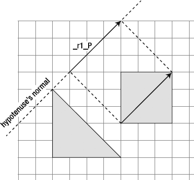
Figure 4.25. The shortcut: create a diagonal vector through the square and project it onto the hypotenuse's normal.
The long way is more flexible because it will work with shapes whose sides don't form right angles:
Plot each side of the shape as a vector.
Individually project each side onto the hypotenuse.
Figure 4-26 illustrates this approach.
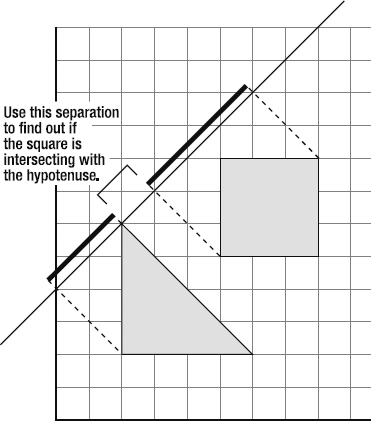
Remember that the whole point of doing all this is to figure out how big the gap is between the hypotenuse and the projection of the square. We're not quite there yet, but we have all the pieces of the puzzle and are just about ready to solve it.
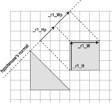
It turns out that we can vastly simplify this problem if, instead of projecting the square's width and height, we project its half width and half height, as shown in Figure 4-27. This reduces the number of calculations we need to do by almost four times. This is because if we combine half of the square's width and height projections, and then subtract the projection of the distance vector, the result will tell us exactly how much space is in the gap between the square and the hypotenuse.
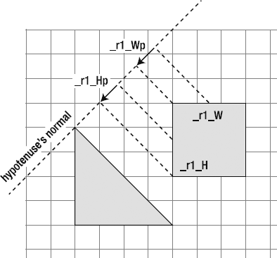
Next, add those projections together to create a new vector, as shown in Figure 4-28. You can see this new vector as the red moving line in the RectangleVsTriangle SWF.
Finally, if you subtract this new vector from the projection of the distance vector, you can find the gap, as shown in Figure 4-29. It doesn't matter which direction this vector points toward.
Here's the code that finds and projects the square's half height and half width onto the hypotenuse's normal:
var r1_W:VectorModel = new VectorModel(0,0,0,0, _r1.width / 2, 0);
var r1_Wp:VectorModel = VectorMath.project(r1_W, _hypotenuse.ln);
var r1_H:VectorModel = new VectorModel(0,0,0,0, 0, _r1.height / 2);
var r1_Hp:VectorModel = VectorMath.project(r1_H, _hypotenuse.ln);

_r1_P.update
  (
    _hypotenuse.ln.a.x + _v0_P.vx,
    _hypotenuse.ln.a.y + _v0_P.vy,
    _hypotenuse.ln.a.x + _v0_P.vx - (r1_Wp.vx - r1_Hp.vx),
    _hypotenuse.ln.a.y + _v0_P.vy - (r1_Wp.vy - r1_Hp.vy)
  );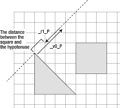
Figure 4.29. The distance between the square and the hypotenuse is equal to the projection of the distance vector minus the projection of the shape's half width and half height.
Note
After I wrote this code, I stared at it for a moment and thought, "Wow, what a big mess of code!" It looks pretty intricate, and it is. But, if you step through it slowly, you'll see that it just uses basic math to describe what you can see visually in Figure 4-29. While I was writing this, I wasn't actually thinking about the code at all. My head was just full of little diagrams of vectors, and the code that resulted seemed to just happen incidentally.
You'll find it easy to write your own code like this if you forget about the numbers for a while and just think about the pictures. It all amounts to nothing more than projecting, adding, and subtracting vectors—and you've been doing that for at least 100 pages already!
You'll also find that it's much easier to write code like this yourself from scratch than it is to look at someone else's code (like mine) and work backward to try to understand it. As I've been encouraging you to do all along, use these concepts and write your own code. That's by far the best way to learn and internalize all these concepts. Maybe even the only way.
Step 6 is to create a vector to represent the gap between the square and the hypotenuse, as shown in Figure 4-30. If you create a vector to represent it, you'll have a few more numbers you can play with. In the source code, this vector is called hDistance because it represents the distance between the square and the hypotenuse.
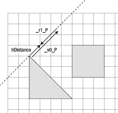
var hDistance:VectorModel
  = new VectorModel
  (
    _hypotenuse.ln.a.x,
    _hypotenuse.ln.a.y,
    _hypotenuse.ln.a.x - _v0_P.vx - _r1_P.vx,
    _hypotenuse.ln.a.y - _v0_P.vy - _r1_P.vy
);Step 7 is to find the dot product between the hDistance and the hypotenuse's left normal. This is the last number that we need. It will help us to check whether the two shapes are overlapping.
var dp:Number = VectorMath.dotProduct(hDistance, _hypotenuse.ln);
Step 8 is to Check each axis to find out if the shapes are overlapping. We have three axes to check. We know from the SAT algorithm that if there's an overlap on all three axes, then the shapes themselves are overlapping.
This is what the logic for this looks like in pseudo code:
if(there's an overlap on the x axis)
{
  //There might be a collision, but we don't yet know.
  //Let's check the y axis:

  if(there's an overlap on the y axis)
  {
    //We're getting closer, but we need to check one more axis to be sure

    if(there's an overlap on the hypotenuse)
    {
      //A collision has occurred!
      //Find the amount of overlap on each axis. The axis with
      //smallest amount of overlap is the axis on which the
      //collision is occurring.
    }
  }
}
The process for checking for an overlap on the x and y axes is exactly the same as checking for an overlap on those axes using rectangles.
The third axis that we need to check for is the hypotenuse. We can find out whether there's an overlap on this axis by using the dot product we calculated in the previous step. If the dot product is greater than zero, then an overlap is occurring. The amount of overlap equals the value of the dot product, so that's easy to find.
Here's what all this looks like in the source code:
//Check whether the projections are overlapping on the x axisif(Math.abs(_v0.vx) < _r1.width * 0.5 + _t1.width * 0.5) {//A collision might be occurring! Check the other//projection on the y axis (v0's vy)
if(Math.abs(_v0.vy) < _r1.height * 0.5 + _t1.height * 0.5)
  {
    //Check the projection on the hypotenuse's normal

    if(dp > 0)
    {
      //A collision has occurred! This is good!
      //Find out the size of the overlap on the x, y and hypotenuse axes
      var overlap_X:Number
        = _r1.width * 0.5
        + _t1.width * 0.5
        - Math.abs(_v0.vx);

      var overlap_Y:Number
        = _r1.height * 0.5
        + _t1.height * 0.5
        - Math.abs(_v0.vy);

var overlap_H:Number = Math.abs(dp);Finally, we need to move the square out of the collision. Compare the size of the overlap on each axis. The collision will be happening on the axis with the smallest overlap. If that turns out to be the hypotenuse, we can move the square out of the collision and bounce it like this:
if(overlap_H < overlap_Y
&& overlap_H < overlap_X)
{
  //The collision is happening on the hypotenuse
  //Use the hDistance's vx and vy to correctly
  //reposition the rectangle
  _r1.setY = _r1.yPos + hDistance.vy;
  _r1.setX = _r1.xPos + hDistance.vx;

  //Bounce and friction
  VectorMath.bounceOnPlane(_r1, _hypotenuse, 0.1, 0.98);
}
This is slightly modified from the source code, so be sure to check the RectangleVsTriangle application class to see it in its proper context.
Congratulations! You've just survived a foray into deepest, darkest, and most dangerous corner of the SAT jungle. It doesn't get more complicated than this, so if you've suffered no greater harm than a few ruffled feathers, rest assured that it all gets a lot easier from here on out.
This also happens to be the most complex application of vector math in the entire book, and probably the most complex math you'll ever find yourself doing in your entire game design career. But as I hope you've seen, the overall complexity is easy to manage if you break it down into small steps. Each of the steps in this process involves the basic vector concepts we've been using since Chapter 2.
And, yes, in case you had any doubt, you now have all the skills you need to use the SAT with polygons of any degree of complexity.
But if it was all a bit of a blur, that's OK, too. This is not an essential core game-design technique. It will get you started on the path to building your own physics engine if that's something you want to do, but that's a much more specialized area. Generalist game designers tend to use third-party APIs like Box2D to handle the really complex geometry and physics. As long as you're comfortable handling collisions between rectangles and circles, and understand the basics of vectors, as well as how to implement bounce and friction, that's all you need to know to follow the rest of the content in this book. The fact is that collisions between game objects are almost always handled by rectangular or circular bounding boxes.
And after this example, our next one is going be like a holiday in the Caribbean!
Earlier, we looked at rectangles that have their x and y axes oriented to the stage axes. The technical name for these is axis-aligned bounding boxes (AABBs). They're the most common shape used to enclose game objects for doing collision detection.
That's all well and good. But what if the rectangles aren't aligned to the stage's axes? What if they're rotated at odd angles, as in Figure 4-31?
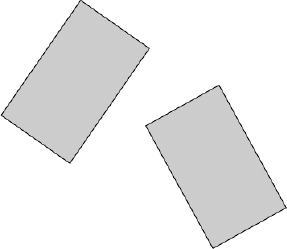
These are called oriented bounding boxes (OBBs). They're widely used in games, most obviously as collision shapes for overhead driving games. Just imagine that each of the rectangles has four wheels and a fancy paint job, and I'm sure you'll see what I mean.
There are two important things that you need to know about OBBs if you want to use them for collision detection:
You can use all the SAT principles that we've looked at so far to find the collision.
Because rectangles form 90-degree angles, you don't need to project the shapes onto the axis normals. This makes testing for collisions with OBBs much easier than with other angled polygons like triangles, where the angles aren't at 90 degrees.
Let's see how we can apply our knowledge of the SAT to this problem.
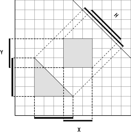
Find the axes. How many axes are there? Each rectangle has four sides, but two of those sides are aligned to the same axis. That means that there are only four axes between the two rectangles that we need to worry about, as shown in Figure 4-32. As you can see, each axis matches the rectangles' top or bottom and left or right sides.
Project each shape onto each axis. Two rectangles projected onto four axes means that you need to do a total of eight projections. This can make for a rather chaotic-looking diagram, so I've broken this step into three diagrams. Figure 4-33 shows the projections of the left rectangle onto the axes. Figure 4-34 shows all the projections of the right rectangle onto the axes. If we put all these projections together, we end up with Figure 4-35.
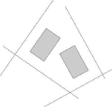
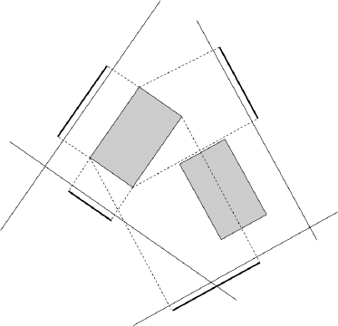
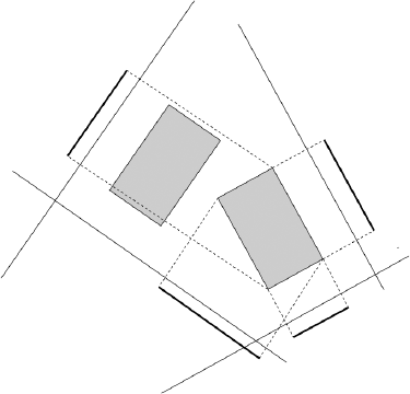
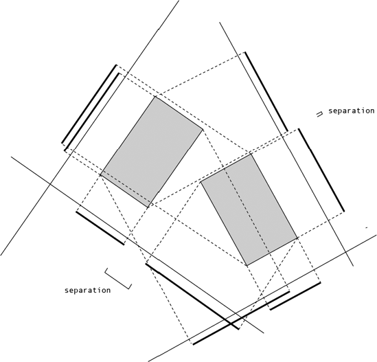
Figure 4.35. With all projections visible, you can see the separating axes. This proves that the shapes don't overlap.
In addition to giving Mondrian a run for his money, this diagram is interesting for another reason. You can clearly see that there are two separating axes. According to the SAT, all axes need to overlap if the shapes themselves are overlapping, so this is proof that the shapes don't overlap.
Will this still hold together if the shapes themselves are actually overlapping? Figure 4-36 shows what this looks like. You can see that collision occurs on the axis with the smallest amount of overlap.
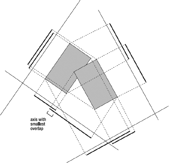
Figure 4.36. When the shapes overlap, the collision is occurring on the axis with the smallest amount of overlap.
Here's how to resolve the collision:
Create a collision vector. Multiply the collision axis's
dxanddyvalues by the amount of overlap.Move the colliding rectangle out of the collision using the collision vector's
vxandvy. If both rectangles are moving, split the difference using the same approach we looked at in Chapter 3 for dealing with two moving circles.Use the axis and axis's normal to calculate the bounce and friction.
These are the standard steps that we've been using to resolve collisions, so they should be pretty familiar to you by now. All these calculations will be much easier to do if you project the rectangles' half widths and half heights.
When I said that this example was going to be like a Caribbean holiday, I actually meant that it was going to be a Caribbean holiday for me! Why? Because I'm going to assign you the actual work of translating these concepts into code. But as I said, it's just the usual routine of projection and separation, which should be old hat to you by now. There are many ways that you could write this code, but the best way is always your own way.
And always remember this: if you understand the pictures, you can write the code!
However...
If you're doing an overhead car-driving game, the SAT might be overkill. The SAT is good for a super-precise physics simulation, but there are simpler ways to do the collision detection that could be just as effective. Here are some options:
Surround each car by an invisible bounding circle. The collision then becomes a simple circle-versus-circle problem that we looked at in Chapter 3.
For more precision, use two circles for each car: one for the front of the car and another for the back.
Just check for collisions with the corner points. Each car has four corners, so check each point against the other car's side. You can use the same techniques we used in Chapter 2. This would give you as much precision as the SAT approach and might be at least as efficient.
Simple solutions are often the best.
You know about circles. You know about squares. You know about triangles. But what if you want to mix circles and squares and triangles together, as in Figure 4-37?
This is the kind of collision horror scenario that can turn the blood cold of even the most battle-hardened Flash game designer. But it's not as difficult as you might think. It's just a matter of applying a bit of logic to the skills you already have. Let's see how.
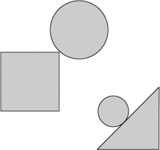
The problem we need to solve is how to deal with the corners. In fact, it's the same problem we needed solve when working out how to deal with the corners in collisions between circles and lines in Chapter 3. It means that to solve a collision between a circle and a square, you need to break it into two parts:
When the circle is closer to the sides of the square than it is to the corners, it becomes a rectangle-versus-rectangle collision problem.
When the circle is closer to any of the corners than it is to the sides, it becomes a circle-versus-particle collision problem. The x and y coordinates of the square's corners are the particles.
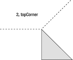
To know when to use which collision strategy is just a matter of logic, and this is not at all hard to work out. You just need to find out which region of space (Voronoi region) the circle occupies, and apply the correct collision strategy for that region. Figure 4-38 illustrates where these regions are and which strategy to use for each.
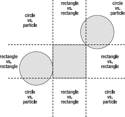
You can figure out which region the circle is in by comparing its center position to the square's position, plus its half height and half width.
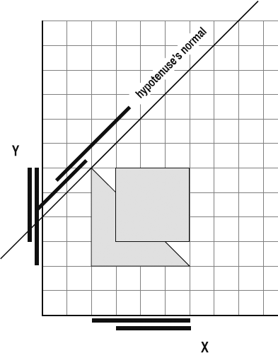
When the circle is in a rectangle-versus-rectangle region, it literally becomes a square for collision purposes, as shown in Figure 4-39. It might look like a circle on the stage, but the collision code sees it as a square.
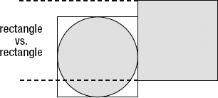
Figure 4.39. The collision code treats the circle like a square when it's in a rectangle-versus-rectangle region.
When the circle is in a circle-versus-particle region, it completely ignores the square shape and just checks for a collision with the square's closest corner point, as shown in Figure 4-40. This is the same circle-versus-particle collision strategy we looked at in Chapter 3.
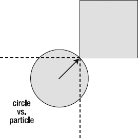
Figure 4.40. The circle checks for a collision with the corner point and ignores the square completely.
Once you understand this, the logic behind selecting the correct collision strategy almost writes itself. But to help you get started, look at CircleVsRectangle in the source files, which implements this system, as shown in Figure 4-41. That's right, my holiday is over!
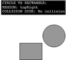
The following is the section of code from the CircleVsRectangle application class that finds the region in which the circle resides. (_r1 is the rectangle, and _c1 is the circle.) It compares the circle's position to the rectangle's position and size, and figures out which of the eight regions it currently occupies.
//Is the circle above the rectangle's top edge?if(_c1.yPos < _r1.yPos - _r1.height * 0.5) {//If it is, we need to check whether it's in the//top left, top center or top right
if(_c1.xPos < _r1.xPos - _r1.width * 0.5)
  {
    region = "topLeft";
  }
  else if (_c1.xPos > _r1.xPos + _r1.width * 0.5)
  {
    region = "topRight";
  }
  else
  {
    region = "topMiddle";
  }
}
//The circle isn't above the top edge, so it might be
//below the bottom edge
else if (_c1.yPos > _r1.yPos + _r1.height * 0.5)
{
  //If it is, we need to check whether it's in the
  //bottom left, bottom center or bottom right
  if(_c1.xPos < _r1.xPos - _r1.width * 0.5)
  {
    region = "bottomLeft";
  }
  else if (_c1.xPos > _r1.xPos + _r1.width * 0.5)
  {
    region = "bottomRight";
  }
  else
  {
    region = "bottomMiddle";
  }
}
//The circle isn't above the top edge or below the bottom
//edge, so it must be on the left or right side
else
{
  if(_c1.xPos < _r1.xPos - _r1.width * 0.5)
  {
    region = "leftMiddle";
  }
  else
  {
    region = "rightMiddle";
  }
}
Next, the code uses the region value to figure out which collision strategy to use. It chooses either a circle-versus-point strategy or a rectangle-versus-rectangle strategy, depending in which region the circle resides. The following is the code from the enterFrameHandler that does this. This is all code that you've seen from earlier examples.
//If the circle is in the topMiddle,//bottomMiddle, leftMiddle or rightMiddle//perform a standard rectangle vs. rectangle collision checkif(region == "topMiddle" || region == "bottomMiddle" || region == "leftMiddle" || region == "rightMiddle") {//Check whether the projection on//the x axis (in this case the v0's vx)//is less than the combined half widthsif(Math.abs(_v0.vx) < _c1.width * 0.5 + _r1.width * 0.5) {//A collision might be occurring. Check the other//projection on the y axis (v0's vy)if(Math.abs(_v0.vy) < _c1.height * 0.5 + _r1.height * 0.5) {//A collision has occurred//Find out the size of the overlap on both the x and y axesvar overlap_X:Number = _c1.width * 0.5 + _r1.width * 0.5 - Math.abs(_v0.vx); var overlap_Y:Number = _c1.height * 0.5 + _r1.height * 0.5 - Math.abs(_v0.vy);//The collision has occurred on the axis with the//*smallest* amount of overlap. Let's figure out which//axis that isif(overlap_X >= overlap_Y) {//The collision is happening on the x axis//But on which side? v0's vy can tell usif(_v0.vy > 0) { _collisionSide = "Top"; _c1.setY = _c1.yPos - overlap_Y; }
else
        {
          _collisionSide = "Bottom";
          _c1.setY = _c1.yPos + overlap_Y;
        }
        //Plot the x axis at r1's position
        var xAxis:VectorModel
          = new VectorModel
          (
            _c1.xPos - _r1.width * 0.5,
            _c1.yPos,
            _c1.xPos + _r1.height * 0.5,
            _c1.yPos
          );

        VectorMath.bounceOnPlane(_c1, xAxis, 0.1, 0.98);
      }
      else
      {

        //The collision is happening on the y axis
        //But on which side? v0's vx can tell us
        if(_v0.vx > 0)
        {
          _collisionSide = "Left";
          _c1.setX = _c1.xPos - overlap_X;
        }
        else
        {
          _collisionSide = "Right";
          _c1.setX = _c1.xPos + overlap_X;
        }

        //Plot the y axis at r1's position
        var yAxis:VectorModel
          = new VectorModel
          (
            _c1.xPos,
            _c1.yPos - _r1.height * 0.5,
            _c1.xPos,
            _c1.yPos + _r1.height * 0.5
          );

        VectorMath.bounceOnPlane(_c1, yAxis, 0.1, 0.98);
      }
    }
else
{
_collisionSide = "No collision";
}
}
else
{
_collisionSide = "No collision";
}
}
//The circle isn't in danger of intersecting
//with any of the rectangle's planes,
//so it has to be closer to one of the four corners
//The checkCornerCollision method does the
//work of the collision detection
//It takes four arguments:
//1. The CircleModel object
//2. The x position of the corner
//3. The y position of the corner
//4. The bounce multiplier which
//determines the amount of "bounciness"
if(region == "topLeft")
{
checkCornerCollision
(
_c1,
_r1.xPos - _r1.width * 0.5,
_r1.yPos - _r1.height * 0.5,
0.6
);
}
else if(region == "topRight")
{
checkCornerCollision
(
_c1,
_r1.xPos + _r1.width * 0.5,_r1.yPos - _r1.height * 0.5,
0.6
);
}
else if(region == "bottomLeft")
{
checkCornerCollision
(
_c1,
_r1.xPos - _r1.width * 0.5,
_r1.yPos + _r1.height * 0.5,
0.6
);
}
else if(region == "bottomRight")
{
checkCornerCollision
(
_c1,
_r1.xPos + _r1.width * 0.5,
_r1.yPos + _r1.height * 0.5,
0.6
);
}The checkCornerCollision method bounces the circle off the square's corners.
public function checkCornerCollision
  (
    circle:CircleModel,
    corner_X:Number,
    corner_Y:Number,
    bounceAmount:Number
  ):void
{
  //Vector between circle and particle (the square's corner)
  var v0:VectorModel
    = new VectorModel
    (
      circle.xPos,
      circle.yPos,
      corner_X,
      corner_Y
    );

  if(v0.m < circle.radius)
  {

    //Find the amount of overlap
    var overlap:Number = circle.radius - v0.m;

    circle.setX = circle.xPos - (overlap * v0.dx);
    circle.setY = circle.yPos - (overlap * v0.dy);
    //circle's motion vector
    var v1:VectorModel
      = new VectorModel
      (
        circle.xPos,
        circle.yPos,
circle.xPos + circle.vx,
circle.yPos + circle.vy
);
//Create the circle's bounce vector
var bounce:VectorModel = VectorMath.bounce(v1, v0.ln);
//Bounce the circle
circle.vx = bounce.vx * bounceAmount;
circle.vy = bounce.vy * bounceAmount;
}
}This code is almost identical to the circle-versus-particle code we looked in Chapter 3.
To check for a collision between a circle and a triangle's hypotenuse, we apply a circle-versus-line collision strategy. This is the same collision strategy we covered at the beginning of Chapter 3. The hypotenuse also determines how the regions are divided, as shown in Figure 4-42.
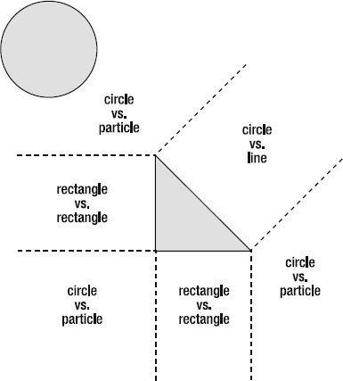
Figure 4.42. Use a circle-versus-line collision strategy to check for a collision between the circle and the triangle's hypotenuse.
To find out whether the circle is within the hypotenuse region, we just need to reach into our bag of tricks and roll this one onto the table:
Extend a vector between the center of the circle and the start point of the hypotenuse.
If the dot product between this vector and the hypotenuse is less than zero and greater than the negative value of the hypotenuse's magnitude, you know that it's within this region.
Figure 4-43 shows what you need to find.
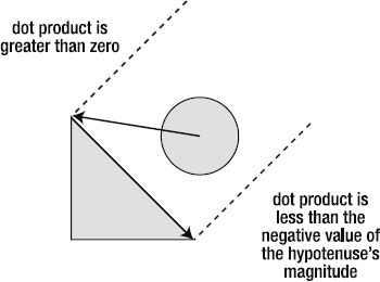
Figure 4.43. The dot product of the two vectors will tell you whether the circle is within the hypotenuse's region.
Check back to Chapter 3 for a quick review of how this works, just in case you've forgotten.
You'll find a working example in the CircleVsTriangle folder, as shown in Figure 4-44.

Again, we just need to use logic to figure out in which region the circle resides. However, there are a few little minefields to sidestep that won't be obvious at first, and I'll point these out as we walk through the example.
Let's take a look at the code in the source that finds the regions. There are a few different ways you could code this, and although this one isn't the most efficient, it's the most understandable.
//Which region is the circle in?//First check the hypotenuseif(dp1 < 0 && dp1 > -_hypotenuse.m && _c1.xPos > _t1.xPos - _t1.width / 2 && _c1.yPos < _t1.yPos + _t1.height / 2) { region = "hypotenuse"; }//If the circle isn't in the hypotenuse region,//check the other possibilitieselse {//Check the top cornerif(_c1.yPos < _t1.yPos - _t1.height / 2) { region = "topCorner"; }//The circle isn't above the top edge, so it might be//below the bottom edgeelse if (_c1.yPos > _t1.yPos + _t1.height / 2) {//If it is, we need to check whether it's in the//bottom left, bottom center or bottom rightif(_c1.xPos < _t1.xPos - _t1.width / 2) { region = "bottomLeftCorner"; } else if(_c1.xPos > _t1.xPos + _t1.width / 2) { region = "bottomRightCorner"; } else { region = "bottomMiddle"; } }
//The circle isn't above the top edge or below the bottom//edge, so it must be on the left or right sideelse { if(_c1.xPos < _t1.xPos - _t1.width / 2) { region = "leftMiddle"; }//If all the previous tests fail, then//the circle must be within the wedge of space between the//bottom-right corner and the the hypotenuse's regionelse { region = "bottomRightCorner"; } } }
First, we check whether the circle is in the hypotenuse region, as shown in Figure 4-45.
if(dp1 < 0
&& dp1 > -_hypotenuse.m
&& _c1.xPos > _t1.xPos - _t1.width / 2
&& _c1.yPos < _t1.yPos + _t1.height / 2)
{
  region = "hypotenuse";
}
In addition to checking the value of the dot product, we also must make sure that the circle is above the bottom of the triangle and to the right of its left edge. This is important because the dot product condition could be true if the circle is on the opposite side of the hypotenuse. These extra checks make sure that it's on the correct side of the triangle.
Next, check the top corner, as shown in Figure 4-46. Because we checked the hypotenuse first, we know that the circle can't possibly be in the hypotenuse region. This makes the conditional statement for this odd-shaped region very simple.
else
{
  if(_c1.yPos < _t1.yPos - _t1.height / 2)
  {
    region = "topCorner";
  }
We've eliminated the top regions of the circle, so we can now check the bottom and sides. The next bit of code checks whether the circle is below the triangle. There are actually three regions below the triangle, so we need to check for each of them, as shown in Figure 4-47.
else if (_c1.yPos > _t1.yPos + _t1.height / 2)
{

  if(_c1.xPos < _t1.xPos - _t1.width / 2)
  {
    region = "bottomLeftCorner";
  }
  else if(_c1.xPos > _t1.xPos + _t1.width / 2)
  {
    region = "bottomRightCorner";
  }
  else
  {
    region = "bottomMiddle";
  }
}
There's one little anomaly that's not accounted for here, but the next step will fix this oversight.

Lastly, we need to check the right and left sides. Most of the right side belongs to the hypotenuse region, except for a wedge of space just below it. This wedge belongs to the bottomRightCorner, as shown in Figure 4-48.
else
{
  if(_c1.xPos < _t1.xPos - _t1.width / 2)
  {
    region = "leftMiddle";
  }
  else
  {
    region = "bottomRightCorner";
  }
}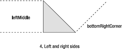
When you're working out Voronoi regions for polygons like this, it's often a good idea to draw them with a pencil on graph paper first, so that you can catch little snafus like this before you start coding. Paper and pencil—a wonderful medium!
Note
When you deal with the circle-versus-hypotenuse collision, you can use the same circle-versus-line technique we used in Chapter 3. It will work just fine. However, the CircleVsTriangle source code handles it differently. It uses the technique that we used to check for an overlap between the rectangle and the hypotenuse. But instead of projecting the rectangle's half width and half height, it projects the circle's radius. Neither method is necessarily better than the other, but it's important to know that there's often more than one way to solve a problem. Check the source code for details.
In the chapter's source files you'll find a folder called CircleVsTriangleLeft. The application class allows you to create triangles that are facing either to the right or to the left, as shown in Figure 4-49.

To create a left-facing triangle, use "left" as an argument in the TriangleModel's constructor.
private var _t1:TriangleModel = new TriangleModel(60, 80, "left");TriangleModel objects have a property called hypotenuse that returns the triangle's hypotenuse as a VectorModel object. The hypotenuse vector is calculated differently depending on whether the triangle's inclination is "left" or "right".
The logic used to find the Voronoi regions for left-facing triangles is exactly the same as for right-facing triangles, but some of the values are reversed. You'll find all the details in the source itself—there aren't any surprises.
Now it's time to see how everything you've learned works in actual games. We'll look at two case studies that demonstrate the techniques we've covered so far, as well as some new ones. These case studies supply several important items you can use for your own games:
A complex physics-based game environment for platform and action games
A prototype for a breakout-style game
A flexible template for building games that can be scaled to accommodate games of almost any size or complexity
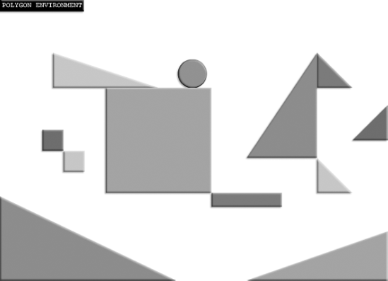
We've spent this chapter making the building blocks of game environments. And what do you do with building blocks? Build things! So, like an industrious three-year-old, I emptied my bag of blocks on the kitchen floor and came up with PolygonEnvironment, which you'll find in the chapter's source files. Figure 4-50 shows the environment.
Use the mouse or arrow keys to explore the environment. The circle can bounce, roll, slide, and find corners to rest in, as shown in Figure 4-51.
The shapes that you can see on the stage use the RectangleModel, TriangleModel, and CircleModel classes. But I've created new view classes that give the shapes a beveled appearance: RectangleBlockView, TriangleBlockView, and CircleBlockView. (You'll find these classes in the com.friendsofed.gameElements.primitives package.)
The rectangles are pushed into a _rectangles array, and the triangles are pushed into a _triangles array. The enterFrameHandler loops through each array to check each type of shape for collisions with the circles.
for(var i:int = 0; i < _triangles.length; i++)
{
  circleVsTriangle(_c1, _triangles[i]);
}

for(var j:int = 0; j < _rectangles.length; j++)
{
  circleVsRectangle(_c1, _rectangles[j]);
}
PolygonEnvironment uses all the techniques and all the code we've covered in this chapter. I've intentionally kept all the code in one big application class so that you can easily see how it fits together.
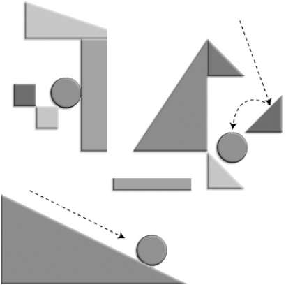
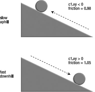
There's a new feature in PolygonEnvironment. When the circle rolls up and down the sloping triangles, it behaves like a real ball. It rolls slowly uphill and accelerates quickly downhill. And if it rolls uphill, it will gradually slow down, stop, and roll back down the hill again. This is exactly the effect that gravity has on balls rolling on real hills in the real world.
I haven't made any changes in how gravity affects the circle to achieve this effect. The star of the show this time is friction. I've made an addition to the code so that slopes have less friction when the circle is traveling downhill, and more friction when the circle is traveling uphill.
To figure out whether the circle is traveling uphill or downhill, you need to check its velocity. If its velocity is greater than zero, then you know its traveling downhill, and you need to reduce friction. (The friction value is calculated just before the bounceOnPlane method.)
var friction:Number;
c1.vy > 0 ? friction = 1.05 : friction = 0.98;
VectorMath.bounceOnPlane(c1, t1.hypotenuse, 0.6, friction);
If the circle is traveling downhill, friction will be greater than 1. The effect of this is cumulative, so that the circle gradually picks up speed as it rolls downhill, as shown in Figure 4-52. You'll find this bit of code in the circleVsTriangle method that checks for collisions between the circle and the triangles.
With proper game graphics to replace these example shapes, you're well on your way to building game environments that are as complex as any you might need, for a huge variety of games. If you can start to see shapes as containers or bounding boxes for game objects, you'll realize how valuable this chapter has been.
The code used in PolygonEnvironment is predictable, but there's also a lot of it—more than 600 lines the last time I checked. If you add some enemies, AI, menus, and a scoring system, you'll soon end up with an application class that's thousands of lines long, and that would be completely unmanageable.
The solution is to break down these responsibilities into separate classes. That's easy enough to say, but how do you do it? If you take the wrong approach, you can end up with folders and subfolders full of classes, and start to forget halfway through the project which classes do what or how they communicate with one another. Classes alone are not answer.
Good planning could solve some of this, but if you're designing a new type of game for the very first time, you often won't know what to anticipate. Game designers like to work on the cutting edge, and the inspired thrill of trying something new in the middle of a project is what drives innovation and keeps games fresh.
Note
There is a technical term for "trying lots of new stuff until something works." Game designers call this iteration. Iteration, as a design style, means trying something new, observing its effect, and then using what you've learned to try again. That's almost always how game designers work. So, the next time your boss asks you to describe your work methodology, you can reply with confidence, "I employ the iterative process." It will sound much better than saying, "I make it up as I go along."
So, yes, you can plan, but you also need to plan for the unexpected. And expect that the unexpected will become the plan! There's certainly no single solution to this, but the next section suggests a good one.
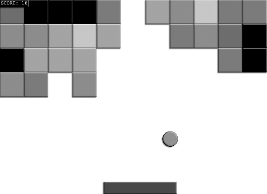
Our first complete game prototype of the book is the imaginatively titled BlockGame, which you'll find in the chapter's source files. Run the SWF, and you'll see that it's a familiar paddle-and-brick game in the style of Breakout, as shown in Figure 4-53. Use the mouse to move the paddle and break the bricks. When 30 bricks have been hit, a "Game Over" message is displayed.
This is a bare-bones skeleton of a game, which I've kept as simple as possible so that you can clearly see how all the pieces fit together. It's important for two reasons:
It employs the circle-versus-square collision system that we looked in this chapter, which is a core game-design technique. It shows that it's just as effective when both the circle and square are in motion.
It's structured like a complete game. You can use this structure to build games of great complexity and flexibility once you understand it.
Let's pull this example apart and see how all the pieces fit together.
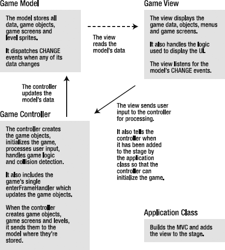
The game is built around an all-encompassing MVC structure. You understand how the MVC concept works with individual game objects, like spaceships. What you need to do now is expand that concept so that it envelops an entire game. (If you need a refresher on how MVC works, be sure the review the relevant sections in Chapter 1.)
The basic concept isn't hard to grasp, but some of the details aren't obvious right away. Here are the main components:
Game model: A class that stores all the data of the game. This includes numerical data, such as the score. That's easy to understand, but what's a little trickier to grasp is that it also has all the visual things you can see in the game. This includes the game objects (like the player, enemies, and platforms) and the
sprites, which contain the entire game screen. Everything that exists in the game must be contained in the game model. It's like a big, centralized storehouse where all the other classes know they can look if they need something. This will be a bit confusing at first, but we'll look at how this works practically in the pages ahead.Game view: A class that uses the game model data to display the game. It's responsible for adding and removing game elements to the stage. This includes game levels, menus, and score displays. It doesn't handle any game logic; however, it includes logic for the user interface, such as what to do when a player clicks a button. And it also includes any logic it needs to display game data, like the score or to switch levels.
Game controller. All the game logic: initialization, level setup, collision detection, and scoring. It also creates all the objects used in the game and adds them to the game model. This is the most complex class.
Application class: This is the game's common point of entry. Use the application class to compose the MVC system and add the game view to the stage. The application class has privileged access to the
stageobject, so we need to feed it a reference to thestageto the view and controller classes.
Figure 4-54 shows how this all fits together.
Take a look at the BlockGame folder, and you'll find four files, each of which corresponds with the preceding main components:
BlockGame.as(the application class)GameModel.asGameView.asGameController.as
We'll take a look at each of these in turn and see how they work together to build the game.
The application class is the hook that gets the game up and running. It composes the MVC framework and adds the view to the stage. Here's the entire BlockGame application class:
package
{
  import flash.events.Event;
  import flash.display.Sprite;

  [SWF(width="550", height="400", backgroundColor="#FFFFFF", frameRate="60")]

  public class BlockGame extends Sprite
  {
    private var _gameModel:GameModel
      = new GameModel();
    private var _gameController:GameController
      = new GameController(_gameModel, stage);
private var _gameView:GameView
= new GameView(_gameModel, _gameController, stage);
public function BlockGame():void
{
addChild(_gameView);
}
}
}When the _gameView is added to the stage, it alerts the _gameController, which initializes the game.
The GameModel is a big storage container for everything in the game. It contains the values for all the game's data:
The score
The number of rows and columns used to plot the blocks
The width and height of each block
The GameController uses this data to create the game and monitor the game's progress.
The GameModel also stores all the visible objects in the game:
References to the paddle and ball
Arrays that store the block models and block views
What's important to keep in mind is that the GameModel doesn't create any of these objects. The GameController creates them when the game is initialized. However, the GameModel needs to have storage containers ready for them, when the models are first created.
The GameModel does create one object, however. And it's a somewhat unusual object: a screen sprite. This represents the visible stage. The GameController will add the paddle, ball, and block views to this sprite when it initializes the game. The GameView adds this sprite to the stage when the game starts. It's the game screen that you can see when you play the game.
Keep your eye on this screen object! It's the key to understanding how our whole MVC system works. You'll see how this screen sprite is used by the GameController and GameView soon.
It's important to understand that the screen sprite is part of the GameModel's data. This highlights an important point: everything in the game is data. Data isn't just numbers and strings. It's also all visible objects and their container sprites on the stage. And in bigger games, this includes complete levels and menus.
The strategy behind this is to pack everything in the game into the GameModel so that it can be found by any object that needs it. The GameModel doesn't make any decisions about what to do with this data or how to display it, but makes it accessible in one central location to any other class or object that needs it.
Here's the entire GameModel class:
package
{
  import flash.events.Event;
  import flash.events.EventDispatcher;
  import flash.display.Sprite;
  import com.friendsofed.gameElements.primitives.*;

  public class GameModel extends EventDispatcher
  {
    //The number of rows and columns
    public const ROWS:uint = 4;
    public const COLUMNS:uint = 11;

    //The GameModel needs references to the game objects
    //The paddle and the ball
    public var paddle:RectangleModel;
    public var ball:CircleModel;

    //The blocks
    public var blockWidth:uint = 50;
    public var blockHeight:uint = 50;
    public var blockModels:Array = [];
    public var blockViews:Array = [];

    //The game screen, which is visible on the stage.
    //The GameController will add objects to this Sprite
    //and the GameView will add it to the stage.
    public var screen:Sprite = new Sprite();

    //Game variables
    private var _score:uint = 0;
    public var maxScore:uint = 30;

    public function GameModel():void
    {
    }

    //score
    public function get score():uint
    {
      return _score;
    }
public function set score(value:uint):void
{
_score = value;
dispatchEvent(new Event(Event.CHANGE));
}
}
}Can you see that the screen sprite is being initialized in the GameModel?
The GameView does these jobs:
Adds the
GameModel'sscreensprite to the stageCreates a status box that displays the score
Listens for changes to the
GameModel's score and displays it in the status boxFigures out if the score is greater or less than the
GameModel'smaxScoreIf the score is greater than the
GameModel'smaxScore, removes thescreensprite and displays a "Game Over" message in the status box
The GameView doesn't actually build the level; that's the job of the GameController. It just handles the bigger picture of adding and removing the screen sprite on the stage and displaying the score and "Game Over" message.
Here's the entire GameView class:
package
{
  import flash.events.Event;
  import flash.display.Sprite;
  import flash.ui.Mouse;
  import com.friendsofed.gameElements.primitives.*;
  import com.friendsofed.utils.*;

  public class GameView extends Sprite
  {
    private var _gameModel:GameModel;
    private var _gameController:GameController;
    private var _stage:Object;

    //Status box to display the score
    private var _statusBox:StatusBox = new StatusBox;
public function GameView
(
model:GameModel,
controller:GameController,
stage:Object
):void
{
_gameModel = model;
_gameModel.addEventListener(Event.CHANGE, changeHandler);
_gameController = controller;
this._stage = stage;
addEventListener(Event.ADDED_TO_STAGE, addedToStageHandler);
}
private function addedToStageHandler(event:Event):void
{
//Display the screen Sprite
addChild(_gameModel.screen);
//Add the status box
addChild(_statusBox);
_statusBox.text = "SCORE:";
//Hide the mouse
Mouse.hide();
//Add listeners
addEventListener(Event.REMOVED_FROM_STAGE, removedFromStageHandler);
}
private function removedFromStageHandler(event:Event):void
{
removeEventListener
(Event.ADDED_TO_STAGE, addedToStageHandler);
removeEventListener
(Event.REMOVED_FROM_STAGE, removedFromStageHandler);
}
private function changeHandler(event:Event):void
{
if(_gameModel.score < _gameModel.maxScore)
{
_statusBox.text = "SCORE: " + _gameModel.score;
}
else
{
removeChild(_gameModel.screen);
_statusBox.text = "GAME OVER";
_statusBox.text += "
" + "SCORE: " + _gameModel.score;_statusBox.x = _stage.stageWidth / 2 - _statusBox.width / 2;
_statusBox.y = _stage.stageHeight / 2 - _statusBox.height;
Mouse.show();
}
}
}
}The GameController has a lot of work to do:
Create all the objects and add them to the
GameModel'sscreenspriteConstruct the level, and initialize the colors and positions of all the game objects
Run the game's single
enterFrameHandlerthat updates the paddle and ball, and check for collisionsContain all the collision methods
Update the score, which it sends to the
GameModel
The GameController class is listed here, but to save a bit of space, I've omitted the collision code. It's identical to the code that we covered earlier in the chapter, so refer to the source for the specifics if you need them. Some of what's happening will be a bit confusing at first glance, so we'll take a look at some of the details after the code listing.
package
{
  import flash.events.Event;
  import flash.events.KeyboardEvent;
  import flash.ui.Keyboard;
  import flash.events.MouseEvent;
  import flash.display.DisplayObject;
  import com.friendsofed.utils.*;
  import com.friendsofed.gameElements.primitives.*;
  import com.friendsofed.vector.*;

  public class GameController
  {
    private var _gameModel:GameModel;
    private var _stage:Object;

    //The paddle
    private var _paddleModel:RectangleModel;
    private var _MousePaddleController:MousePaddleController;
    private var _MousePaddleView:MousePaddleView;
    private var _paddleView:RectangleBlockView;
//The ballprivate var _ballModel:CircleModel; private var _ballView:CircleBlockView; public function GameController(model:GameModel, stage:Object):void { _gameModel = model; _stage = stage; _stage.addEventListener(Event.ENTER_FRAME, enterFrameHandler); createLevel(); } public function createLevel():void {//Create the paddle_paddleModel = new RectangleModel(150, 25); _MousePaddleController = new MousePaddleController(_paddleModel); _MousePaddleView = new MousePaddleView (_paddleModel, _MousePaddleController, _stage); _paddleView = new RectangleBlockView(_paddleModel);//Add the _paddleModel to the GameModel and the _paddleView//to the GameModel's screen Sprite_gameModel.paddle = _paddleModel; _gameModel.screen.addChild(_paddleView);//Position the paddle at the bottom of the stage and give it a color_gameModel.paddle.setX = _stage.stageWidth / 2; _gameModel.paddle.setY = _stage.stageHeight - _gameModel.paddle.height / 2; _gameModel.paddle.color = 0x4E4E4E;//Create the ball_ballModel = new CircleModel(15); _ballView = new CircleBlockView(_ballModel);//Add the _ballModel to the GameModel and the _ballView//to the GameModel's screen Sprite_gameModel.ball = _ballModel; _gameModel.screen.addChild(_ballView);//Position the ball, give it an initial velocity//and set its friction and color_gameModel.ball.setX = 275; _gameModel.ball.setY = 250; _gameModel.ball.vy = 5; _gameModel.ball.vx = 3; _gameModel.ball.friction = 1; _gameModel.ball.color = 0xC27D96;
//Create the blocks and position them in rows and columns//Array to store block colorsvar blockColors:Array = [0xBDCEA8, 0x90AE9A, 0x769690, 0x6C8388, 0x061737F]; var currentBlock:uint = 0; for(var columns:int = 0; columns < _gameModel.COLUMNS; columns++) { for(var rows:int = 0; rows < _gameModel.ROWS; rows++) {//Create the block modelsvar blockModel:RectangleModel = new RectangleModel ( _gameModel.blockWidth, _gameModel.blockHeight );//Position the blockModels in a gridblockModel.setX = columns * _gameModel.blockWidth + _gameModel.blockWidth / 2; blockModel.setY = rows * _gameModel.blockHeight + _gameModel.blockHeight / 2;//Assign a random colorvar color:uint = Math.round(Math.random() * blockColors.length); blockModel.color = blockColors[color];//Push the block model into the GameModel's blocks array_gameModel.blockModels.push(blockModel);//Create the block views and add it to//the GameModel's screen spritevar blockView:RectangleBlockView = new RectangleBlockView(blockModel); _gameModel.blockViews.push(blockView); _gameModel.screen.addChild(blockView);//Increment the currentBlock counter to plot the next elementcurrentBlock++; } } }
private function enterFrameHandler(event:Event):void
  {
    //Update the paddle and ball Models
    _gameModel.paddle.update();
    StageBoundaries.stop(_gameModel.paddle, _stage);

    _gameModel.ball.update();
    StageBoundaries.bounce(_gameModel.ball, _stage);

    //Check for a collision between the ball and the paddle
    circleVsRectangle(_gameModel.ball, _gameModel.paddle);

    //Check for a collision between the ball and the blocks
    //by looping through all the elements in the blockModels
    //array and calling the circleVsRectangle collision method
    for(var i:int = 0; i < _gameModel.blockModels.length; i++)
    {
      circleVsRectangle
        (_gameModel.ball, _gameModel.blockModels[i]);

      //Remove the block if it has been hit. If it has,
      //its "visible" property will have been set to "false"
      //by the circleVsRectangle method above
      if(_gameModel.blockModels[i].visible == false)
      {
        _gameModel.screen.removeChild(_gameModel.blockViews[i]);
        _gameModel.blockViews.splice(i, 1);
        _gameModel.blockModels.splice(i, 1);

        //Update the score
        _gameModel.score++;
        }
    }
}

    //The main collision method:
    public function circleVsRectangle(c1:CircleModel, r1:RectangleModel):void
    {
      //... Standard circle vs. rectangle code from the earlier in the chapter.
      //Check the source code for details.

      //If a collision is found on the sides of the
      //rectangle and the rectangle isn't
      //the player's paddle, then the rectangle's
      //"visible" property is set to "false".
      //This flags it to be removed from the blockModels
      //and blockViews arrays in the enterFrameHandler
if(r1 != _gameModel.paddle)
{
r1.visible = false;
}
//If a collision isn't found on the sides of the rectangle,
//this method calls checkCornerCollision to check whether
//the ball has hit any of the corners
}
//Check for a collision with the rectangle's four corners
private function checkCornerCollision
(
circle:CircleModel,
corner_X:Number,
corner_Y:Number,
bounceAmount:Number
):void
{
//...Bounce the ball if it hits a corner, set the
//rectangle's visible property to "false" so that it's
//flagged for removal by the enterFrameHandler
if(r1 != _gameModel.paddle)
{
r1.visible = false;
}
}
}
}The GameController is the brains of the game. It takes on many of the roles that had been the responsibility of the application classes in our previous example files.
The first thing it does is to create the objects. The paddle object is its own self-contained MVC system.
_paddleModel = new RectangleModel(150, 25);
_MousePaddleController = new MousePaddleController(_paddleModel);
_MousePaddleView = new MousePaddleView
  (_paddleModel, _MousePaddleController, _stage);
_paddleView = new RectangleBlockView(_paddleModel);
The MousePaddleController very simply fixes the paddle's x position to the mouse position. (You'll find it in the com.friendsofed.gameElements. primitives package.)
The next bit is interesting: the paddle model is passed to the GameModel's paddle property.
_gameModel.paddle = _paddleModel;
From now on, whenever the GameController needs to access the paddle, it does so through the GameModel. This is centralized so that other objects, like the GameView, can access it. The efficiency of this won't be immediately obvious in a small example, but in a complex game, it means that multiple views can access the same data from a common location in the GameModel.
Next, the paddle view is added to the GameModel's screen sprite.
_gameModel.screen.addChild(_paddleView);
All the views of the game objects will be added to the GameModel's screen sprite. The GameView can then access and display them. Figure 4-55 illustrates how this all fits together.
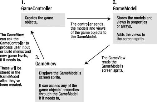
Figure 4.55. The GameController creates the game objects and stores them in the GameModel. The GameView reads them from the GameModel.
The GameController also gives the game objects their initial positions and colors.
_gameModel.paddle.setX = _stage.stageWidth * 0.5;
_gameModel.paddle.setY = _stage.stageHeight - _gameModel.paddle.height * 0.5;
_gameModel.paddle.color = 0x4E4E4E;
But hold on a moment! This is visual information relating to the display. In an MVC system, isn't that the job of the view? Shouldn't positions and colors be assigned in the GameView?
Let's review what we know about MVC:
Only the controller should change values in the model.
The view should only read the model's data.
If the view needs any values changed, it should pass that request to the controller first.
Our GameController code is sticking to this formula. The x, y, and color information are all properties of objects that exist in the GameModel. That means that only the GameController should be allowed to change it. It's visual data, yes, but it's data. All data—visual or otherwise—should be centralized in the GameModel, and only the GameController can change it.
However, that doesn't prevent the GameView from creating its own objects and accessing them directly. In this simple example, the GameView creates a StatusBox object to display the score. The GameModel doesn't' need to know anything about the StatusBox, because the StatusBox has nothing to do with the data of the game. It's purely for display purposes. The GameView can create and modify any other objects it needs, like borders, buttons, or menus to showcase that data. The only thing it can't do is directly change properties in the GameModel. It can't change the properties of the game objects. If it thinks it needs to, it should send all those requests to the GameController.
The last detail of this code that we should take a closer look at is the way that the GameController plots the grid of blocks. It uses a nested for loop. The outer loop plots the columns, and the inner loop plots the rows. Here's the general algorithm that's used:
//A counter variable to track the current blockvar currentBlock:uint = 0;//Columnsfor(var columns:int = 0; columns < _gameModel.COLUMNS; columns++) {//Rowsfor(var rows:int = 0; rows < _gameModel.ROWS; rows++) {//Create the blockvar block = new Block();//Set the x and y position//(assuming the block's x and y point is its center)block.x = columns * block.width + block.width * 0.5; block.y = rows * block.height + block.height * 0.5;//Push the block into an arrayblockArray.push(block);//Increment the currentBlock counter to plot the next elementcurrentBlock++; } }
This is skeletal code so that you can better understand the underlying system for plotting a grid of rectangles. The actual code in the GameController class (listed earlier) also does the additional work of assigning colors and adding the block views to the GameModel's screen sprite. It also adds the blocks' views and models to arrays so that they can easily be removed after a collision.
This algorithm for plotting a grid is another fundamental game-design technique. You're going to see it many more times in this book in various contexts.
It takes a bit of practice and a bit of discipline to code like this. The payoff is that you have an abstract model of your game running behind the scenes that any object can access. And because the data is largely decoupled from the other objects, it can be displayed or processed in an endless variety of ways without disrupting the rest of the structure.
It also doesn't make any assumption about what the content of the game is, so it's a blank slate. It will work just as well as a general structure whether you're designing a video game or an interactive information kiosk for a museum.
Using an MVC system for organizing your game is also very flexible because you can add as many new components to this system as you need to without breaking the components that are already working together. This is great for creatively designing your game while you code it. An example of this is building a multilevel game, with many game screens and different styles of play. In this simple game, there's only one level and then the game ends. But how could we expand this to create more game levels? Very simply: create a model, view, and controller for each level.
For level one, you might have three classes: LevelOneModel, LevelOneView, and LevelOneController. They would be functionally almost identical to the three classes we've just looked at. However, in a multilevel game, you would also use a GameModel, GameView, and GameController. Their tasks would be to manage the overall running of the game.
The GameModel would track the global data, like the score, that's needs to run the game, and set the overall conditions for winning and losing. Optionally, you might also find it useful to store individual levels as data in the game. This is the same concept as storing the screen sprite as data, except on a wider scope. Game levels are a kind of data, so it might make sense for GameModel to store them. This is especially true if data needs to be shared between levels. The GameModel can then act as a single resource for this data.
The GameView would switch levels and handle the game's menus and user interface. (Specific menus for each level are handled by the level's view.) It would listen for changes in the model to figure out when it should switch levels. It then would ask the GameController to create a new level.
The GameController would create the levels. Levels are complete, self-contained MVC systems in their own right. They would consist of three classes, such as LevelOneModel, LevelOneView, and LevelOneController. The details of level creation are handled by the LevelController.
Something to consider is that the LevelOneModel might also need to access to the GameModel's, data. If so, you could create the LevelOneModel like this:
private var _levelOneModel:LevelOneModel = new LevelOneModel (_gameModel);
It's also quite likely that the LevelOneController would need access to the GameModel, to alert it to update the global score, among other things. In that case, you could create the LevelOneController like this:
private var _levelOneController:LevelOneController
  = new LevelOneController(_levelOneModel, _gameModel, stage);
It's quite acceptable for a model in an MVC system to have more than one controller.
In addition to this, you'll almost certainly need two more items:
A
gameElementspackage that contains the MVC components for your game objects. This could include the player character, enemies, backgrounds, and platforms.A
Collisionclass. It's very likely that your collision code will be common to all game levels, so it makes sense to centralize it.
There are a few different ways that you could handle these specifics, but this will be enough to get you started. Figure 4-56 shows the basic file structure you might end up with a three-level game.
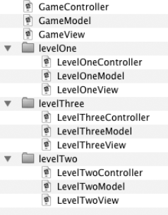
Chapter 7 takes a more detailed look at game structure using this system and how to manage a complex game. It also explains how to manage different game states.
Remember that this is merely a suggested way of organizing your code. It works, and works well, but there's no one-size-fits-all solution that will cover all game design problems. Look carefully at each game project before you start to determine whether this solution will work for you. Also, don't feel you need to understand all of this just by reading through this chapter. This is one situation where the best way to learn is to jump in and start coding a game. You'll soon find out whether this is the right system for you to use for what you're trying to accomplish.
To get you started, I've created a basic template file in the chapter's source files called GameTemplate. It's a blank template based on the BlockGame example. It includes a GameModel, GameView, GameController, and document class. There's enough there for you start filling in the details of your own game. And let me know when you're done—I'd love to play it!
In Chapter 8, we're going to take a detailed look at an alternative system to manage multiple levels using a tile-based game engine.
The core physics and geometry that we've covered so far in this book should be basic knowledge for any serious game designer. Learn it, understand it, practice it, and let it become the currency of your game-design universe. The concepts and math are as useful for making games using AS3.0, as it is for making games with Java, C++, Objective C, or some future programming language yet to be invented. You now have the skills to control the entire geometry of your space and the motion of all your game objects. You are able to handle almost any collision-detection problem that might come up. (Yes, I said "almost," because there's one more collision scenario that you still need know about, which we'll look at in the next chapter.)
The concepts that we've covered are so fundamental to game design, in any programming language or medium, that if you want to try your hand at more complex physics, you have this book as a reference to move on to the next level. All the math and concepts that we've covered have built a solid foundation for you to continue developing your skills.
In the next chapter, we're going to start putting these skills to some practical use and learn about how to use bitmaps for pixel-perfect collision and making destructible environments.