
In this chapter, we're going to peel away the veil of this mysterious realm to examine these smallest but most important components of the video game universe. With the help of a bit of easy math, vectors are the key to decoding the entire geometry of the space of your game environment. Learning how to work with them gives you unlimited control over your games.
How would you feel if you could control gravity, wind, the trajectory of bullets, and the laws of physics and thermodynamics at will? Like a character from the Matrix, you will have that kind power in your own game world.
Warning
Vectorsare not Vectors! In this chapter, vectors refer to Euclidean vectors used in geometry, not the Vector class. The Vector class is an AS3.0 typed array and is completely unrelated to Euclidean vectors. The term also doesn't refer directly to vector graphics, which are used by Flash to draw shapes, although vectors are the underlying mathematical principles on which vector graphics are based.
Vectors are lines. They have a start point and an end point. Figure 2-1 shows an example of a vector called v1. The vector starts at point A and ends at point B.
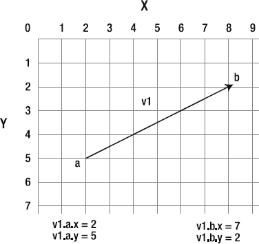
Yes, it really is what you think it is: a plain line! Vectors are just lines with a start point and an end point.
What? You were expecting something more complicated than that? Well, I'm sorry to disappoint you! But this is only the beginning of a long chapter, so there's certainly more to the story.
In this chapter, I'm going to use a simple naming convention for describing vectors. Vector names will start with v plus the number of the vector, such as v1, v2, and v3. This will help to keep the code compact and also make it easy for us to use our vectors with arrays.
In the code that we'll be looking at, the start and end points of vectors will be created as Point objects. Point objects are used to store x and y coordinates. You may have used them in the past if you ever needed to convert a display object's local coordinates to global coordinates. Here's the general code that you would use to create a vector's point A and point B:
a:Point = new Point(100, 100);
b:Point = new Point(400, 300);
Point objects have x and y properties, so you can refer to the specific point coordinates like this:
a.x
a.y
And you can set the x and y properties like this:
a.x = 450;
a.y = 348;
Let's say we have a vector called v1 and want to refer to the x coordinate of point B. We can do so like this:
v1.b.x
Usually, I would advise you to avoid short, nondescriptive variables names like these, because they're hard to read. But in the case of variables that are going to be used mainly for mathematical calculations, a coded shorthand like this is really useful. Your code will look neat and compact, rather than sprawling off the edge of your code editor, and you'll instantly know what kind of information a variable contains just by glancing at it.
Throughout this chapter, I'll introduce additional abbreviations for common vector properties. The naming conventions are not standardized, and you're free to use any other system you prefer.
What can two points that define a line tell us? If the line starts at point A and ends at point B, we can say that the vector is pointing toward point B. It has a direction.
As you can see in Figure 2-1, the vector tells you where it starts, where it ends, and the direction it's pointing toward. These are the two defining characteristics of vectors:
Length (often referred to by the more technical term magnitude)
Direction
Does that sound like some sort of information that might be of use in a game? Well, surprise, surprise—you are already using this information. It's called velocity!
Whenever a game object moves, it creates a vector. The vector is created by the object's vertical and horizontal velocity, better known as our dear friends, vx and vy, as illustrated in Figure 2-2.
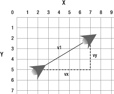
Any moving object, like our spaceship in the previous chapter, has horizontal velocity (vx) and vertical velocity (vy). When these velocities are combined, the ship moves in some direction. If the spaceship has a vx of 5 and vy of −5, it will appear to move diagonally toward the top right. And when that happens, the ship invisibly creates a vector between its previous position and its new position.
This kind of vector, which is created by an object's movement, is called a motion vector. So you've been creating and using vectors all this time without even knowing it!
You have not seen these vectors directly on the stage, but they've been there all along, like other-dimensional puppet masters pulling the strings of your game objects behind the curtains.
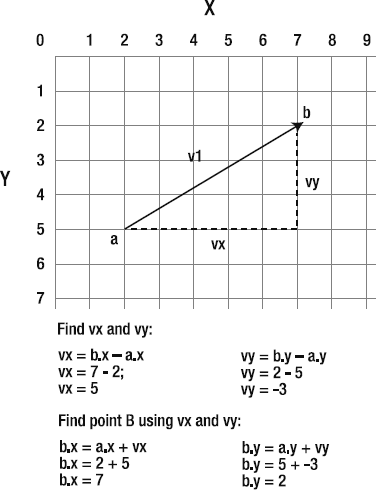
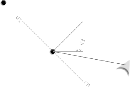
vx is known as the vector's x component. vy is the vector's y component. Figure 2-3 shows how vx and vy fit into the big picture.
You can describe any vector using vx and vy values. In fact, vx and vy values are vectors. You don't need any more information than that to use vectors effectively.
If you know where the vector starts and where it ends, you can find a vector's vx and vy values using these simple formulas:
vx = b.x – a.x;
vy = b.y – a.y;
Just subtract the start x and y points from the end x and y points.
If you know only the vector's vx and vy properties and where the vector starts, you can figure out the end point using these formulas:
b.x = a.x + vx;
b.y = a.y + vy;
Take a look at Figure 2-3 and see if you can work out how the values were found. It's pretty easy if you just take it one small step at a time.
This last set of formulas is particularly important for games, and you've probably used it many times already. Does this look familiar?
x += vx;
y += vy;
These are identical to the previous formulas. This is just another way of saying, "The new position (point B) is the same as the previous position (point A), plus velocity."
Do you see how easy all these concepts are to grasp? It's just basic math.
A very important thing to remember is that if you have vx and vy properties, you have a vector.
All vectors have a length. In geometry, a vector's length is referred to as its magnitude. Even though you might find this term confusing at first, we need to use the term magnitude so that it doesn't conflict or create confusion with the AS3.0 Array length property. Also, if you begin to get comfortable using the term magnitude now, you'll be a small step ahead when you continue learning about vectors outside the pages of this book, especially when you start to do 3D programming. Don't worry—it's not difficult! Just remember that whenever you hear me talk about magnitude, I mean the vector's length.
It's important to know what a vector's magnitude is so that you can figure out how far away things are or how fast they're moving. If a spaceship's motion vector has a magnitude of 3, then you know what its velocity is. And you can also use that information to anticipate or resolve a collision with another object, as you'll learn in the "Collision and bounce" section later in this chapter.
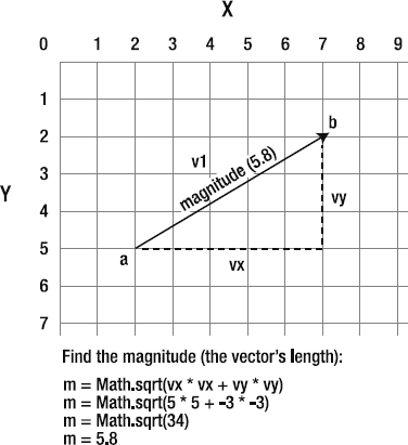
So how can we find out what a vector's magnitude is? It's the distance between point A and point B. You can easily calculate this with the help of the game designer's reliable old standby, the Pythagorean theorem.
m = Math.sqrt(vx * vx + vy * vy);
I'm using the variable name m to refer to magnitude.
Figure 2-4 illustrates how the vector's magnitude is found.
In a game, a magnitude of 5.8 could tell you how fast a spaceship is moving. Or you could use it to find out how far away the ship is from an enemy.
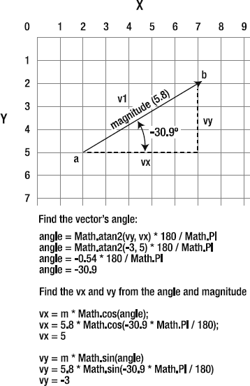
It's often useful to know a vector's angle. A bit of simple trigonometry will find it for you.
angle = Math.atan2(vy, vx) * 180 / Math.PI;
Note
With the Math.atan2 method, the y property is the first argument and the x property is the second. This is unlike every other method in AS3.0, where the x property comes first. So be careful! It's a very common mistake to put the x property first.
This formula gives you a value in degrees that you can apply to the rotation property of any object. (In the pages ahead, you'll see how this trick is used to keep text perfectly aligned to a rotating line.)
There's an interesting flip side to this. How can you find a vector if you have only its angle and magnitude (its length)? A little more trigonometry will help here as well.
vx = m * Math.cos(angle);
vy = m * Math.sin(angle);
And remember, all you need are the vx and vy properties to calculate any vector. So with these results, you're all set. With vx and vy, you still have a vector, even though it may not have a specific start or end point yet.
These formulas are the keys to being able to switch back and forth from vectors to angles and, as you will see in this chapter, they have endless utility. Figure 2-5 shows how they're used.
These two formulas are about as much trigonometry as you'll ever need to know while working with vectors. A nice little feature of the vector system is that it produces the same effects as complex trigonometry, but the math involved is much simpler, and the results are concrete and visual. If you've used trigonometry in the past to produce complex motion effects in your games, and only had a vague idea how it was working, you're going to love vectors. They're conceptually much easier to work with.
Vectors hide a deep, dark secret. Clinging to the base of each vector are two invisible and somewhat shadowy additional vectors called normals.
One of these normals runs to the left of the vector, and the other runs to its right. They are exactly perpendicular (at 90 degrees) to the main vector. Together, they form a base on which the vector stands. If you think of the vector as a rocket ship pointing up toward the sky, the left and right normals form the ground beneath the rocket. If the rocket tilts to one side, the normals will tilt along with it on the same axis. They always remain perfectly aligned at precisely 90 degrees.
That's actually how the normals got they're name. The normals define the "normal" orientation of the vector. They define the ground that the vector stands on, so you always know which way is "up" in the vector's coordinate system.
Figure 2-6 illustrates how the left and right normals connect with the main vector.
Both the left and right normals are also vectors. The left normal is a vector that points to the left, and the right normal points to the right. Whether you want to or not, every time you create a vector, you're actually creating three vectors: the main vector and its two normals. The normals have the same magnitude as the main vector. They help to define what's known as the vector's coordinate space.
It won't be at all obvious to you yet why this is important or even precisely what it means. In the pages ahead, I'll clarify the role of normals with very detailed and practical examples. What's important to be aware of right now is that the left and right normals exist and can be calculated mathematically. And they also happen to be spectacularly important in helping us figure out the angle of a collision.
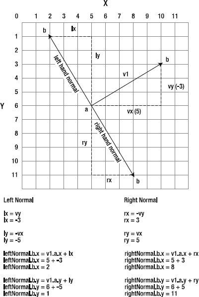
The left normal is represented by the variables lx and ly. They're very easy to calculate.
lx = vy;
ly = -vx;
As you can see, it's just a 90-degree twist on the main vector's vx and vy properties.
The right normal is found like this:
rx = -vy;
ry = vx;
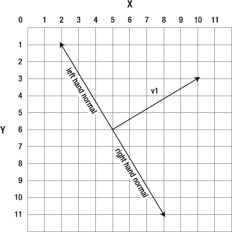
Figure 2.6. The left and right normals are perpendicular to the main vector and help define the vector's coordinate space.
Once you've found the left and right normals' lx, ly, rx, and ry values, you can easily figure out the rest of the vector information. Their start point (a) will always be the same as the main vector, so you can calculate their end points (b) like this:
leftNormal.b.x =  v1.a.x + lx;
leftNormal.b.y = v1.a.y + ly;
rightNormal.b.x =  v1.a.x + rx;
rightNormal.b.y = v1.a.y + ry;
And now you have two completely new vectors if you need them. You can apply any of the other vector calculations in this chapter to these new vectors.
It's much easier to understand all this visually, so take a look at Figure 2-7 to see how all these values are found. Keep this information close at hand, because you're going to need to use it soon.
Note
Remember that abstract calculations always correspond to real coordinates on the stage. If you ever feel confused about what a calculation does, take out a pencil and a sheet of graph paper, and break it down step by step as I've done in the diagrams here.
Did I just say "pencil" and "paper"? I did! Try it. You might find you actually enjoy that short break away from your computer.
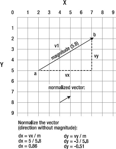
Sometimes you need to know the direction that a vector is pointing. Where is an object going? And, more important, can you use that information to orient other objects in the same direction?
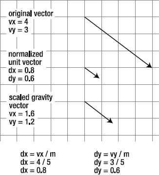
This is where the technique of normalizing a vector becomes important. Normalized vectors have a definite direction, but have their magnitude scaled to 1, which is the smallest size that a vector can be. If you first make the vector as small as possible, you can easily scale it up to any size and keep it perfectly proportioned.
Note
Don't confuse normalizing with vector normals. Very confusingly (and it is confusing!), they are two completely separate things. Normals are the vectors perpendicular to the main vector. Normalizing is a technique used to scale a vector.
Let's consider a pet story to see how a normalized vector can be useful. Your cat loves to chase squirrels, and you see some up in the tree outside your window that she might enjoy tormenting. But how can you communicate this to your cat? Your cat doesn't speak English, but thanks to studiously deciphering the numbers on the kitchen clock to calculate meal times, she has become pretty good at math. Fortunately, sitting on your desk, you have a vector that's 3 feet long and happens to be pointing up toward the tree where the squirrels are playing. The magnitude of the vector is useless to your cat. Three feet? Ha! Child's play! She can leap 20 feet in one bound. But is there some way that you can at least use the vector's direction to tell her the direction she should leap in? Yes! All you need to do is normalize the vector and give the result to your cat. That will give her the squirrels' direction, and she can scale it to 20 feet without losing its direction.
Normalized vectors are represented by the variable names dx and dy, and they are found like this:
dx = vx / m;
dy = vy / m;
You just divide the vx and vy by the vector's magnitude. The result is a really tiny vector with a length of 1. In a Flash game, it will be the size of a single pixel. Figure 2-8 illustrates how this works.
Note
Normalized vectors are also called unit vectors because their size is 1, which is the smallest possible whole unit that the vector can be. You can use unit vectors to scale a vector to any size, either larger or smaller. Have you ever wondered what the magic ingredient was in that bottle that Alice drank? It was a unit vector!
The normalized vector doesn't have any start or end points, so you can think of it as just hanging in space, waiting for someone to tell it what it should do. But most important, the numbers that result are useful for figuring out the vector's direction. If you give the dx and dy values to your cat, she'll effortlessly find the squirrels in the tree and still be back in time for lunch.
How can your cat do this? We don't know yet! As is, those dx and dy values seem pretty useless, don't they? But all shall be revealed in the pages ahead. For now, just try to understand what normalized vectors are. We'll be coming back to them again quite soon.
Note
What does the d in dx and dy mean? It stands for delta, which in mathematics is often used to show that there has been a change in a value. It's usually used to indicate that a large value has been reduced to a smaller one. By convention, dx and dy are used to represent normalized vx and vy values.
Isn't it amazing how much information you can squeeze out of just two little points? Really, at its heart, that's all we're working with: point A and point B. Whenever you have two points anywhere in your game, you can create a vector between them and access this wealth of information about the geometry of your space.
Don't worry about memorizing any of the formulas. In the next few steps, we're going to automate all of these vector calculations so that you never need to look at them again (that is, if you don't want to). However, it is important that you understand what concepts like magnitude and normalize mean. If you're not sure, spend a bit of time going through the previous section until the concepts start to click. There's no reason to rush through any of this.
The vector properties and formulas we've looked at are fundamental to what vectors are all about. In fact, they're so fundamental that you can hardly make a move in a vector universe without needing to invoke a half dozen or so of them at any time. And not only that, but you'll be using exactly the same formulas in exactly the same way, over and over again for a lot of mundane tasks. Does this seem to suggest something?
Yes, you guessed correctly! The miracle of OOP comes to our rescue again! The only sensible or manageable way to deal with vectors is to create a custom class that contains all of these properties and formulas.
Although I encourage you to create your own vector class, I've saved you the trouble by creating one for you. You'll find it here in the book's download package: com/friendsofed/vector/ VectorModel.as. VectorModel includes all of the properties and formulas we've just discussed. It allows you to create a vector object, and automatically figures out its magnitude, left and right normals, normalized dx and dy values, and angle. All those tedious calculations that you'll no longer need to worry about.
If you hadn't already guessed, the VectorModel class is a model in an MVC system. It comes with a corresponding VectorView class that visually displays the vector on the stage if you need to see it.
Let's take a look at how to use these classes to build and test the vectors you use in your games.
To create a VectorModel object, import the class and instantiate it like this:
private var _v1:VectorModel = new VectorModel(a.x, a.y, b.x, b.y);
The arguments are the x and y positions of the vector's start and end points. These arguments are actually optional, because you can add the start and end points later with the class's update method. We'll take a close look at how to do this ahead. But it means you can also create a VectorModel object without any arguments, like this:
private var _v1:VectorModel = new VectorModel();
You can also create a VectorModel without start and end points, as long as you know the vx and vy values.
private var _v1:VectorModel = new VectorModel(0,0,0,0, vx, vy);
Assign 0 (zero) for the start and end points, and add the vx and vy values as the last arguments.
The following is the complete VectorModel class. It's long, but most of its bulk is due to extra checks that need to be made to find out whether the vector has start and end points or just vx and vy values.
package com.friendsofed.vector
{
  import flash.geom.Point;
  import flash.events.Event;
  import flash.events.EventDispatcher;

  public class VectorModel extends EventDispatcher
  {
    //Start and end points for the main vector
    private var _a:Point = new Point(0, 0);
    private var _b:Point = new Point(0, 0);
    private var _vx:Number = 0;
    private var _vy:Number = 0;

    public function VectorModel
      (
        startX:Number = 0, startY:Number = 0,
        endx:Number = 0, endy:Number = 0,
        newVx:Number = 0,
        newVy:Number = 0
      ):void
    {
      update(startX, startY, endx, endy, newVx, newVy);
    }

    public function update
      (
        startX:Number = 0,
        startY:Number = 0,
        endx:Number = 0,
        endy:Number = 0,
        newVx:Number = 0,
        newVy:Number = 0
      ):void
    {
      if(newVx == 0 && newVy == 0)
      {
         _a.x = startX
_a.y = startY;
_b.x = endx
_b.y = endy;
dispatchEvent(new Event(Event.CHANGE));
}
else
{
_vx = newVx;
_vy = newVy;
dispatchEvent(new Event(Event.CHANGE));
}
}
//Start point
public function get a():Point
{
return _a;
}
//End point
public function get b():Point
{
return _b;
}
//vx
public function get vx():Number
{
if(_vx == 0)
{
return _b.x - _a.x;
}
else
{
return _vx;
}
}
//vy
public function get vy():Number
{
if(_vy == 0)
{
return _b.y - _a.y;
}else
{
return _vy;
}
}
//angle (degrees)
public function get angle():Number
{
var angle_Radians:Number = Math.atan2(vy, vx);
var angle_Degrees:Number = angle_Radians * 180 / Math.PI;
return angle_Degrees;
}
//magnitude (length)
public function get m():Number
{
if(vx != 0 || vy != 0)
{
var magnitude:Number = Math.sqrt(vx * vx + vy * vy);
return magnitude;
}
else
{
return 0.001;
}
}
//Left normal VectorModel object
public function get ln():VectorModel
{
var leftNormal:VectorModel = new VectorModel();
if(_vx == 0
&& _vy == 0)
{
leftNormal.update
(
a.x, a.y,
(a.x + this.lx),
(a.y + this.ly)
);
}
else
{
leftNormal.update(0, 0, 0, 0, vx, vy);
}return leftNormal;
}
//Right normal VectorModel object
public function get rn():VectorModel
{
var rightNormal:VectorModel = new VectorModel();
if(_vx == 0
&& _vy == 0)
{
rightNormal.update
(
a.x, a.y,
(a.x + this.rx),
(a.y + this.ry)
);
}
else
{
rightNormal.update(0, 0, 0, 0, vx, vy);
}
return rightNormal;
}
//Right normal x component
public function get rx():Number
{
var rx:Number = -vy;
return rx
}
//Right normal y component
public function get ry():Number
{
var ry:Number = vx;
return ry;
}
//Left normal x component
public function get lx():Number
{
var lx:Number = vy;
return lx
}//Left normal y componentpublic function get ly():Number { var ly:Number = -vx; return ly; }//Normalized vector//The code needs to make sure that//the magnitude isn't zero to avoid//returning NaNpublic function get dx():Number { if(m != 0) { var dx:Number = vx / m return dx; } else { return 0.001; } } public function get dy():Number { if(m != 0) { var dy:Number = vy / m return dy; } else { return 0.001; } } } }
As you can see, the VectorModel class just codifies all the vector properties and calculations that we looked at earlier in this chapter. It also has an update method that dispatches a CHANGE event. This is important because it means we can use this model to create a custom view of its data.
One important detail is that the dx and dy getters need to check to make sure that the vector's magnitude isn't zero. Whenever there is a chance—even an extremely improbable chance—that a variable used in a division calculation might evaluate as zero, you should check for this and provide an alternative. Instead of zero, dx and dy return 0.001, which is small enough to have the actual effect of zero in the applications where we'll be using it.
Division by zero will result in the code returning NaN (which stands for Not A Number). This could completely break the code in your game, and you wouldn't know division by zero was the cause unless you were tracing the values.
A feature of the VectorModel class is that it creates two subobjects, ln and rn, which are the left and right normals. Here's how the left-hand vector object is created.
public function get ln():VectorModel
{

  var leftNormal:VectorModel = new VectorModel();

  if(_vx == 0
  && _vy == 0)
  {
    leftNormal.update
      (
        a.x, a.y,
        (a.x + this.lx),
        (a.y + this.ly)
      );
  }
  else
  {
    leftNormal.update(0,0,0,0, vx, vy);
  }

  return leftNormal;
}
Are you following this?
First, it checks to see whether the vector has start and end points, or whether it just has vx and vy values. It creates the vector with different values in the constructor arguments based on that.
But what's really interesting is how it's creating the vector. It's actually creating a new instance of the very same class that it's a part of!
var leftNormal:VectorModel = new VectorModel();
This directive is in the VectorModelclass itself. Pretty cool, huh? It may seem sort of crazy, but it's a perfectly legitimate thing to do in AS3.0, and in this case, it's extremely useful. It means that every time you create a VectorModel object, you're actually creating three VectorModel objects: one for the main vector and one each for the left and right normals.
If your main vector is called _v1, you can access its left and right normal vectors like this:
_v1.ln
_v1.rn
And because ln and rn are themselves VectorModel objects, they contain all of the same properties as the parent object. For example, to find the end point of the left normal, you could write some code that looks like this:
_v1.ln.b
To find the right normal's angle, you could use this:
_v1.rn.angle
Thank you, OOP!
Once you've created a VectorModel, you can display it with the VectorView class. Here's how:
private var _v1:VectorModel = new VectorModel();
private var _v1View:VectorView = new VectorView(_v1, "status", 1);
The VectorView class takes three arguments:
The
VectorModelobjectA
String, which is the type of display you would like. This can be one of the following:basicdisplays a single straight line between the vector's start and end points.detaileddisplays the main vector, itsvxandvy, and the left and right normals.statusincludes a status box that displays all of the vector's data.
A number, which is the vector's scale. If you don't want to scale the vector, leave it at 1 (which is its default value).
We'll look at examples of how to customize the view using these three arguments in the examples ahead.
Feel free to examine the VectorView class, but it's really just a utility to help you view VectorModel objects. It's pretty complex, so I won't go into detail about it here. I've commented most of the code if you're curious as to how it works. Except for a few small details, there's nothing new there that you haven't seen before in other contexts.
OK, I know I've been taking my time getting here, but it's worth the wait. With all the pieces now together, we can plot and display vectors on the stage.
In the chapter's source files, you'll find a folder called VectorBasics. Run the SWF, and you'll see something that looks like Figure 2-9. You can fly the spaceship around the screen using the cursor keys, and the program draws a vector between the center of the stage and the ship's x and y position. It also plots the vx and vy, plots the left and right normals, and displays the VectorModel's data in a status box.

Take a bit of time with this and see if you can connect the dots in your own mind as to how the lines you see on the stage relate to the vector's data. It's all the theory that we've covered so far, but now it's interactive and visual.
Here's the VectorBasics application class that makes all this happen:
package
{
  import flash.events.Event;
  import flash.display.Sprite;
  import com.friendsofed.utils.*;
  import com.friendsofed.gameElements.spaceShip.*;
  import com.friendsofed.vector.*;
[SWF(backgroundColor="0xFFFFFF", frameRate="60",
width="550", height="400")]
public class VectorBasics extends Sprite
{
//The spaceship
private var _shipModel:ShipModel
= new ShipModel();
private var _shipController:ShipController
= new ShipController(_shipModel);
private var _shipView:ShipView
= new ShipView(_shipModel, _shipController);
//The vector
private var _v1:VectorModel = new VectorModel();
private var _v1View:VectorView = new VectorView(_v1, "status", 1);
public function VectorBasics()
{
//Add the ship view and set the ship model position
addChild(_shipView);
_shipModel.setX = 275;
_shipModel.setY = 200;
//Add the vector view
addChild(_v1View);
addEventListener(Event.ENTER_FRAME, enterFrameHandler);
}
private function enterFrameHandler(event:Event):void
{
//Update the ship model
_shipModel.update();
StageBoundaries.wrap(_shipModel, stage);
//Update the vector model
_v1.update(275, 200, _shipModel.xPos, _shipModel.yPos);
}
}
}Let's look at some interesting details of this program a bit more closely.
Note
Notice that the model and view objects were both declared and instantiated in the class definition.
private var _shipModel:ShipModel = new ShipModel();
In Chapter 1, this was broken into two steps. First, the variable was declared:
private var _shipModel:ShipModel;
and then it was instantiated in the class constructor:
_shipModel = new ShipModel();
Adobe recommends that if you need to initialize a property to a default value, you do this at the same time as you declare it. Except for a few places where this might obscure clarity, the code will follow this convention throughout the rest of the book.
The VectorModel's update method is called each frame.
_v1.update(275, 200, _shipModel.xPos, _shipModel.yPos);
The arguments are the x and y positions of the vector's start and end points.
Note
In your own projects, you might want to modify this system so that the vector model is automatically updated based on changes to the ship model. This would not be hard to implement, but to keep this code as flexible and clear as possible, I've opted to update it manually each frame. It helps to expose very clearly what is going on behind the scenes.
When the vector model updates, its CHANGE event is fired, and the view redraws the vectors on the stage. How does it do that?
In Chapter 1, we looked at how you can use the drawing API to draw lines and shapes on the stage. If you want those lines and shapes to change every frame, you need to use the graphics.clear method. The graphics.clear method erases the drawing from the previous frame and redraws the line or shape with the new updated coordinates. To use it, just call it as the first drawing method. This example from the VectorView class draws the main vector line:
_mainVector.graphics.clear();
_mainVector.graphics.lineStyle(1, 0xFF0000, 1);
_mainVector.graphics.moveTo(_startX, _startY);
_mainVector.graphics.lineTo(_endX, _endY);
Without clearing the graphics each frame, the previous line will stay on the stage, and the new line will be drawn over it. Figure 2-10 shows what the VectorBasics SWF would look like if it were compiled without the graphics.clear method in the preceding code. In many cases, this actually might be a desirable effect.
You might be wondering what specific code makes all the lines rotate. Surprisingly, the answer is nothing at all. The appearance of the lines rotating is simply a result of the vector's data being displayed. A new line is just being drawn between the vectors' start and end points each frame. Nothing has been done to the original VectorModel data; it's just being displayed on the stage, as is. Rotation is a by-product. That's the great thing about using a vector system: You can achieve effects that are identical to complex trigonometry, but there's not a cos, sin, or atan in sight!
Note
Sometimes you will have sprites or movie clips in your games that aren't using vectors. A nonvector object might need to know how a vector is aligned so that it can update its rotation property to match the vector's orientation. In those cases, use the VectorModel's angle property to tell the Sprite or MovieClip object how to align.
You'll notice that the text used to label the left and right normals (ln and rn) rotates in precise alignment with them, as illustrated by Figure 2-11. How is this accomplished?
The label text is a custom RotationText object, which extends the Sprite class. You'll find the RotationText class in the com/friendsofed/utils folder. Its main job is to wrap text in a Sprite container so that it can make use of the Sprite's rotation property. To rotate a RotationText object, all you need to do is find the vector's angle and assign it to the rotation property. For more information about the RotationText class, see the "A crash course in embedding assets" section later in this chapter.
Remember that the VectorModel has an angle property. Also remember that the left and right normals (ln and rn) are VectorModel objects as well, so they have an angle property, too. It's therefore the simplest thing in the world to assign this value to the text's rotation property:
_rn_Label.rotation = _v1.rn.angle;
_ln_Label.rotation = _v1.ln.angle;
That's all there is to it! The text rotates in precise alignment with the vectors. You could use exactly the same technique to align the rotation of any Sprite or MovieClip object.
Note
Before you can rotate text, make sure that you're using an embedded font. The "A crash course in embedding assets" section later in this chapter explains how to embed fonts and images directly into your AS class files.
The final new technique in the VectorBasics application class we'll look at is how to round numbers to a specific number of decimal places.
You'll notice that the numbers displayed in the status box have all been rounded to three decimal places. I rounded the numbers in the VectorView class so that they would be easier to read. Otherwise, most of them would have 16 trailing decimal places and would be a big blur of information that would be difficult to absorb. Figure 2-12 compares the rounded values to the raw values—which would you prefer to look at?
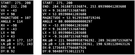
The numbers were rounded to three decimal places using AS3.0's built-in Math.round method, like this:
Math.round(_vx * 1000) / 1000;
In some debugging situations, you might need the detail of raw data. In those cases, just remove Math.round from the VectorView class.
To increase the number of decimal places, just add more zeros to 1000. Easy stuff!
Note
There may be some cases where you want a number to be rounded to one decimal place, but still display a trailing zero, such as 4.30 or 56.80. The trailing zero is mathematically meaningless to AS3.0, so the compiler always truncates it. For display purposes, however, you might sometimes need it. You can use the toFixed method to achieve this. For example, the following rounds 4.3457894 and displays it as 4.30:
var number:Number = 4.3457894;
var roundedNumber:Number = Math.round(number * 10 ) / 10;
trace(roundedNumber.toFixed(2));
The number that toFixed returns is actually a String, so it can be used only for display.
The VectorBasics example file is intended to show you how to use the VectorModel and VectorView classes to help you visualize vectors. Don't let all the extra code confuse you! At it heart lies the very simple calculations we looked at earlier in the chapter. If you understand its basic vector concepts and calculations, that's all you need to know.
The VectorModel class helps automate these calculations so that you don't need to worry about them. You're free to concentrate on making creative games. But you don't have to use the VectorModel class. If you prefer, you can just use the basic calculations as is, without building a class around them.
You can think of vectors as forces. A vector with a magnitude of 5 is a force that makes your spaceship move 5 pixels each frame. Sometimes in a game, you'll have more than one force acting on an object. Maybe the force of gravity is pulling your spaceship down, and wind is pushing it to the right. You can create vectors for gravity and wind, and then add or subtract those vectors to your ship's motion vector to find the ship's new direction.
Let's take gravity as an example. Imagine that your ship's motion vector has a magnitude of 5, and in your game, you have a gravity vector with a magnitude of 2. If gravity is acting on your spaceship, you want to subtract 2 from 5 to find the ship's new motion vector, which will be 3.
Subtracting the magnitudes of vectors isn't useful in most cases, because the magnitude alone doesn't tell you the vector's direction. Instead, you need to subtract the vector's vx and vy values in two separate calculations. This is incredibly easy to do.
As an example, imagine that you have a spaceship hovering above a flat planet surface. The force of gravity on the y axis is pulling the ship down. If the force of gravity is 2, you can describe its vx and vy properties like this:
gravity_Vx = 0;
gravity_Vy = 2;
Don't forget that in Flash's backward coordinate system, gravity will have a positive value, so you'll need to add it to you ship's motion vector to pull the ship downward.
Remember that if you have a vx and a vy value, you have a vector. It might not have start or end points, but it's still a vector. In this case, the gravity acts only on the y axis, so you don't need a value for vx.
Here's how you can add the force of gravity to the ship's motion vector:
shipModel.vy += gravity_Vy;
If the ship started with a vy of −5, its new value would now be −3. This would pull the ship down in the next frame. Figures 2-13 and 2-14 illustrate how this vector addition works.
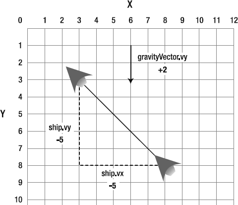
Figure 2.13. What happens when you combine a gravity vector and the ship's motion vector? In this example, the ship's vy value is −5, and the gravity vector is +2.
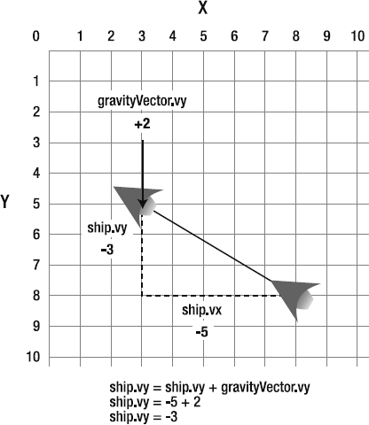
Figure 2.14. When the two vectors are added together, a new vector results, which combines their forces. This pulls the ship down toward the planet surface.
When you add vectors together like this, the result is a new vector. It's a combination of the downward pull of gravity and the upward push of the ship. As you can see, the math is amazingly simple, but it's a very accurate description of what happens in the real world.
You've probably used this same kind of vector addition in many of your own games, but never realized the mechanics behind it. It's a pretty easy concept to grasp, especially if you visualize it like this. Don't forget how this simple example works, because even the most complex combination of forces uses these exact same mechanics.
Next, we'll look at a more complex example.
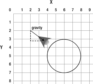
In our simple gravity example, the ship was pulled down on the y axis. This is fine in a platform or pinball game, where "down" is the bottom of the stage. But suppose your spaceship is circling a planet? Which way is down? Take a look at Figure 2-15 and see if you can figure it out.
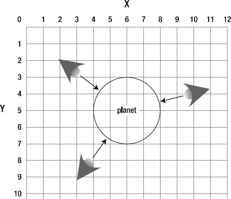
Looking at that diagram, two things should come to mind.
The ship needs to know where the center of the planet is.
To move the ship toward the planet's center, gravity must act on the both the x and y axes.
Here are the steps to figuring out the force of gravity for a round planet.
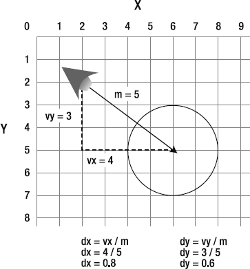
Create a vector between the ship and the center of the planet. This provides the ever-useful
vxandvyvalues, which are going to help us in the next step.The magnitude of the vector is actually useless to us. We don't need to know the distance between the ship and planet. However, we do need to know the vector's direction.
Does that ring a bell? It should. Whenever you need a vector's direction but not its magnitude, you normalize the vector. That means reducing it to its smallest possible size. A normalized vector, or unit vector, is represented by the variables
dxanddy. To find those values, dividevxandvyby the vector's magnitude.Figure 2-16 shows how to calculate the
dxanddyfrom the ship-to-planet vector.We can use the unit vector to create a new gravity vector. How strong do you want gravity to be? For most games, you'll want it to be about half to a tenth of the value of
dxanddyfor a realistic effect. In this example, let's scale the gravity vector to 2, so that you can see the effect more clearly.gravity_Vx = dx * 2 gravity_Vy = dy * 2
Now we have a gravity vector, working in both the x and y axes, that's pointing directly toward the center of the planet. The direction is the same as the original vector, but the magnitude is different.
Figure 2-17 shows how the original vector was scaled and the new gravity vector derived.
Finally, we can apply the gravity vector to the ship's motion vector.
ship.vx += gravity_Vx
ship.vy += gravity_Vy
The ship will very naturally be drawn toward the center of the planet, no matter which side of the planet it's on. Figure 2-18 shows how the position of the ship is influenced by this new gravity vector. Compare it to Figure 2-15 to see the difference.
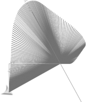
If you understand all these concepts, putting them into practice is almost trivial. In the chapter's source files, you'll find a folder called AddingVectors. Run the SWF and fly the ship around the planet. Gravity will gradually pull the ship towards the center. If you let it run for a while, the ship will gradually fall into a perfect orbit. Figure 2-19 shows what you'll see. There's no collision detection with the planet in this example, but that would not be difficult to implement.
The vector that you can see on the stage is the vector between the planet and the ship. The status box on the left gives detailed information about that vector.
The status box on the right is the gravity vector. The gravity vector has only vx and vy properties, so its start and end points are zero. However its angle, dx, and dy exactly match that of the ship-to-planet vector.
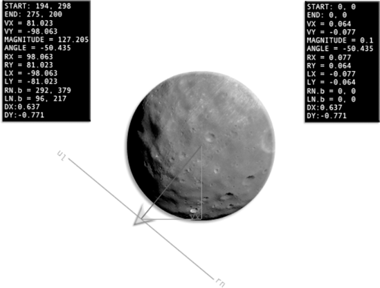
Figure 2.19. The gravity vector is added to the ship's motion vector, which gradually pulls the ship to the center of the planet.
How big is the gravity vector? The status box shows that its m (magnitude) property is 0.1. It has been scaled to one-tenth the size of the normalized vector, which is really, really small. It's so small that it's impossible to plot visibly on the stage. But it's this amount that is nibbling away at the spaceship's velocity each frame and causing it to move toward the center of the planet.
Let's take a look at the code that makes this happen, and I'll explain some of the specifics.
package
{
  import flash.events.Event;
  import flash.display.Sprite;
  import com.friendsofed.utils.*;
  import com.friendsofed.gameElements.spaceShip.*;
  import com.friendsofed.vector.*;
  import planet.Planet;

  [SWF(backgroundColor="0xFFFFFF", frameRate="30",
  width="550", height="400")]

  public class AddingVectors extends Sprite
  {
    private var _shipModel:ShipModel
      = new ShipModel();
    private var _shipController:ShipController
      = new ShipController(_shipModel);

    private var _shipView:ShipView
      = new ShipView(_shipModel, _shipController);

    //Ship-to-planet vector
    private var _v1:VectorModel = new VectorModel();
    private var _v1View:VectorView = new VectorView(_v1, "status", 1);

    //Gravity vector
    private var _gravityVector:VectorModel
      = new VectorModel();
    private var _gravityVectorView:VectorView
      = new VectorView(_gravityVector, "status", 1);

    //Planet
    private var _planet:Planet = new Planet(100, 0x999999, 280);

    public function AddingVectors()
    {
      //Add the planet
      addChild(_planet);
      _planet.x = stage.stageWidth / 2;
      _planet.y = stage.stageHeight / 2;
//Add the shipaddChild(_shipView); _shipModel.setX = 100; _shipModel.setY = 200;//Add the vector viewsaddChild(_v1View); addChild(_gravityVectorView); _gravityVectorView.x = 450;//Set ship's friction to 1 (no friction) for realistic orbiting effect_shipModel.frictionConstant = 1; addEventListener(Event.ENTER_FRAME,enterFrameHandler); } private function enterFrameHandler(event:Event):void {//Update the ship model_shipModel.update(); StageBoundaries.wrap(_shipModel, stage);//Update the ship-to-planet VectorModel_v1.update ( _shipModel.xPos, _shipModel.yPos, _planet.x, _planet.y );//Calculate gravity//Use the normalized vector to create a new//vector with a new magnitude.//This new vector will be the "force of gravity"//that we can add to the ship's existing vx and vy vectorvar gravity_Vx:Number = _v1.dx * 0.1; var gravity_Vy:Number = _v1.dy * 0.1;//Update the gravity vector model_gravityVector.update(0,0,0,0, gravity_Vx, gravity_Vy);//Trace the gravity vector's magnitude to check its sizetrace(_gravityVector.m);//Add the gravity vector to the ship's motion vector_shipModel.vx += _gravityVector.vx; _shipModel.vy += _gravityVector.vy; } } }
A glance at this code should tell you that 90% of it is routine. The gravity magic happens in the last few lines.
Note
A small technical detail that the code needs to take care of is to remove the effect of friction on the spaceship by setting its frictionConstant property to 1.
_shipModel.frictionConstant = 1;
This is important so that friction doesn't slow down the ship and obscure the orbiting effect. The ShipModel initializes friction to 0.98, which will gradually cause the ship to slow. Setting it to 1 overrides the initial setting and allows the spaceship to orbit without any inertia, as it would in deep space.
If you're wondering how the planet was created, flip ahead to the "A crash course in embedding assets" section later in this chapter.
Here are the steps for making the gravity work:
Create a vector between the ship and the planet. This is important, because from it we can derive the direction on which gravity needs to act on the ship.
_v1.update
  (
    _shipModel.xPos,
    _shipModel.yPos,
    _planet.x,
    _planet.y
  );
This vector,
_v1, is updated in anENTER_FRAMEloop, so its start and end points are always changing. It's this vector that is plotted on the stage.Create the gravity
vxandvyusing_v1'sdxanddyproperties. They're multiplied by 0.1 to create a really small vector. A larger number will increase the force of gravity, and a smaller number will weaken it.var gravity_Vx:Number = _v1.dx * 0.1; var gravity_Vy:Number = _v1.dy * 0.1;
Use
gravity_Vxandgravity_Vyto update thegravityVector VectorModelobject._gravityVector.update(0,0,0,0, gravity_Vx, gravity_Vy);
This is actually an optional step. Really, all you need are the
gravity_Vxandgravity_Vyvalues from step 2. I decided to create a gravityVectorModelobject in this code for two reasons:I want to show you how you can make a
VectorModelobject using onlyvxandvyvalues. You don't need start or end values to make a vector. It also underlines that, yes, gravity is a real-live vector, just like any other vector. It just happens to be too small to see on the stage.It easily allows you to display the vector's data using a
VectorView.Note
If performance is an issue, you probably shouldn't create a whole
VectorModelobject around these values because it could add unnecessary overhead to your game. You'll need to test this on a case-by-case basis, but you may find that your game runs faster if you manually calculate vector properties as you need them. If so, use the formulas that we looked at earlier in this chapter, and calculate the values only when and if they're used in the game. There's no point weighing down your game with extra code that you don't use. For learning and testing purposes however, creatingVectorModelobjects is pretty useful because they can help you visualize and diagnose tricky design problems, as well as save you from needing to write reams of repetitive code.
Finally, combine the ship's motion vector and the gravity vector.
_shipModel.vx += _gravityVector.vx;
_shipModel.vy += _gravityVector.vy;
These are very small values, but over time, they compound for a very noticeable effect on the stage gravity!
As I mentioned before, you could instead use the
gravityVxandgravityVyvalues directly, like this:_shipModel.vx += gravity_Vx; _shipModel.vy += gravity_Vy;
When I first started learning game design, I would wonder in amazement at examples like this. Certainly the minimum requirement for writing code like this must be an advanced degree in astrophysics and maybe a minor in metaphysics. When I eventually built up the courage to start researching it, I was surprised to discover, "Hey, it's just basic math!" Addition, subtraction, multiplication, and division are all it takes to make the world—or even an entire solar system—go round. Makes you think!
There's one small problem with our spaceship example that you may have noticed. The force of gravity is the same no matter how far away the ship is from the planet. In space, the force of gravity between objects weakens as they move further apart. Also, large objects with a lot of mass will have a greater gravitational attraction than smaller objects. We can implement a more realistic gravitational system with just a bit more tweaking.
First, create some variables that represent the mass of the planet and the spaceship. The values you use will depend on trial and error, but the following values work well in this example:
var planetMass:Number = 5;
var shipMass:Number = 1;
Next, replace the directives that calculate the gravity vx and vy with these new directives:
var gravity_Vx:Number = _v1.dx * (planetMass * shipMass) / _v1.m;
var gravity_Vy:Number = _v1.dy * (planetMass * shipMass) / _v1.m;
Recompile the SWF with this code, and you'll notice that the gravity is weaker when the ship moves farther away from the planet. If you now watch the gravity vector's m property, you'll notice that it's no longer just static at 0.1. It becomes smaller when the ship moves farther from the planet and larger when it approaches it.
0.123
0.116
0.109
0.103
0.097
0.091
If you add a few more planets with different masses and initial velocities, you could use this to create a complex, gravity-based space exploration game with realistic physics. Start building your own universe!
Remember the left and right normals? They are those mysterious secondary vectors that form the base of every vector. They always exist, as mathematical entities, whether you want them to be there or not. But what are they good for? Let's take a closer look at some of the properties of normals and how to put them to some useful work in a game.
Here's a fact: the left normal will always be to the left of the main vector, and the right normal will always be to the right.
Oh, you don't believe me? How can that be true if very often the right normal appears on the left side of the stage, and the left normal appears on the right side of the stage, as in Figure 2-20?
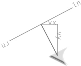
Figure 2.20. The left normal is on the right, and the right normal is on the left. The curious case of the not-so-normal normals!
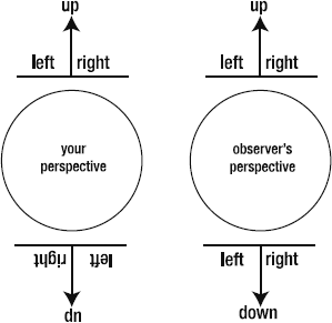
To understand how this works, imagine that you're standing on the North Pole. Your head is pointing up toward the sky. To your left is your left arm; to your right is your right arm. But hey, the North Pole is freezing cold, so maybe it will be a little warmer on the other side of the planet?
After a long walk, you finally end up on the South Pole, which to your great disappointment is even colder than the North Pole! But still, after all of the adventure getting there, you're happy just to still be in one piece. To make sure, you check: yes, your left arm is still to your left and your right arm is still to your right. Your head is still firmly connected to your body, and it is still pointing up toward the sky.
But how can that be? If you think about it, on the South Pole, your left and right have actually become reversed, and your head is pointing down, not up. Figure 2-21 illustrates this conundrum. At least, that's what it would look like to an objective observer watching your antics from the moon.
From your point of view, however, nothing has changed. You have your own coordinate system, which is separate from the coordinate system of the world around you. Up is always up, and left and right are always left and right, no matter on which side of the planet you're standing.
Vectors work in the same way. No matter how they're oriented, the main vector will always be pointing up, and the left and right normals will always be to the left and right of it, at exactly 90 degrees. This is the vector's own coordinate system.
In your games, vectors often will need to share information about their orientation and coordinate system. The classic problem—and the one we're going to solve by the end of this chapter—is an object bouncing off an angled surface. The bouncing object creates a vector when it moves, and the angled surface is another vector. To find the correct angle that the object should bounce away, you need to project one vector's coordinate system onto the other. The resulting compromise between coordinate systems will produce a new vector that will become the bouncing object's new velocity.
Again, it's "basic math," as I like to say. But there are a few little bumps along the road that we have to navigate around to get there. The first, is finding out whether two vectors are pointing in the same direction.
You can mix, match, add, and multiply vectors as much as you like, and all kinds of interesting numbers are produced as a result. One of these numbers is called the dot product. You can use it to find out whether two vectors are pointing in the same direction or in opposite directions.
Imagine you have the two vectors _v1 and _v2. You can find their dot product like this:
dotProduct = _v1.vx * _v2.dx + _v1.vy * _v2.dy
If the dot product is positive, the vectors are pointing in the same direction. This rather quaint but otherwise useless seeming bit of information can actually give a very powerful description of where your game objects are in the relation to each other.
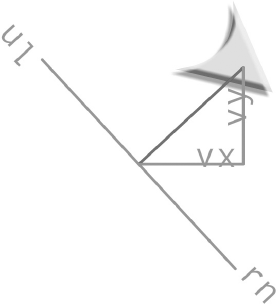
A live example is the best way to see how this works. In the chapter's source files, find the folder called DotProduct and run the SWF. You'll see a vector that has been plotted between two circles, which you can drag around the stage with the mouse. Dragging the circles changes the magnitude and orientation of the vector. You'll also see the spaceship's motion vector, extending from the center of the ship, which has been scaled to ten times its original size. A status box tells you whether the vectors are pointing in the same direction.
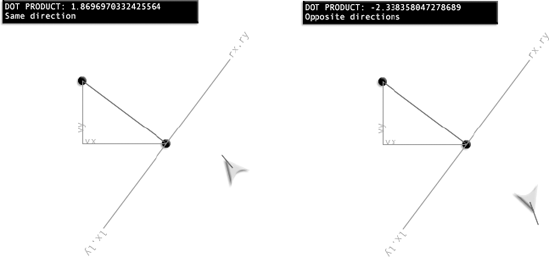
You'll notice that when the vectors are pointing in the same direction, the dot product is positive. Even if you drag the circles around to change the orientation of the vector, the dot product will always be able to tell you "which way is up." It might seem like a small detail, but the dot product is the key to synchronizing the coordinate systems of two vectors.
Much of the code is similar to the previous examples, and you can see all the specifics in the source file. Here, we'll take a quick look at the new things.
The draggable circles are DragHandle objects. You'll find the DragHandle class in the com.firendsofed.utils package. They're useful for testing, and you can create them like this:
var dragHandle = new DragHandle();
With two DragHandle objects on the stage, it's very easy to create a vector between them. Just create a VectorModel object for the vector between them, like so:
private var _v2:VectorModel = new VectorModel();
Then update the VectorModel in the enterFrameHandler:
_v2.update(_handle1.x, _handle1.y, _handle2.x, _handle2.y);
The spaceship's motion vector was scaled by 10 so that it's easy to see on the stage. That red line extending from the center of the ship points in the direction that the ship is traveling. Scaling very small vectors like this is also something that's useful while you're testing, because it's quite difficult to see a vector that's only a few pixels long. You can scale a vector by providing a number either greater or smaller than 1 as the third argument in the VectorView constructor.
private var _v1View:VectorView = new VectorView(_v1, "basic", 10);
The scaling affects only the VectorView. The VectorModel contains the original unchanged vector.
The spaceship's motion vector is represented by only vx and vy properties. It's one of those "hanging in space" vectors, like gravity, that doesn't have start and end points. So that you can actually see it on the stage, you need to give it a definite start point and calculate the end point. You can use the spaceship's x and y position as a start point.
_v1.update
  (
    _shipModel.xPos, _shipModel.yPos,
    (_shipModel.xPos + _shipModel.vx),
    (_shipModel.yPos + _shipModel.vy)
  );
The vector's end point is calculated by adding the vx and vy properties to the ship's x position.
The com.friendsofed.vector package contains a custom class called VectorMath. This class has some static methods that can be used for common vector math calculations. The VectorMath.dotProduct method finds the dot product of two vectors, like this:
var dotProduct:Number = VectorMath.dotProduct(_v1, _v2);
You can reverse the _v1 and _v2 arguments and, even though the actual number returned will be different, it will still be positive only when the vectors are pointing in the same direction.
The VectorMath.dotProduct method looks like this:
static public function dotProduct(v1:VectorModel, v2:VectorModel):Number
{
   var dotProduct:Number =  v1.vx *  v2.dx + v1.vy * v2.dy;
   return dotProduct;
}
Although you may already see some uses for calculating a dot product in a game, it really comes into its own when used as the basis for projecting a vector onto another vector.
Note
The formula I'm using to calculate the dot product in this book is scaled to the magnitude of the first vector (v1 in this example):
dotProduct = v1.vx * v2.dx + v1.vy * v2.dy
The first vector is multiplied by the second vector's normalized unit vector. This gives you a very useful number that you can use to help resolve collisions (among other things). However, it's not the standard formula for calculating the dot product. Here's the textbook formula:
dotProduct = v1.vx * v2.vx + v1.vy * v2.vy
This version doesn't use v2's dx value. Instead, it uses the vx value of v2. This produces a number that isn't scaled. Again, this formula isn't used in this book.
Projection is when you overlay a vector onto another vector's coordinate system. It's a slightly tricky concept to grasp when you first start working with it, so let's first look at a simple analogy.
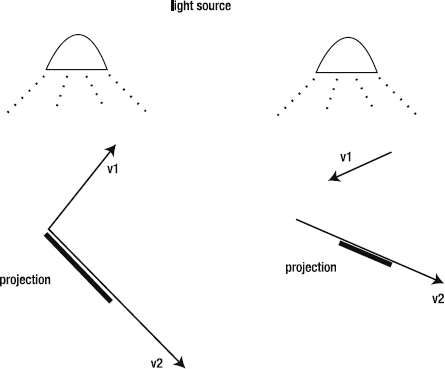
Imagine that you're standing on the sidewalk. It's a sunny day, and the sun is behind you casting your shadow on the concrete. Your shadow is the projection of you onto the sidewalk. If you think of yourself as a vector, and the sidewalk as another vector, your shadow is a third vector. It has a lot of your qualities, but conforms to the sidewalk's coordinate system.
That's all a projection is: the vector's shadow on another vector. Figure 2-23 shows two examples of v1 projected onto v2. The projection itself becomes a new vector.
A live example is the best way to see projection at work. In the chapter's source files, you'll find a folder called ProjectingVectors. Run the SWF and fly the ship around the stage. Now let's explore how it works.
The program uses three vectors:
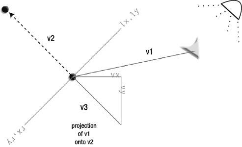
v1is the vector between the ship and the right drag handle.v2is the vector between the two drag handles.v3is a new vector that is a projection ofv1ontov2. This isv1's shadow onv2.
To reduce the clutter on the stage, I haven't added a view for v2, the vector between the drag handles. Just imagine a line drawn between those points. The view for v1 is basic, displaying only the vector and not its normals. v3, the projected vector, is displayed with its vx, vy, and normals. To help you make sense of what's happening here, take a look at Figure 2-24, which shows all the vectors at work in this example. Keep this diagram at hand when you're referring to the source file or SWF, so you understand which vectors are which.
To get a clear understanding of how this example works, open the SWF and fly the ship around a bit for yourself, as in Figure 2-25. v3 is the projection of v1 onto v2. Flying the ship around changes v1. v3 tries to match that change, but it's constrained by v2's coordinate system. Imagine an invisible light following the ship around casting a shadow of v1 onto v2. v3 is that shadow.
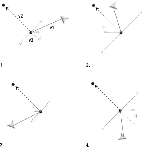
Figure 2.25. The projected vector tries the match both dimensions of the original but is trapped in one dimension. The result is a one-dimensional compromise between the original vector's vx and vy.
The math to project v1 onto v2 in this example is simple. First, find the dot product of v1 and v2:
var dotProduct:Number = VectorMath.dotProduct(_v1, _v2);
The projection is a new vector. As you know by now, if you have a vx value and a vy value, you have a vector. So the next step is to multiply the dot product by v2's dx and dy to find the projected vector:
var projection_Vx:Number = dotProduct * _v2.dx;
var projection_Vy:Number = dotProduct * _v2.dy;
And that's it, You have your projected vector!
The example file goes one step further and uses the projection's vx and vy values to create a VectorModel object. This is purely for display purposes, so it's necessary only if you want to see the projected vector on the stage or need some of its additional properties, such as its magnitude or angle.
_v3.update
  (
    _handle1.x,
    _handle1.y,
    (_handle1.x + projectedVx),
    (_handle1.y + projectedVy)
  );
Again, the math is simple. But the concept is a little tricky to grasp, so don't rush ahead until you feel you have a grip on it. Understanding projection is crucial to being able to make objects bounce off angled surfaces.
Now you know that you can cast a shadow of a vector onto any other vector. A vector's shadow is called a projection. The projection is itself a new vector.
Remember that a vector's normals are also vectors. That means that you can project a vector onto another vector's left or right normal. Why would you want to do this? Because the dot product that results can tell you exactly on which side of the vector another object is. This is important because it means you can use a vector to create an environmental boundary—that is, a solid surface that things can bounce off. Here's how:
Project
v1onto one ofv2's normals. Change theProjectingVectorsapplication class so thatv2's left normal becomes the surface onto whichv1is projected (the bold code shows the changes):var dotProduct:Number = VectorMath.dotProduct(_v1,
_v2.ln); var projectedVx:Number = dotProduct *_v2.ln.dx; var projectedVy:Number = dotProduct * _v2.ln.dy;It doesn't matter whether you project onto the left or right normal.
Save, recompile, and run the file to make sure that the left normal is actually being targeted properly. Figure 2-26 shows what you'll see. The new projected vector is aligned along
v2's normals.So that the effect is a little easier to see, let's simplify the vector views slightly. Disable the
VectorViews forv1andv3. They'll spoil the show if they're visible.Create a view for
v2. Set its second argument to"basic"so that only a simple line is drawn between the two drag handles.private var _v2View:VectorView = new VectorView(_v2, "basic", 1);
Use
addChildto add the_v2Viewto the stage.Save, recompile, and run the file.
You'll see a single line drawn between the drag handles. The other vectors aren't visible, but are quietly working their magic behind the scenes.
Fly the ship through the vector and keep your eye on the dot product displayed in the status box. When the ship is on the right side of the vector, the dot product is negative. When it's on the left side, it's positive. The dot product is exactly zero at the point at where the ship crosses the vector. Figure 2-27 illustrates this.
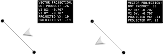
Figure 2.27. A positive dot product means the ship is on the left side of the vector. A negative dot product means its on the right.
You now have a foolproof way of knowing on which side of the line the ship is. v2 has become a clear environmental boundary.
This bit of information has amazing potential:
You can use it find out whether an object has crossed a boundary, no matter what the angle of the vector is.
You can trigger a collision.
Don't worry about completely understanding exactly how this works just yet. We'll take a detailed look at the math behind it and why it's useful in the section on collision a little further ahead.
Crossing the boundary, however, is only the first part of the problem. You also need to know the exact point where the intersection happens. Let's figure that out next.
Now that we have a way to figure out if the spaceship has collided with the vector, we need to find out exactly where the collision happened. But let's first consider when it won't happen.
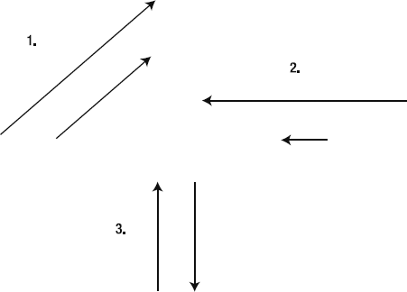
When two vectors are parallel, they'll never intersect. And that means that a collision between them will never happen. What do I mean by "parallel vectors"? Those are vectors that are pointing in exactly the same direction or exactly opposite directions. Figure 2-28 shows three examples of parallel vectors. They run alongside each other like the two rails of a train track. You can always tell when two vectors are parallel because their dx and dy values will be exactly the same.
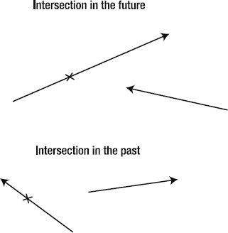
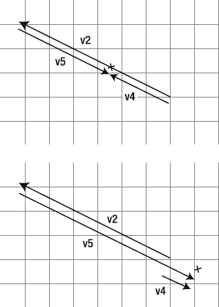
Most vectors aren't parallel and will intersect at some point or another. Sometimes the intersection will happen in the future; other times the intersection has already happened in the past. Figure 2-29 illustrates two pairs or intersecting vectors.
Finding the intersection point is not hard. A little bit of math comes to our rescue again. Figure 2-30 illustrates the general idea behind finding the intersection point. The key is that you need to extend a third vector between v1 and v2. The third vector helps us calculate the coordinates of the intersection point. v3 is like a ghost vector that quietly and invisibly contributes a bit of extra data that your calculations need to find the intersection point.
The math involves a value called a perpendicular dot product. It's nothing to be afraid of! In fact, it's exactly the same as finding an ordinary dot product, except that instead of using v1 in the equation, you use v1's normal: the perpendicular vector. The perpendicular dot product is sometimes called the perp product or perp-dot product. In the example code, it's represented by a variable named perpProduct.
perpProduct = v1.ln.vx * v2.dx + v1.ln.vy * v2.dy;
No big deal, right? We've used this sort of calculation before. You can use either the right or left normal, and the result will be the same.
Here's how to use a perp-dot product to find the intersection point of v1 on v2:
Find the perp-dot product of
v3andv2.perpProduct1 = v3.ln.vx * v2.dx + v3.ln.vy * v2.dy
Find the perp-dot product of
v1andv2.perpProduct2 = v1.ln.vx * v2.dx + v1.ln.vy * v2.dy
Find the ratio between
perpProduct1andperpProduct2. This is just a matter of dividing the two values together. (tis for tangent, the point of intersection, and is a common convention for representing this value.)t = perpProduct1 / perpProduct2
With the value of
tin our pocket, we now have enough information to pinpoint the precise intersection point with real x and y coordinates. We can find this by addingv1's start point to its velocity and multiplying it byt.intersectionX = v1.a.x + v1.vx * t intersectionY = v1.a.y + v1.vy * t
And there we have the coordinates for the intersection point.
I can just imagine the giddy delight on the faces of the first mathematicians who first figured this out. Mathematicians: 1; Mysteries of the Universe: 0.
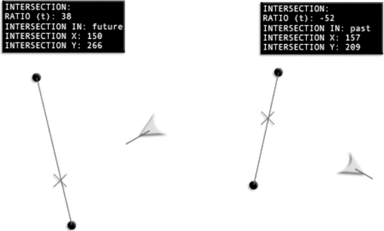
Now let's see how this works in a live example. In the chapter's source files, you'll find a folder called Intersection. Run the SWF, and you'll see something that looks like Figure 2-31. The ship's intersection point with the line is marked by a small crosshair. (The ship's motion vector has been scaled by 10 so that you can see it clearly.) You can move the drag handles to change the line's inclination, and the intersection mark will have no problem keeping up. The status box also displays whether the intersection happens in the future or might have happened in the past.
Because the intersection is found using the ship's velocity, not the direction its pointing in, the ship often looks like it's going to miss the intersection. But the intersection point is always predicted with spooky, pinpoint accuracy.
Again, most of the code in the source files is routine. Here, we'll look at the important sections that create the intersection. The names of the vectors are the same as in Figure 2-30.
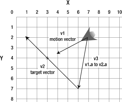
First, we need three vectors: v1 is the ship's motion vector, v2 is the target vector on which we want to find the intersection, and v3 is the helper vector between v1 and v2 that helps to calculate the correct point.
//v1: the ship's motion vector_v1.update ( _shipModel.xPos, _shipModel.yPos, (_shipModel.xPos + _shipModel.vx), (_shipModel.yPos + _shipModel.vy) );//v2: the vector between the drag handles_v2.update(_handle1.x, _handle1.y, _handle2.x, _handle2.y);//v3: the vector between v1 and v2_v3.update(_shipModel.xPos, _shipModel.yPos, _handle1.x, _handle1.y);
Next, we calculate the ratio of the perp-dot product of v3 and v2, and of v1 and v2.
var t:Number
  = VectorMath.perpProduct(_v3, _v2)
  / VectorMath.perpProduct(_v1, _v2);
The VectorMath class has a perpProduct method that does this calculation for us.
static public function perpProduct(v1:VectorModel, v2:VectorModel):Number
{
  var perpProduct:Number = v1.ln.vx *  v2.dx + v1.ln.vy * v2.dy;
  return perpProduct;
}
Next, we combine v1's position and velocity, and multiply it by the ratio (t) to find the intersection point.
var intersection_X:Number = _v1.a.x + _v1.vx * t;
var intersection_Y:Number = _v1.a.y + _v1.vy * t;
Finally, we position the intersection mark.
_mark.x = intersection_X;
_mark.y = intersection_Y;
(The visible X that you see on the stage is created from the IntersectionMark class in the vectors package. It draws a simple crosshair.)
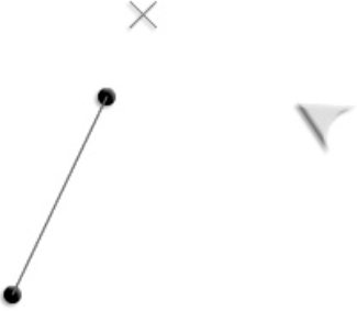
There's one small problem with this example that I'm sure you've noticed. The intersection mark doesn't know that it should be limited to the magnitude of v2. It thinks that v2 goes on forever. As a result, it finds intersections beyond the limits of v2, as you can see in Figure 2-32. This isn't actually incorrect as it has been coded, but we would have a much more usable system if intersections were found only within the vector's point A and B.
We need to conjure up a little more vector magic to help us solve this problem.
In the chapter's source files, you'll find a folder called LimitingIntersection. Run the SWF, and you'll notice that the intersection point is now mapped only on the length of the vector, and not beyond it. This is very easy to implement. The source code is exactly the same as the previous example, except for these additions:
Extend a vector from
v2's start point to the intersection point.var v4:VectorModel = new VectorModel (_v2.a.x, _v2.a.y, intersection_X, intersection_Y);
Extend another vector running in the opposite direction from
v2's end point to the intersection point.var v5:VectorModel = new VectorModel (_v2.b.x, _v2.b.y, intersection_X, intersection_Y);
If the magnitude of either of these vectors is larger than
v2's magnitude, then you know that the intersection point falls beyondv2's bounds.if(v4.m > _v2.m || v5.m > _v2.m) {//The intersection point is outside the magnitude of v2intersection_X = 0; intersection_Y = 0; }
You can decide what actions to take on this. In this simple example, the intersection point is moved to position 0,0, which keeps it out of trouble. In a more complex game environment, you'll probably have many more variables to consider.
Figure 2-33 illustrates how this works. It's a very simple concept, and once you become more comfortable using vectors, it's the kind of thing you'll easily be able to figure out for yourself.
You can relax now! We've covered almost everything you need to know about vectors for 2D game design. The theory class is over, and we can now put some of this new information to practical use.
Now we're going to solve the classic problem of line-versus-point collision. This is collision between a two-dimensional line segment and a one-dimensional point. Points are objects with no height or width, just a position. They're often called particles, so that's how I'll be referring to them from now on. Collisions between lines and particles are the most basic form of collision detection that you can do. Once you understand these fundamentals, you'll find shape-versus-shape collision, which we'll look at in the next chapters, much easier to comprehend.
As you know by now, vectors have two sides: a left side and a right side. A particle can collide with either side. But how does the particle know which side of the vector it's on? And how does it know which is the right side or the wrong side for it to be on? This is important information for line-versus-particle collision. These aren't trivial problems to solve, but we can use some nifty vector tricks to help us.
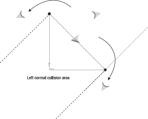
First, let's looks at collision from one side of the line. Run the Collision.swf file in the chapter's source file (You'll find it in the Collision subfolder.) You can fly the ship anywhere around the stage, but it's not able to cross the vector from the right side into the left side. The ship's center point is blocked by the line. (In this example, the ship's center point is our one-dimensional particle.) And although you can fly around the line, you can't cross into the space defined by the vector's left normal. If you do, the ship will be placed at its intersection point with the line. This looks like a bug, but it's actually just the expected behavior of this system. We'll be improving this to handle double-sided collision later in the chapter.
You can use the drag handle to change the magnitude or angle of the vector however you like, and you'll see that the effect remains the same no matter what its orientation is. You can fly into the line at any speed, and the ship won't be able cross it. It looks and feels like a solid boundary, but it's really just math! Figure 2-34 illustrates what you'll see when you run the SWF.
There are two important things going on in this example:
The collision-detection system "knows" the magnitude and orientation of the line to create the collision space. This allows the ship to fly around the line's edges.
The left side of the line has been created as the collision boundary. The ship is stopped dead in its tracks on the vector if it tries to cross from the right side to the left.
We'll look at these features one at a time. Here's most of the example's enterFrameHandler, so you can see the context of the code we'll be examining:
private function enterFrameHandler(event:Event):void
{
//Update the ship model
_shipModel.update();
StageBoundaries.wrap(_shipModel, stage);
//v1: the ship's movement vector
_v1.update
(
_shipModel.xPos, _shipModel.yPos,
(_shipModel.xPos + _shipModel.vx),
(_shipModel.yPos + _shipModel.vy)
);
//v2: the drag handle vector
_v2.update(_handle1.x, _handle1.y, _handle2.x, _handle2.y);
//v3: the vector between v1 and v2
_v3.update
(_shipModel.xPos, _shipModel.yPos, _handle1.x, _handle1.y);
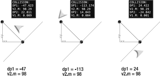
//Dot products
var dp1:Number = VectorMath.dotProduct(_v3, _v2);
var dp2:Number = VectorMath.dotProduct(_v3, _v2.ln);
//Check if ship is within the vector's scope
if(dp1 > -_v2.m && dp1 < 0)
{
//Check if ship's motion vector has crossed the vector from right to left
if(dp2 <= 0)
{
//Find the collision vector
var collisionForce_Vx:Number = _v1.dx * Math.abs(dp2);
var collisionForce_Vy:Number = _v1.dy * Math.abs(dp2);//Move ship out of the collision_shipModel.setX = _shipModel.xPos - collisionForce_Vx; _shipModel.setY = _shipModel.yPos - collisionForce_Vy;//Set the velocity to zero_shipModel.vx = 0; _shipModel.vy = 0; } }//Display the result in a status box//... }
Note
Important! For this system to work accurately, you need to make sure that changing the ship model's setX and setY properties leads to a CHANGE event being dispatched. If it doesn't, the ship's view won't update immediately, and the collision will appear to be off by one frame. In the ShipModel class, setX and setY modify the public xPos and yPos properties, and those in turn dispatch a CHANGE event that updates the ship's view on the stage.
The vector creates a collision boundary for the ship. To create that boundary, we need to know the vector's magnitude and orientation. Where is it and how long is it? The ship needs to know where the line starts and ends so that it can fly around it.
v2 is the vector that you can see on the stage. An invisible vector called v3 runs between the ship and v2's start point. The dot product of these vectors can tell us whether the ship is within the line's scope.
If the dot product is greater than zero, the spaceship will be beyond
v2'sscope, at the bottom.If the dot product is less than the negative of
v2's magnitude, then the ship is beyondv2's scope at the top.
If this sounds confusing, a picture will help. Take a look at Figure 2-35 and compare the value of dp1 with v2.m (the magnitude of the line). If dp1 is greater than −98 or less than 0, the ship is in a position to possibly collide with the line.
Here's the code that figures this out and checks whether a collision might be possible:
var dp1:Number = VectorMath.dotProduct(_v3, _v2);

if(dp1 > -_v2.m && dp1 < 0)
{... a collision might be possible...
If this is false, the ship is free to fly around the top or bottom of the line. This relationship remains the same, even if v2 changes its magnitude or orientation, so it's an extremely useful bit of information.
dp2 is the dot product of v3 (the vector between the ship and the start point of v2) and v2's normal. Earlier in the chapter, we looked at how we can use this dot product to find out on which side of the line the ship is. Let's review that again here, as it's crucial to understanding how vector-based collision works.
Take a look at Figure 2-36. The spaceship is flying straight toward the line. It's probably going to hit it, so it will be useful to know when it hits and with how much force. In these examples, the collision plane is represented by a vector called v2.
To get the information we need, we extend a vector from the spaceship to the collision plane's start point. In these examples, this new vector is called v3, and you can see it illustrated in Figure 2-37. This new vector will help us get a bit more extra information about the collision.
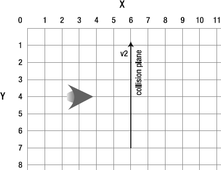
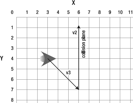
There is a magic number that will help us easily solve the collision problem. That number is the dot product between the new vector, v3, and v2's normal. (You can use either the left or right normal, the result will be the same.) Figure 2-38 shows how this dot product is found. In these examples, this dot product is called dp2.
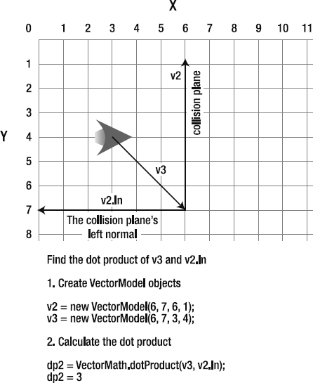
The dot product in this example has a value of 3. Does that value seem significant in some way? It is. Look carefully, and you'll see that that the spaceship is three cells away from the collision plane. As illustrated in Figure 2-39, the dot product can tell you exactly how far away the ship is from the line.
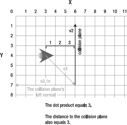
This remarkable coincidence is like a buried treasure hidden deep within the math. It holds true no matter what the angle of the collision plane is.
Because you can use this information to tell how far the ship is away from the line, you can also use it to figure out if there has been a collision. Not only that, but it can tell you with how much force the ship has collided.
Take a look at Figure 2-40, and you'll see what I mean. When the ship is exactly on the line, the dot product is zero. When it has crossed the line by three cells, the dot product is −3.
This means that you know the ship is colliding with the line if the dot product is less than zero. That's the flag that triggers a collision. In the Collision example code, it's represented like this:
if(dp2 <= 0)
{
  //...We have a collision!
Now we have a way to detect a collision. Next, we need to find a way to resolve the collision.
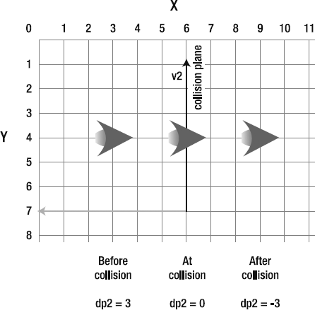
In Figures 2-35 through 2-39, the spaceship and the collision plane are aligned to the x and y axes. This makes the math really easy to understand and visualize. But in a real-world collision, it's likely that the ship and line will be colliding at weird angles. Fortunately, the math holds up no matter at what angle the collision happens.
When the ship collides with the line, we need to know by how much it has crossed the line. This is important so we can move the ship out of the collision. We need to move it back to the exact point of collision with the line (the point where the dot product is zero). In Figure 2-39, it's easy to see that the ship has overshot the line by three cells. If we move the ship back by 3, it will be positioned exactly at the point of collision.
We can say that −3 is the ship's collision vector. The collision vector has a magnitude of 3. If we know the direction of the collision and we know the magnitude, we can resolve the collision.
As you've seen, the dot product will always tell you the magnitude of the collision vector. We have that number in the bag. However, we don't always know the direction of the collision. Take a look at Figure 2-41 for an example. It shows how both the ship and the line are colliding at strange angles. We know that the dot product is 4 (rounded). That's the collision vector's magnitude. But we can't create a collision vector until we also know the direction of the collision.
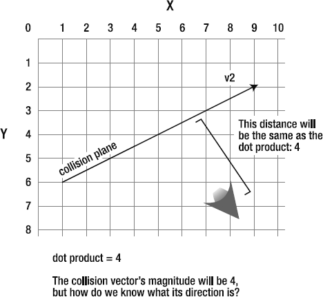
Figure 2.41. The ship has collided with the line. The magnitude of the collision will be the same as the value of the dot product. But what's the direction?
How can we figure out from which direction the ship is colliding with the line? Surprise—we already know it! It's the ship's motion vector, v1.
Figure 2-42 shows the spaceship's motion vector, v1. It's definitely pointing in the right direction. The only problem is that it's too long. Its magnitude is 7 (rounded). What would Goldilocks do?
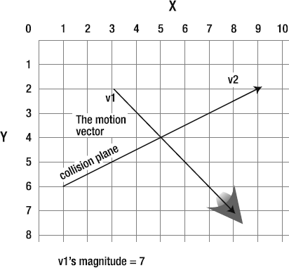
Figure 2.42. The ship's motion vector is pointing in the right direction, but its magnitude is too long.
We need a vector that's pointing in the same direction as v1 but has the same magnitude as the dot product. Aha! That should ring a bell.
We can use a unit vector to help solve this problem. Remember that normalized unit vectors are the smallest size a vector can be. They have the magical property of pointing in a specific direction, but can be scaled to any size. Unit vectors are the "Drink Me!" of Vectorland.
How can we use a unit vector in this case?
Normalize the ship's motion vector,
v1. That will allow us to keep its direction but scale it to any other size.Multiply
v1's unit vector by the value of the dot product, 4. The resulting vector is the new collision vector.
Figure 2-43 shows how v1's unit vector is scaled by the dot product to create the collision vector. Here's the code in the Collision example file that does this work.
var collisionForce_Vx:Number = _v1.dx * Math.abs(dp2);
var collisionForce_Vy:Number = _v1.dy * Math.abs(dp2);
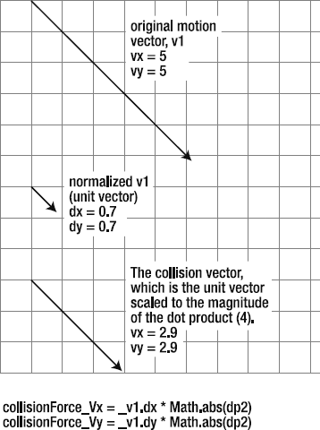
The new collision vector precisely describes the force of the collision. You can see in Figure 2-44 that it fits exactly in the space between the line and ship. (It's been rounded up to 3 because we're working with whole pixel values.) It tells us how far the ship has intersected the line.
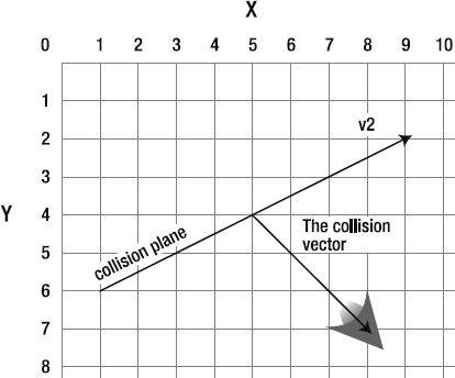
Next, we need to use this information to move the ship back to the collision point. Why? Because the collision plane is supposed to be a solid surface. The spaceship should never seem to cross the line. It should stop right on the collision plane.
All we need to do is take the ship's position and subtract the collision vector. That gives us the collision vector's start point. That point happens to be the exact point of collision between the ship and the line. If we move the ship to that point, we've resolved the collision. Figure 2-45 illustrates how this works.
The code in the Collision example file that does the work looks like this:
_shipModel.setX = _shipModel.xPos - collisionForce_Vx;
_shipModel.setY = _shipModel.yPos - collisionForce_Vy;
It also sets the ship's velocity to 0, which puts on the brakes.
_shipModel.vx = 0;
_shipModel.vy = 0;
With the help of normals, normalized unit vectors, and the dot product, we have a simple solution to a complex problem.
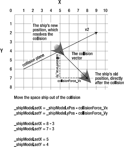
Figure 2.45. Subtract the collision vector from the spaceship's position to find the exact point of collision with the line.
Note
Collision detection in video games tends to fall into two main categories:
Posteriori: Checking for a collision after the collision has already happened.
Priori: Checking for a collision before it happens
This book uses posteriori collision detection. Because all the collision objects are using the MVC system, the code can model the collision and resolve it before the result is displayed on the stage. This allows us to implement stable and accurate collision detection that doesn't suffer from off-by-one-frame errors.
When an object hits an angled line, it needs to ricochet at the correct angle. Here's where the technique of projection saves the day. Let's take a look at the general procedure for making an object bounce.
First, we need to combine the motion vector with the angle of the line with which it's colliding. The first step is to project v1 onto v2 and v2's normal. Figure 2-46 illustrates this. (The projected vectors are called p1 and p2 in this example.)
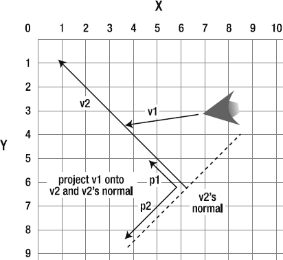
The next thing to do is reverse the p2 vector. We want our collision object to bounce, so reversing this projection will create a force directly opposite to the collision force. To reverse a vector, simply multiply its vx and vy values by −1. Next, add the vx and vy values of both projected vectors together. This gives you a new bounce vector. Figure 2-47 illustrates this.
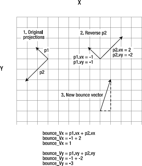
The last step is to apply this new bounce vector to the collision object's velocity (v1). The object will bounce away at exactly the right angle, no matter what the angle of the line is. Compare the bounce vector in Figure 2-47 with the way that it has been applied in Figure 2-48, and you'll see that it's exactly the same vector.
Let's see how to translate these concepts into AS3.0 code. In the chapter's source files, you'll find a folder called Bounce. Run the SWF and you find a working example, as shown in Figure 2-49.
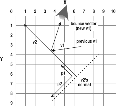
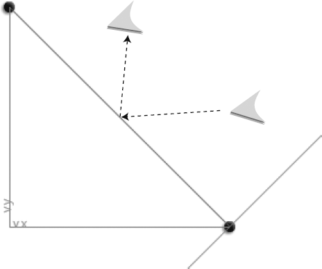
The code is almost identical to the Collision example. Let's look at how the new code that makes the spaceship bounce.
Project the ship's motion vector (v1) onto v2 and v2's normal. This creates two new projected vectors. (Again, creating VectorModel objects for them isn't necessary because we need only their vx and vy values.)
//Find the dot product between v1 and v2var dp3:Number = VectorMath.dotProduct(_v1, _v2);//Find the projection of v1 onto v2var p1_Vx:Number = dp3 * _v2.dx; var p1_Vy:Number = dp3 * _v2.dy;//Find the dot product of v1 and v2's normal (v2.ln)var dp4:Number = VectorMath.dotProduct(_v1, _v2.ln);//Find the projection of v1 onto v2's normal (v2.ln)var p2_Vx:Number = dp4 * _v2.ln.dx; var p2_Vy:Number = dp4 * _v2.ln.dy;
Next, reverse the projection on v2's normal by multiplying it by −1. This will create the bounce effect.
p2_Vx *= −1;
p2_Vy *= −1;
Then add up the projected vectors' vx and vy values to create a new bounce vector.
var bounce_Vx:Number = p1_Vx + p2_Vx;
var bounce_Vy:Number = p1_Vy + p2_Vy;
Finally, assign the bounce vector to the spaceship's velocity. Optionally, multiply it by another number to exaggerate or dampen the bounce effect. Multiplying it by 0.8 reduces the bounce force by 20%, which simulates loss of energy when the ship hits the line. Multiplying it by a number greater than 1 will make the bounce force more powerful than the original collision force, which creates a trampoline effect. Multiplying by 0 means that there's no bounce at all.
_shipModel.vx = bounceVx * 0.8;
_shipModel.vy = bounceVy * 0.8;
Bounce solved!
In this book, I've chosen to collide and bounce objects using these steps:
When the objects collide, move the objects to the exact point of the collision.
Bounce them apart from that collision point.
There is a problem with this: it's not entirely accurate. By repositioning the object at the point of collision, its motion vector can become truncated. Part of its movement from the previous frame might be lost.
Imagine that you're driving along the street and absently run through a red light. You slam on the brakes and skid halfway through the intersection, leaving a long black trail of molten rubber tracing you path. You sheepishly back up, and wait for the light to change.
This is how this the collision code is working. It stops the car exactly at the red light, whether or not the car still has any momentum left. That momentum—the skid marks—is lost. It's not added to the car's new position when the lights change.
I've chosen this style of collision because, for games, it can actually appear more accurate. By positioning colliding objects exactly at the point of collision, it allows the eye to see the point of contact between objects. This is a psychological cue that makes the brain think, "They collided!"
Without this visual cue, the collision can appear less precise or fuzzy, because we never see the objects actually touch each other. Instead, we see them a few pixels apart before they collide, and then a few pixels apart in the next frame when they bounce apart. Even though this might be more accurate, we never see them touch.
This is purely a stylistic decision, so you'll need to decide whether it's appropriate for your games. If you prefer greater accuracy, don't position the colliding object at the collision point. Instead, subtract the collision vector from p2 and reverse it. You can call the new vector that results the "momentum vector." The distance from the collision point to the momentum vector's point B is the new position you should give your object in the next frame. This way, none of the object's original momentum is lost.
To keep the examples so far as clear as possible, they've involved only one line. But you can add as many lines as you like, and join them together to form solid shapes. Just push all the lines into an array and loop through the array each frame to check for collisions.
The one thing you need to remember is that only one side of the line should face the collision object (the spaceship in our example) at all times. In the last few examples, the ship could fly to the right of the line, but not directly behind it on its left side. There shouldn't be any chance that the object enters the dreaded "left normal collision area" illustrated earlier in Figure 2-34.
With that in mind, you could easily create an irregular terrain for a planet surface or perhaps the interior of a lunar cave, as shown in Figure 2-50. The right side of the lines represents negative space, and the left side represents positive space.
You can also use these techniques to create polygons of any shape. But there's a problem that you need to take into account. Take a look Figure 2-51. Even if your collision object is facing the right side of a line, it will still fall into the collision area from a line on the opposite side of the polygon.
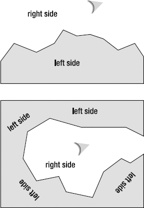
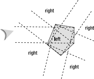
Figure 2.51. The ship may be to the right of the closest line, but it's falling within the left normal collision area from a line on the opposite side of the polygon.
There is a simple solution to this: check only for collisions with lines that intersect with the ship's motion vector. If there's an intersection with more than one line, just check for a collision with the closest intersecting line. Figure 2-52 shows an example.
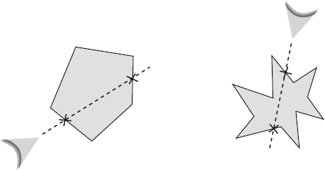
Try it! If you're a little uncertain about checking collisions on multiple objects, you'll find more details in Chapter 3.
Note
If you're using Verlet integration, you can use vectors to create Verlet sticks and Verlet structures. These are shapes created by drawing vectors between particles and constraining them to a fixed distance so that they become "solid" and react like solid objects when they collide. They can be used as the basis for building very reliable physics engines. Keith Peters has an excellent introduction to this subject in AdvancED ActionScript 3.0 Animation (friends of ED, 2008), which is a perfect complement to this chapter.
We're now going to use our newfound vector voodoo to create a collision system that works on both sides of the line. To see what it can do, run the doubleSidedCollision SWF in the chapter's source files. Fly the ship around both sides of the line, and bounce against it a few times. Figure 2-53 shows what you'll see.
Just what we need! There are actually quite a few different approaches you can take to doing this, but I'm going to show you a method that's both bulletproof and versatile. To make it work, we need to use all of our now formidable number of vector tricks. There's a lot going on in this code, so now might be a good time to review any concepts you're a little fuzzy on.
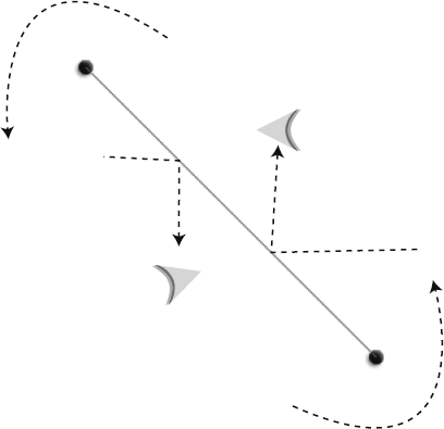
Take a look at the DoubleSidedCollision.as file, and I'm sure you'll notice a lot of code you recognize. Here's how it works in general terms:
We need to know which side of the line the spaceship is on. Is it on the right or left side? A new variable called
_lineSidetracks this.The code uses a dot product to find out on which side of the line the ship is. The code uses the dot product to set the
_lineSidevariable to"left"or"right".The collision boundary is based on the value of the
_lineSidevariable. It's exactly the same technique we used in the previous two examples, but modified to work for collision on both the right and left.The
_lineSidevariable is reset when the ship moves around the edges of a line using the same technique used in the previous two examples. The_lineSidevariable is also reset when the ship wraps around the edges of the stage.
Here's the important code from the enterFrameHandler that does all this work. You'll notice that the code for creating the bounce vector has been offloaded to the VectorMath class. Take a look at the VectorMath.bounce method. It's almost identical to the code in the previous example, except that it returns VectorModel objects to the main program.
//The dot product that tells you whether the ship is within//the scope of the line's magnitudevar dp1:Number = VectorMath.dotProduct(_v3, _v2);//The dot product that tells you which side of the line//the ship is onvar dp2:Number = VectorMath.dotProduct(_v3, _v2.ln);//If the ship is within the scope of the line's magnitude//then set its line side to left or rightif(dp1 > -_v2.m && dp1 < 0 ) { if(_lineSide == "") { if(dp2 < 0 ) { _lineSide = "left"; } else { _lineSide = "right"; } } } else {//If the ship is not within the line's scope (such as rounding//a corner) clear the _lineSide variable._lineSide = ""; }//Reset the _lineSide variable if the ship has wrapped//around the edges of the stageif(_shipModel.yPos > stage.stageHeight || _shipModel.yPos < 0 || _shipModel.xPos < 0 || _shipModel.xPos > stage.stageWidth) { _lineSide = ""; }
//Create an environmental boundary based on whether//the ship has collided from the right or leftif(dp2 > 0 && _lineSide == "left" || dp2 < 0 && _lineSide == "right") {//Create the collision vectorvar collisionForce_Vx:Number = _v1.dx * Math.abs(dp2); var collisionForce_Vy:Number = _v1.dy * Math.abs(dp2);//Move ship out of the collision_shipModel.setX = _shipModel.xPos - collisionForce_Vx; _shipModel.setY = _shipModel.yPos - collisionForce_Vy;//Create a bounce vectorvar bounce:VectorModel = VectorMath.bounce(_v1, _v2);//Bounce the ship_shipModel.vx = bounce.vx * 0.8; _shipModel.vy = bounce.vy * 0.8; }
There are no new techniques here. It just includes some extra logic to figure out on which side of the line the ship is. Let's untangle it and figure out what's happening.
First, we need our usual pair of loyal dot products to help us make sense of our space. They'll be playing the same role as in the previous examples.
var dp1:Number = VectorMath.dotProduct(_v3, _v2);
var dp2:Number = VectorMath.dotProduct(_v3, _v2.ln);
What side of the line is the spaceship on? We only care if the ship is within the scope of the line's magnitude, because that's when a collision may be likely. If it's not—if the ship is beyond the top or bottom edge of the line—then the _lineSide variable should be cleared so that it can be set to something else later. If it is within the line's scope, then use dp2 to find out whether it's on the left or right side of the line, and set _lineSide to that value.
//Is the ship within the scope of v2's magnitude?if(dp1 > -_v2.m && dp1 < 0 ) {//If the answer is yes, set _lineSide to the correct valueif(_lineSide == "") { if(dp2 < 0 ) { _lineSide = "left"; }
else
    {
      _lineSide = "right";
    }
  }
}
else
{
  //If the ship is not within the line's scope (such as rounding
  //a corner) clear the _lineSide variable.
  _lineSide = "";
}
We need to clear the _lineSide variable if the ship wraps around the edges of the stage. If we don't do this, the code might think that the ship is on the wrong side of the line when it reemerges from the opposite side of the stage.
if(_shipModel.yPos > stage.stageHeight
|| _shipModel.yPos < 0
|| _shipModel.xPos < 0
|| _shipModel.xPos > stage.stageWidth)
{
   _lineSide = "";
}
Now that we know which side of the line the ship is on, we need to check if it crosses the line. For example, if we know that the ship is on the right, and dp2 suddenly becomes less than zero, we know that the ship has just intersected. We have a collision!
if(dp2 > 0 && _lineSide == "left"
|| dp2 < 0 && _lineSide == "right")
{...
The logic behind the collision code is identical to the previous examples. The only difference is that it has been made more compact by delegating the work of creating the bounce vector to the VectorMath class.
//Create the collision vectorvar collisionForce_Vx:Number = _v1.dx * Math.abs(dp2); var collisionForce_Vy:Number = _v1.dy * Math.abs(dp2);//Move the ship out of the collision_shipModel.setX = _shipModel.xPos - collisionForce_Vx; _shipModel.setY = _shipModel.yPos - collisionForce_Vy;//Create a bounce vectorvar bounce:VectorModel = VectorMath.bounce(_v1, _v2);
//Bounce the ship
_shipModel.vx = bounce.vx * 0.8;
_shipModel.vy = bounce.vy * 0.8;
As you can see, it's nothing new—just a bit of simple logic. You can use this technique to create solid objects and complex environments, like a maze, just as you could with the previous examples. Push all the lines into an array and loop through them to check for collisions. However, because this technique depends on a variable to track the side of the line the ship is on, you'll also need a lineSide variable for each line. You can store and track these lineSide variables in another array.
For the grand finale, let's round up all the star and bit players of this chapter, and get them to help us solve one of the classic problems of game design: a falling particle hitting, bouncing, and sliding off a line. There are many ways you could do this. I'll show you the way I've done it and explain all the principles involved. My hope is that you'll take this information and run with it to build system that's customized for a game of your own.
You'll find the sample file in the BouncingParticle folder. Run the SWF file, and you'll see something that looks like Figure 2-54. A particle falls, hits a line, and bounces. If it gradually comes to a rest on the line, it will slide off. You can move the drag handles to change the orientation of the line.
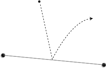
Note
This example is not coded to handle collision with a moving line. You'll see some weird things happen to the particle if you move the line upwards while the particle is resting on it. The line's drag handles are implemented with startDrag and stopDrag. When you move objects with the mouse using startDrag and stopDrag, Flash updates the position of those objects on the stage at a different rate than the movie's frame rate. That means that their change in position won't be synchronized with the code in your enterFrameHandler. For a reliable collision system with a moving line, you'll first need to implement a drag-and-drop system that runs within the same enterFrameHandler as the rest of the collision code. (Chapter 10 of my book Foundation Game Design with Flash describes such a system in detail.)
Also, if you move the line while the particle hits it or is resting on it, you may want to transfer some of that force to the particle. To do that, you'll need to work out the force and the direction of that force, and add that to the particle's velocity. Does that sound strangely familiar? It should, because it just means you need to figure out the drag handle's motion vector when it moves. I'll let you work out the details, but everything you need to know to do this is in this chapter.
You might not find it surprising that all we're doing in this example is mixing together our ingredients in a slightly different combination. Here's the basic recipe:
Add the force of gravity to the particle's velocity.
When the particle crosses the line, figure out by how much it has overshot. That becomes your collision force. Add the current gravity to the collision force. Use these values to move the particle out of the collision
Calculate bounce as in the previous examples.
If you want the particle to slide off an inclined line, you need to calculate friction. This is very easy to do: add the projection of
v1ontov2to the particle's velocity.
Now, let's see how I've cooked this recipe for the BouncingParticle example.
First, I created a particleModel object. It has a model and view.
private var _particleModel:ParticleModel = new ParticleModel();
private var _particleView:ParticleView = new ParticleView(_particleModel);
The ParticleModel class extends the AVerletModel class. All the important code is actually in the AVerletModel class. It's essentially the same as the ShipModel class we've been using in the previous examples, but simpler and with an added provision for adding gravity to the object's velocity. In Chapter 3, I'll explain exactly how AVerletModel works and how to extend it to create new classes. For now, all you need to know is that the code that makes the particleModel object move is in the AVerletModel class. Its most important part is its update method.
public function update():void
{
  temporaryX = xPos;
  temporaryY = yPos;

  vx += acceleration_X;
  vy += acceleration_Y;

  vx *= friction;
  vy *= friction;

  xPos += vx + friction_Vx + gravity_Vx;
  yPos += vy + friction_Vy + gravity_Vy;

  previousX = temporaryX;
  previousY = temporaryY;

  //This "update" event is not used in this example,
  //so you can ignore it for now:
  dispatchEvent(new Event("update"));
}
Notice that gravity is now a force that can potentially act on the particle's position.
xPos += vx + friction_Vx +gravity_Vx; yPos += vy + friction_Vy +gravity_Vy;
It can be applied on both the x and y axes. In this example, it's going to be applied only on the y axis. (The particle's friction property is set to 1 by the application, so its own internal friction is not a factor in this example.)
In the BouncingParticle application class, the _particleModel's gravity is set to 0.1 when its view is added to the stage.
addChild(_particleView);
_particleModel.setX = 150;
_particleModel.setY = 150;
_particleModel.friction = 1;
_particleModel.gravity_Vy = 0.1;
The only difference in the BouncingParticle code from the previous example is in the if statement block that checks for a collision. Here's that entire section:
if(dp2 > 0 && _lineSide == "left"
|| dp2 < 0 && _lineSide == "right")
{
   //Create the collision vector
   var collisionForce_Vx:Number = _v1.dx * Math.abs(dp2);
   var collisionForce_Vy:Number = _v1.dy * Math.abs(dp2);
//Move the particle out of the collision_particleModel.setX = _particleModel.xPos - collisionForce_Vx; _particleModel.setY = _particleModel.yPos - collisionForce_Vy - _particleModel.gravity_Vy;//Find the projection vectorsvar p1:VectorModel = VectorMath.project(_v1, _v2); var p2:VectorModel = VectorMath.project(_v1, _v2.ln);//Calculate the bounce vectorvar bounce_Vx:Number = p2.vx * −1; var bounce_Vy:Number = p2.vy * −1;//Calculate the friction vectorvar friction_Vx:Number = p1.vx; var friction_Vy:Number = p1.vy;//Apply bounce and friction to the particle's velocity_particleModel.vx = (bounce_Vx * 0.6) + (friction_Vx * 0.98); _particleModel.vy = (bounce_Vy * 0.6) + (friction_Vy * 0.98); }
Let's look at how it works.
When a collision is detected, the particle is moved out of the collision by subtracting the force of impact from its velocity. Gravity is an additional force, so we need to subtract that as well.
_particleModel.setX
   = _particleModel.xPos
   - collisionForce_Vx;

_particleModel.setY
   = _particleModel.yPos
   - collisionForce_Vy
   - _particleModel.gravity_Vy;
Gravity is acting only on the y axis. It's adding to the particle's vy to pull it down. By subtracting it from the collision vector, gravity is neutralized. It means that when the particle is resting on the line, it's being pushed down and pushed up by exactly equal forces. This allows the friction effect to work without being crushed by the force of gravity.
Next, we need to find the projection vectors. The VectorMath.project method does this work for us, and returns the projection vectors as VectorModel objects.
var p1:VectorModel = VectorMath.project(_v1, _v2);
var p2:VectorModel = VectorMath.project(_v1, _v2.ln);
Here's where it gets interesting. Let's do a quick review and introduce some new terms.
We have two projection vectors, and each projection represents a component of the particle's velocity. The motion vector is split down the middle into two separate parts:
p1is the projection ofv1ontov2. This represents the particle'svxprojected onto the line. It's known as the parallel component. The parallel component handles the friction on the surface of the line. This makes sense if you think of it as the "across" axis of the vector's plane.p2is the projection ofv1ontov2's normal. This represents the particle'svyprojected onto the line. It's known as the perpendicular component. The perpendicular component handles bounce. This makes sense because it's the "up and down" axis of the vector's plane.
Figure 2-55 illustrates these components.
The short story is that p2 handles bounce, and p1 handles surface friction. And if you understand that, the rest is almost laughably easy. No, really, it is! You'll see that it's true in the next calculations.
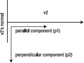
We calculate bounce by reversing p2 and adding it to the particle's velocity.
var bounce_Vx:Number = p2.vx * −1; var bounce_Vy:Number = p2.vy * −1; _particleModel.vx =(bounce_Vx * 0.6)+ (friction_Vx * 0.98); _particleModel.vy =(bounce_Vy * 0.6)+ (friction_Vy * 0.98);
This is exactly the same as the way we calculated bounce in the previous example; the context is just slightly different.
Friction is p1. It doesn't need to be reversed or have any calculations done to it. However, if you want the particle to gradually slow down, multiplying it by a number less than 1 (such as 0.98) will do the trick.
var friction_Vx:Number = p1.vx;
   var friction_Vy:Number = p1.vy;

   _particleModel.vx = (bounce_Vx * 0.6) + (friction_Vx * 0.98);
   _particleModel.vy = (bounce_Vy * 0.6) + (friction_Vy * 0.98);
Experiment with different bounce and friction multipliers until you find a combination you like.
Line-versus-particle collision solved!
Before you can use assets like images, fonts, and sounds in your game, you need to embed them. If you're using the Flash Professional IDE, you can embed them directly into your SWF using the IDE. Check Flash's documentation on how to do this if you don't already know how. Here, I'm going to show you how to embed assets using pure AS3.0 code, which is often more convenient and possibly easier to manage, especially if you're writing a lot of code.
Use the Embed metatag to embed the font and assign it to a class. This must be done in the class definition, where you declare all your instance variables. Here's the basic format:
public class AnyClass extends Sprite
{

[Embed(systemFont="Andale Mono", fontName="embeddedFont",
fontWeight="normal",
advancedAntiAliasing="true", mimeType="application/x-font")]

  //... declare class instance variables
This embeds the Andale Mono font, which is a font installed on my system. You can use the name of any font that you have installed.
Its fontName parameter is "embeddedFont". If I want to use this font anywhere else in the class, I need to refer to it by this name. The other parameters should be self-evident.
You'll notice that there's a Class variable just below the Embed tag called EmbeddedFontClass.
private var EmbeddedFontClass:Class;
The font is actually stored in this class. Yes, I know what you're thinking: There's no assignment operator to show this, and it doesn't look like it could possibly be standard AS3.0 syntax. No, it's not a messy hack. It actually is the proper way to assign an embedded asset to its own class. You can give the variable any name you like, but it must be declared directly after the Embed tag.
If you've embedded assets using the Flash Professional IDE in the past, these steps are the same as importing an asset to the Library, exporting it for ActionScript, and giving it a class name in the Symbol Properties window.
After you've embedded the font, you can use it in your class if you follow these steps:
Import the
flash.textpackage.import flash.text.*;
Create a
TextFormatobject.TextFormatobjects contain all the formatting options for your text.Create a
TextFieldobject and use theTextFormatobject to format the text it contains.Optionally, add the
TextFieldclass to aSpriteobject. That means you can use a sprite as a container for text. This allows you to use the sprite's properties to do things like add filters or rotate the text. You can rotate only text that uses embedded fonts. (If the font isn't embedded, the text field will be blank.)
You can see a working example of how to use an embedded font in the RotationText class (com.friendsofed.utils). Here's a modified version code of the code in that class:
//1. Create a text format objectvar format:TextFormat = new TextFormat(); format.size = 12; format.color = 0x000000;//The name of the font should match//the "name" parameter in the Embed tagformat.font = "embeddedFont";//2. Create a TextField objectvar textField:TestField = new TextField(); textField.embedFonts = true; textField.autoSize = TextFieldAutoSize.LEFT; textField.text = "The text you want to display in the text field"; textField.setTextFormat(format); textField.antiAliasType = flash.text.AntiAliasType.ADVANCED;//3. Create a Sprite object and add the _textContainer to itvar textContainer:Sprite = new Sprite(); addChild(textContainer); textContainer.addChild(textField);
You'll find more information and some useful links to help you debug problems with embedded fonts in the comments in the RotationText class.
You can embed images in two ways:
At runtime: Images are external to the SWF and are loaded when they're needed. This keeps the size of the SWF small, and is a good idea if you have a large number of images that won't be needed immediately when the game loads. However, there's always a chance that images may not load if network traffic is interrupted.
At compile time: Images are embedded directly into the SWF. This is the recommended way to embed images (and other assets) for games because it means that your game won't break if images fail to load for some reason. It means that your SWF will be larger, but that's usually a fair trade to make for increased reliability.
The examples in this book use compile-time embedding. Let's take a look at how the image of Mars's moon Phobos is embedded in the AddingVectors example that we looked at earlier in the section about gravity. Figure 2-56 shows its folder structure.
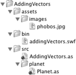
The Planet class embeds the image using the Embed metatag. Its source parameter is the path to the phobos.jpg file.
[Embed(source="../../assets/images/phobos.jpg")]
private var PlanetImage:Class;
The image is assigned to its own class, PlanetImage. You can instantiate it like this:
var planetImage:DisplayObject = new PlanetImage();
That's really all you need to do to embed and display an image in a class. However, if you want a little more control over how the image is displayed, you'll probably take it a few steps further.
To scale the image and use it as a background fill for a shape, you need to import the BitmapData and Matrix classes.
import flash.display.BitmapData;
import flash.geom.Matrix;
Both of these classes are little mini-universes of complexity in their own right, and we'll look at both of them more closely in later chapters. For now, you need to know that the BitmapData class helps display the image. The Matrix class scales, centers, and rotates it.
The drawPlanet method uses these classes to plot the image. It works by scaling the image to the value of _radius. The radius of the planet is provided by the Planet class's constructor arguments in the AddingVectors application class.
private var _planet:Planet = new Planet(100, 0x999999, 280);
The radius is 100. Its rotation is 280.
The image is then used as a bitmap fill for a circle shape (which is also the same size as the radius). The circle shape with the bitmap fill of the image of Phobos is what finally becomes the planet.
The following is the entire drawPlanet method. I've commented each line with a brief description of what it does. The best way to learn how it works is to make some small changes, recompile the AddingVectors class, and observe how your changes affect the display of the planet.
private function drawPlanet():void
{
  //1. Create a new instance of the PlanetImage class
  var planetImage:DisplayObject = new PlanetImage();

  //2. Create a BitmapData object to store the image
  var image:BitmapData = new BitmapData
   (planetImage.width, planetImage.height, false);

  //3. Draw the image, and create a new Matrix as a parameter
  image.draw(planetImage, new Matrix());

  //3a. Optionally, create a Matrix to scale (or optionally rotate) the image
  var matrix:Matrix = new Matrix();

  //3b. Find the correct scale for the image based
  on the size of the planet (its radius)
  var scale:Number = ((_radius * 2) / planetImage.width);

  //3c. Adjust the scale by 20% so that the image margins
  //are slightly cropped
  var adjustedScale:Number = scale * 1.2;

  //3d. Apply the scale amount to the matrix
  matrix.scale(adjustedScale, adjustedScale);
//3e. Center the bitmap so that its mid point is 0,0matrix.translate(-_radius, -_radius);//3f. Rotate the bitmap 280 degrees (the value of _rotation)matrix.rotate(_rotation * Math.PI / 180);//4. Draw the planet shapevar planetShape:Shape = new Shape();//Use a beginBitmapFill function to draw the bitmap onto the shape//The "true" parameter refers to whether the bitmap should be tiled//or just drawn onceplanetShape.graphics.beginBitmapFill(image, matrix, true); planetShape.graphics.drawCircle(0, 0, _radius); planetShape.graphics.endFill(); addChild(planetShape);//5. Add a bevel and drop shadow filter to the planetvar planetFilters:Array = new Array(); planetFilters = planetShape.filters; planetFilters.push ( new BevelFilter ( 4, 135, 0xFFFFFF, 0.50, 0x000000, 0.50, 4, 4 ) ); planetFilters.push(new DropShadowFilter(4, 135, 0x000000, 0.35, 4, 4)); planetShape.filters = planetFilters; }
As you can see, it's a lot of code, but you do have very fine control over how the image is displayed.
Here's a cheat sheet of all the important formulas used in this chapter.
To create a vector, you need two points: a point called A and a point called B. Both points have x and y values.
vx = b.x – a.x;
vy = b.y – a.y ;
When you have vx and vy values, you have a vector.
The magnitude (m) of a vector tells you how long the vector is. It's the distance between point A and point B.
m = Math.sqrt(vx * vx + vy * vy);
This is formula is the Pythagorean theorem.
Find a vector's angle (in degrees):
angle = Math.atan2(vy, vx) * 180 / Math.PI;
If you know only a vector's angle and magnitude, you can find its vx and vy values like this:
vx = m * Math.cos(angle);
vy = m * Math.sin(angle);
Normals are vectors that are exactly perpendicular (at 90 degrees) to the main vector. Find the left normal (lx) like this:
lx = vy;
ly = -vx;
Find the right normal (rx) like this:
rx = -vy;
ry = vx;
The left and right normals start at the base of the main vector and extend outward. That means that their start points (point A) will always be the same as the main vector's start point. You can find their point B coordinates like this:
leftNormal.b.x =  v1.a.x + lx;
leftNormal.b.y = v1.a.y + ly;

rightNormal.b.x =  v1.a.x + rx;
rightNormal.b.y = v1.a.y + ry;
Unit vectors are the smallest size that a vector can be, while still retaining the vector's direction. Normalized unit vectors are represented by the variable names dx and dy. Find them like this:
dx = vx / m;
dy = vy / m;
If you have a unit vector, you can scale it to any size. Multiply the dx and dy values by any amount.
scaledVector_Vx = dx * multiplier;
scaledVector_Vy = dy * multiplier;
To create a gravity effect between a spaceship and a round planet, follow this procedure:
Create a vector between the ship and the planet with values that are updated each frame.
shipToPlanet_Vx = planet.x – spaceShip.x;
shipToPlanet_Vy = planet.y – spaceShip.y;
Find its unit vector.
m = Math.sqrt
   (
     shipToPlanet_Vx * shipToPlanet_Vx
     + shipToPlanet_Vy * shipToPlanet_Vy
   );

shipToPlanet_Dx = shipToPlanet_Vx / m;
shipToPlanet_Dy = shipToPlanet_Vy / m;
Create a gravity vector by scaling the ship-to-planet vector with a small number, like 0.1.
gravity_Vx = shipToPlanet_Dx * 0.1;
gravity_Vy = shipToPlanet_Dy * 0.1;
Assign the gravity vector to the ship's
vxandvyvelocity values.spaceShip.vx += gravity_Vx; spaceShip.vy += gravity_Vy;
For gravity that weakens as the objects move farther apart, add mass to the equation.
planetMass = 5;
shipMass = 1;

gravity_Vx = shipToPlanet_Dx * (planetMass * shipMass) / m;
gravity_Vy = shipToPlanet_Dy * (planetMass * shipMass) / m;
The dot product tells you whether vectors are pointing in the same direction.
dp = v1.vx * v2.dx + v1.vy * v2.dy;
If the dot product is positive, the vectors point in the same direction. If it's negative, they point in opposite directions.
A vector's projection is the shadow of the vector on another vector. The projection is itself a new vector. First, find the dot product of the vector you want to project (v1) and the vector that will be the surface for the projection (v2).
dp = v1.vx * v2.dx + v1.vy * v2.dy;
Next, multiply the dot product by the surface vector's (v2's) dx and dy values.
projection_Vx = dotProduct *  v2.dx;
projection_Vy = dotProduct *  v2.dy;
The result is the new projection vector. It's the shadow of v1 on v2.
Here's the procedure for using a vector to define an environmental boundary:
Create a vector to use as an environmental boundary. This will be vector
v2.Create a vector between a game object (like the center of a space ship) and
v2's point A. This will be vectorv3.Find the dot product of
v3andv2'sleft normal (v2.ln).dp = v3.vx * v2.ln.dx + v3.vy * v2.ln.dy;
If the dot product is less than zero, you know that the game object has crossed with the environmental boundary (v2).
Find the dot product between v3 and v2.ln, as shown in the previous section. The game object needs a motion vector called v1. Multiply the absolute value of the dot product by v1's unit vector. This produces a collision vector.
collisionForce_Vx = v1.dx * Math.abs(dp);
collisionForce_Vy = v1.dy * Math.abs(dp);
Subtract the collision vector from the game object's x and y position.
gameObject.x = gameObject.x - collisionForce_Vx;
gameObject.y = gameObject.y - collisionForce_Vy;
This gives you the exact position where the game object collides with the environmental boundary, v2.
To bounce a motion vector (v1) off a surface (v2), follow this procedure:
Find the dot product of
v1andv2.dp1 = v1.vx * v2.dx + v1.vy * v2.dy;
Project
v1ontov2.p1_Vx = dp1 * v2.dx; p1_Vy = dp1 * v2.dy;
Find the dot product of
v1andv2's normal (v2.ln).dp2 = v1.vx * v2.ln.dx + v1.vy * v2.ln.dy;
Project
v1ontov2.ln.p2_Vx = dp2 * v2.ln.dx; p2_Vy = dp2 * v2.ln.dy;
Reverse the projection on
v2's normal.p2_Vx *= −1; p2_Vy *= −1;
Add up the projections to create a new bounce vector.
bounce_Vx = p1_Vx + p2_Vx;
bounce_Vy = p1_Vy + p2_Vy;
Assign the bounce vector to a game object's velocity. This should be the same object whose motion vector (
v1) was used in the preceding steps. Use a multiplier, like 0.8, to dampen or exaggerate the bounce.gameObject.vx = bounce_Vx * 0.8; gameObject.vy = bounce_Vy * 0.8;
Follow the same steps as for bounce. p1_Vx and p1_Vy are the friction values. You can use them as is or optionally multiply them with another number, like 0.98, to gradually slow down an object.
friction_Vx = p1_Vx * 0.98 ;
friction_Vy = p1_Vy * 0.98;
Assign friction to the game object's velocity.
gameObject.vx = friction_Vx;
gameObject.vy = friction_Vy;
In this chapter, we covered one of the great black arts of game design. It's the key to understanding advanced collision detection. If you understand vectors, you have total control over the geometry of your game space. Combined with the technical efficiencies of the MVC framework and Verlet integration, it gives you a killer system to form the basis of a solid physics-based game engine.
Of course, this is just a start. I haven't gone into detail about how to use these techniques for collision detection with solid objects. But I'm sure you can see that it's not that difficult. Join a few vectors together, create a loop to check for collisions with the closest intersecting vector, and you can build polygons of any shape. However, in Chapter 4, we'll be looking at a better way to handle collision between polygons.
In the next chapter, we're going to explore collision detection between circles. We'll look at a few more classic collision-detection problems such as billiard-ball physics and how to check for collisions with multiple objects.
Until then, why not design a simple game using all the techniques from this chapter? A remake of the classic game Gravitar or Omega Race might be fun.
Have fun designing your game, and I'll meet you in Chapter 3 when you're ready!