The techniques we've looked at so far won't help with pixel-perfect collision—at least, not easily. To create environments that are malleable on the smallest pixel level, we need to tackle one more great collision-detection system every Flash game designer should know: bitmap collision.
We're going to cover many interesting topics in this chapter. You'll learn how to do the following:
Convert sprites and movie clips to bitmaps.
Figure out if two bitmap objects are colliding.
Separate colliding bitmaps to create a solid collision boundary.
Build concave and convex bitmap environments for game objects.
Create a mini-map for a huge, scrolling environment.
Interactively cut holes into bitmaps to destroy parts of the environment.
And if we're going to create environments that can be destroyed, we need something to destroy them with. We're going to a build a pair of objects with wide application for games: a lander spacecraft that is typical of many side-scrolling sci-fi action games and a rotating gun turret that fires bullets (a video-game staple!)
Of course, bitmap collision involves bitmaps, so we need to start with what bitmaps are and why we need to use them.
The two main ways that computers create images are by using vector graphics and bitmap graphics.
All the graphics that we've used in this book so far have used vector drawing techniques. Vector graphics are made by plotting points and drawing connecting lines or curves between those points. When I first started using Flash, it was billed as a vector graphics animation tool, and although it's far more than that in its current form, it's still great for making vector art.
Note
Vector graphics are not the same as the mathematicalEuclidean vectors that we've been using in the previous chapters. Vector graphics are actually made using Euclidean vectors, but this is something that is largely hidden by the software that makes the graphics.
If you ever did a connect-the-dots puzzle as a child, you already know how vector graphics work. The computer knows where point A is and where point B is, and it knows that it must draw a line between them. Those connecting lines are the vectors. Vectors can make any shape, like stars or spaceships, just by joining a lot of points together. If you have complex shapes, like butterflies, the points are very close together and the lines between them are very short. Curves are handled with a mathematical formula, usually for a Bezier curve.
Vector graphics are handy because the only information stored about them is the minimum math required to plot the shape's points. This means that vector graphic file sizes tend to be very small. They contain just a few x and y coordinates, with perhaps the formula for a Bezier curve or two.
Because they just exist as mathematical formulae, vector graphics can be scaled to any size without losing detail. If you have a small vector image of a butterfly the size of your palm, you can scale it to the size of an apartment building without losing detail or increasing the file size. Just multiply all the points equally by a big number. The numbers that make up the butterfly's points will be increased proportionately, but no new information will be added to the file. You'll end up with a huge butterfly, but the file size will be no bigger than the original.
Small file size and seamless scaling are the two big advantages of vector graphics. But they have some drawbacks as well:
Slow to render: Vector graphics are, at their heart, little mathematical formulae. Math is handled by your computer's CPU, and if the CPU is busy calculating points, it has less processing power to run other parts of your game. If you have a lot of vector graphics moving around the stage, there could be hundreds of thousands of points the CPU must calculate each frame, and that eats up a big part of your performance budget.
Lack surface detail:Vector graphics just contain information about the points that make up the corners of the shape. They don't store any information about the inside area of the shape. For example, a vector graphic file of a triangle just contains the x and y coordinates of the triangle's three corners. This means that you can't change the color of individual pixels in the inner area of the triangle, because there's no way to access that information.
These weak areas of vector graphics are where bitmap graphics show their strength.
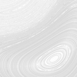
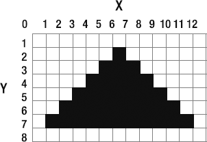
Bitmaps are rectangular grids made up of rows and columns of single pixels. (They're a "map" of "bits.") Each pixel in the grid contains a color, and by putting the right colors next to each other in the right cells in the grid, bitmaps create shapes. If vector graphics are connect-the-dots, then bitmap graphics are paint-by-numbers. Figure 5-1 shows how vectors and bitmaps represent the same shape differently.
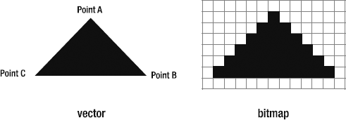
Figure 5.1. A vector graphic represents the triangle as points. A bitmap graphic represents it as a grid of pixels.
Each pixel in a bitmap graphic can be accessed and changed, and this means that you have fine control over the color of even the smallest pixel. All digital photographs are bitmaps because this surface detail is essential for photographs.
Because bitmaps don't need to calculate points, they don't have any mathematical overhead that drains CPU power from your game. But bitmaps have their own drawbacks:
Lack information: Bitmaps are clueless: All they know is the height and width of their grid, and the color information for each pixel in the grid. They don't know anything about the kind of image or shape those pixels represent.
Don't scale well:Because they don't understand their content, they can't be scaled. You can certainly try, but if you do, things get ugly, fast. The bitmap will mindlessly balloon the size of each pixel so that you end up with a terribly blocky, pixelated image. This might be cool for retro-style games, but not for almost everything else.
Use a lot of memory: The vector triangle in Figure 5-1 will have a very small file size because the only information that's stored is its three corner points, the fill color, and a calculation—four pieces of data and a simple formula that explains how to connect the points together. On the other hand, the bitmap triangle must store the color information of every single pixel in the grid. It's an 8-by-13 grid, totaling 104 bits of data to store. That makes it about 26 times bigger than the vector graphic. The bitmap is essentially spending on memory what it saves on CPU power.
But the fact that you can access individual pixels of a bitmap makes up for all these shortcomings. It means you can do accurate collision detection between irregularly shaped objects. It also means you can control single pixels or groups of pixels inside shapes. Using bitmaps opens up realms of possibilities for our games that would be nearly impossible with vector graphics alone.
In AS3.0, a bitmap is a DisplayObject, just like the MovieClip, Sprite, and shape classes. Unlike those other classes, however, a single bitmap is split between two separate classes:
The
BitmapDataclass stores all the bitmap information. It contains the grid and the color of each pixel in the grid. You can think of it as a data file or array full of numbers.The
Bitmapclass displays theBitmapDatainformation on the stage. It's the bitmap image that you can see.
To create and use a single bitmap, you work with both of these classes together.
The reason for splitting bitmaps into two classes is the same reason we've been splitting our game objects into model and view classes. If you can separate the data from the display of that data, you have much more control and flexibility.BitmapData is the model class, and Bitmap is the view class. You'll see how useful this separation is when it comes to building a mini-map for a big scrolling environment later in this chapter.
To use bitmaps in your games, you have three options:
Import a bitmap image, such as a digital photograph. For example, in Chapter 2, we imported and displayed the image of Mars's moon, Phobos, in the gravity demonstration.
Create a new bitmap from scratch using pure AS3.0 code.
Create a bitmap object from an already existing
Shape, Sprite, orMovieClipobject.
After you have your bitmaps in your games, the next step is dealing with collisions between them.
In this chapter's source files, you'll find a folder called BitmapCollision. Run the SWF, and you'll see two stars on the stage. You can move one of the stars around the stage with the mouse. If any part of the stars touch, they register a collision in the status box, as shown in Figure 5-2. The collision detection is perfect, no matter which sides or parts of the shapes are touching.
Can you imagine the brain-melting math involved if you attempted this kind of collision detection using the SAT, as in the previous chapter? I get queasy just thinking about. The amazing thing is that this collision detection is done using just one method:
bitmapData.hitTest
There's no math at all!
Let's see how this works.
To use bitmapData.hitTest, both collision objects must be bitmaps. The BitmapCollision application class has a method called makeStar that draws the stars using the drawing API techniques we covered in Chapter 1. It creates them first as vector graphics using the Shape class. It then uses those shapes to create Bitmap and BitmapData objects. Those objects are then returned to the main part of the program and used in the collision.
I know that's a bit difficult to absorb all at once, so let's go through the code. First, create the star objects.
//Star 1 (player's star)private var _s1:Object = makeStar();//Star 2private var _s2:Object = makeStar();
The stars,_s1 and _s2, are typed as Object. Creating the stars as Object types means that a single star can contain both the Bitmap and BitmapData objects. This shortcut simplifies the code a bit.
The makeStar method draws each star, and returns it as Bitmap and BitmapData. The star shape is first drawn as a vector object, and then turned into a bitmap. Here's the abridged version of the method:
private function makeStar():Object
{
  //Create the starShape vector graphic
  var starShape:Shape = new Shape();

  //... draw the star using the standard drawing API

  //Create the BitmapData to store the star graphic
  var starBitmapData:BitmapData = new BitmapData(200, 200, true, 0);

  //Draw the vector star shape into the BitmapData
  starBitmapData.draw(starShape);

  //Use the BitmapData to create the Bitmap image of
  //the star that will be visible on the stage
  var starBitmap:Bitmap = new Bitmap(starBitmapData);

  //Create the star object to return to the caller.
  //The star object contains both the BitmapData and the Bitmap
  var star:Object = new Object;
  star.bitmapData = starBitmapData;
  star.bitmap = starBitmap;
  star.shape = starShape;

  return star;
}
The star is first drawn as a vector graphic using the same drawing API methods that we've used to draw all the graphic elements in the book so far. But we need to convert the star into a bitmap so we can use pixel-perfect bitmap collision.
First, we create a BitmapData object to store the bitmap information. This creates an empty grid of pixels that is the same height and width as the original star vector graphic.
var starBitmapData:BitmapData = new BitmapData(200, 200, true, 0);
The first two parameters are the height and width of the grid: 200 by 200. The third parameter, true, means that the bitmap will have areas of alpha transparency. This is very important, because it allows us to use transparent areas to define the edges of the shape. This will be crucial for our pixel-perfect collision system to work properly.
The last parameter is 0. That's the fill color. Zero here means that any areas of the bitmap that don't have a defined color should be madetransparent. Again, this is very important for our collision system to work. However, you could use any fill color you like. If you used 0x000000, for example, the fill color would be black. The result in this example would be that the gray star would be enclosed in a black square. This could be useful in some cases, as you'll when we build a mini-map for a scrolling environment later in this chapter.
Now that we have a blank BitmapData object, we need to copy the star shape into it. The draw method does this.
starBitmapData.draw(starShape);
This is like taking a snapshot or photocopy of the star. BitmapData's draw method looks at the starShape and figures out the pixel positions and colors on the grid it needs to switch on to create a pixel map of the star.
Note
The draw method has many other parameters that you can set to fine-tune how the shape is drawn into the bitmap, and you'll find details in Adobe's online AS3 documentation, ActionScript 3.0 Language and Components Reference. In the examples later in this chapter, we'll look at some of these in much greater detail, but for now, this basic format will serve you well.
Next, we use BitmapData to create the Bitmap display object.
var starBitmap:Bitmap = new Bitmap(starBitmapData);
The starBitmap is the actual, visual bitmap image that will be displayed on the stage. It looks exactly like the original vector shape, but it has been converted into pure pixels.
Now that we've made the BitmapData and Bitmap objects, we need to get them back to the rest of the program. The simplest way to do this is to wrap them up into a single Object, and return that Object to themethod's caller.
var star:Object = new Object;
star.bitmapData = starBitmapData;
star.bitmap = starBitmap;
star.shape = starShape;

return star;
We now have our star bitmaps, so we can use them to do bitmap collision. This is done inside an ENTER_FRAME loop.
private function enterFrameHandler(event:Event):void
{
//Make the star follow the mouse
_s1.bitmap.x = stage.mouseX - 100;
_s1.bitmap.y = stage.mouseY - 100;

if(_s1.bitmapData.hitTest
    (
      new point(_s1.bitmap.x, _s1.bitmap.y),
        255,
        _s2.bitmap,
        new Point(_s2.bitmap.x, _s2.bitmap.y),
        255
      )
    )
  {
    _collision = "true";
  }
  else
  {
    _collision = "false";
  }

  //Update the status box
  _statusBox.text = "BITMAP COLLISION:";
  _statusBox.text += "
" + "COLLISION: " + _collision;
}
When bitmaps are created, their registration point is the top-left corner of the grid, as shown in Figure 5-3. This is important to remember. That means that we need to find the center of the bitmap by working down and across from that top-left corner. This bit of code determines the bitmap's center point:
bitmapCenter_X = bitmap.x + bitmap.width * 0.5;
bitmapCenter_Y = bitmap.y + bitmap.height * 0.5;
This is unlike all of the other game objects we've created in the book so far, which have been positioned directly in the center of their containing sprites. I did this so that the calculations are a little more intuitive to work out. Nothing is stopping you from centering a bitmap so that its center point has an x/y position of 0, but it doesn't make bitmaps happy. Some versions of Flash Player produce glitchy bitmap displays if the x and y position values of bitmaps contain negative numbers. It also makes some other bitmap calculations more confusing than they need to be. For these reasons, I'm going to keep the registration point at the top-left corner for all the bitmaps in the next few chapters. Keep this in mind when you look at any code that involves the width, height, or center points of bitmaps. That's why, in the code from BitmapCollision, the star bitmap is centered to the mouse's position like this:
_s1.bitmap.x = stage.mouseX - 100;
_s1.bitmap.y = stage.mouseY - 100;
The star's size is 200 by 200 pixels. To center it over the mouse, its top-left corner must be 100 pixels above and to the left of the mouse's position.
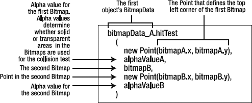
There's a magic formula for bitmap collision with the BitmapData.hitTest method. This is it:
bitmapData_A.hitTest
  (
    new Point(bitmapA.x, bitmapA.y),
    alphaValueA,
    bitmapB,
    new Point(bitmapB.x, bitmapB.y),
    alphaValueB
  )
I know, it's a rat's nest to look at! Figure 5-4 is diagram that decodes what's going on for you. When you get a bit of practice using it, you'll see that it's not as bad as it looks at first. You'll be using this same standard format over and over again. The formula contains a lot of information, but it's all really helpful. (The line breaks are just to help make the code a bit more readable, so, if you want to, you can keep everything on one really long line.)
hitTest is a method of the BitmapData class. Here are a few things you need to know about its parameters:
The point for the first bitmap should define its top-left corner. However, it can be any point. You don't need to use the x and y position of the bitmap. In these first few example files, the game objects'
xPosandyPosvalues from their model classes are used, which is typical. But in the examples later in this chapter, you'll see how useful it can be to use different values.The second object doesn't need to be a
Bitmapobject. It can also be aPointor aRectangleobject. If you want pixel-perfect collision, then it should be aBitmapobject. But if you don't need as much accuracy,PointandRectangleobjects are faster to process. You'll see how this works when we look at destroying things, near the end of the chapter. If the second object isn't aBitmapobject, you don't need to include the secondPointobject.The alpha values determine the "solid" parts of the bitmap. If the value is 255, completely opaque (solid) parts of the bitmap are used for the collision test. A value of 0 means that completely transparent areas are used for testing. You can use any value between 0 and 255 to define points of semitransparency to be used for the collision test.
Don't worry if you feel like that's a lot of information right now. For most games, it's unlikely that you'll need to modify any of the parameters from what we've used in this example. Copy and paste with glee!
Pixel-perfect collision without any math? Is it too good to be true?
Sadly, yes! As helpful as bitmap collision can be, it comes at a very high price:
It's dreadfully slow.
Collision? What's a collision?
Bitmaps have no information about the shapes they're testing. They figure out which parts of the bitmap they need to test by methodically comparing every pixel from bitmap A against every other pixel in bitmap B. They just throw them all against a wall and see which of them stick. For example, if you're testing two 100-by-100 bitmaps, each bitmap has 10,000 pixels that must be checked against 10,000 pixels in the other bitmap. Thankfully, this is done by super-optimized C++ code running in Flash Player, and it takes many shortcuts. But it's still hugely taxing. If you have any more than a small handful of objects using bitmap collision in your game, the frame rate will drop dramatically.
Note
Programmers refer to the technique of trying every possible combination to solve a problem by the very colorful term brute force. Usually you want to avoid brute-force checking because it's so extremely inefficient. But sometimes it's the only way. And other times, brute force can actually be faster, if it the alternative solution involves doing a lot of very complex, CPU-intensive calculations.
Also, our poor clueless bitmaps have absolutely no information to give us about the collision that happens. Because there's no mathematical information about the shapes, there's no way to find out by how much the shapes have intersected, the side of the shape where the collision happened, or the angle of the collision.
These are serious problems. The performance hit alone means that bitmap collision detection should only ever be a last resort in your games. Still, it's undeniably useful for complex shapes, and it's essential in some situations. So let's see how we can make it work.
All collision-detection systems must have a clear collision boundary. You need to know where and by how much the objects have intersected so that you can separate them and send them on their merry way. If your shapes are defined by vectors, you have detailed information that you can use to do this. Chapters 2, 3, and 4 were proof of that.
As you've learned, bitmaps don't have any information about their content except pixel positions and colors. Without any mathematical information about the colliding shapes, how can we possibly do the kind of separation and collision reaction that we've been doing with vectors over the past few chapters? Easy—we use vectors!
In the chapter files, you'll find a folder called BlockMovement. Run the SWF, and you'll see something that looks very much like the previous example. But in this version, the stars don't overlap when they collide. They remain cleanly separated the entire time, no matter where you move the mouse, as shown in Figure 5-5.
Here's the ENTER_FRAME loop from the BlockMovement application class that does this:

Figure 5.5. Use a bit of simple vector math to keep the shapes perfectly separated when they collide.
private function enterFrameHandler(event:Event):void
{
   _s1.bitmap.x = stage.mouseX - 100;
   _s1.bitmap.y = stage.mouseY - 100;

   //Distance vector between the stars
   var v0:VectorModel
     = new VectorModel
       (
        _s1.bitmap.x,
        _s1.bitmap.y,
        _s2.bitmap.x,
        _s2.bitmap.y
       );

  //Use a while loop to figure out if the stars are touching
  while
    (
      _s1.bitmapData.hitTest
        (
          new Point(_s1.bitmap.x, _s1.bitmap.y),
          255,
          _s2.bitmap,
          new Point(_s2.bitmap.x, _s2.bitmap.y),
          255
        )
      )
  {
    //Separate _s1 by 1 unit vector until
    //it is no longer touching _s2
    _s1.bitmap.x -= v0.dx;
    _s1.bitmap.y -= v0.dy;
  }
}
That's all there is to it! Let's see how it works:
The first thing the code does is to create a distance vector between the two stars.
var v0:VectorModel
     = new VectorModel
       (
        _s1.bitmap.x,
        _s1.bitmap.y,
        _s2.bitmap.x,
        _s2.bitmap.y
       );
Next, it does a hitTest collision check inside a while loop.
while
  (
    _s1.bitmapData.hitTest
      (
        new Point(_s1.bitmap.x, _s1.bitmap.y),
        255,
        _s2.bitmap,
        new Point(_s2.bitmap.x, _s2.bitmap.y),
        255
      )
    )
{...
If you haven't used a while loop before, don't worry, it's very easy to use. The loop runs for as long as the condition in the parentheses is true:
while(this condition is true)
{
  ...run this code
}
In this case, the condition is true if the two bitmaps are touching. That means you can understand the logic of the while loop like this:
while(the two bitmaps are touching)
{
  ...push the stars apart
}
The actual code looks more confusing than this because the unavoidably wordy hitTest method is inside the while loop's conditional statement. But take a careful look at it, and you'll see that its structure is no more complex than the pseudo code. I've used some custom formatting to make it a little more readable.
The code that runs inside the while loop is very simple.
_s1.bitmap.x -= v0.dx;
_s1.bitmap.y -= v0.dy;
All it does is push the stars out of the collision by a tiny bit. When the shapes no longer touch, the while loop quits.
How much is "a tiny bit"? It's the value of the distance vector's dx and dy values. In case you've forgotten, the dx and dy values are unit vectors. They're the smallest units that a vector can be.
The while loop does this so quickly that even if it needs to run 200 loops before it separates the shapes, you'll never notice. This all happens in one frame, and quicker than the blink of an eye. Only the end result is displayed on the stage, so you never see the separation at work. This is another example of brute force, but a while loop does this sort of thing very efficiently. It has a minimal impact on performance if used wisely and sparingly. Yay, while loop!
Figure 5-6 is a slow-motion view of the loop so that you can clearly see what it's doing over the duration of one frame.
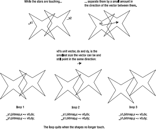
Figure 5.6. Use a bit of simple vector math to keep the shapes perfectly separated when they collide.
Now aren't you glad that you spent all that time learning about vectors? Vectors are central to almost every advanced game-design technique, and they have plenty more tricks up their sleeves.
Now for the warning: while loops are dangerous! If you use a while loop, you must make sure that the condition it checks for eventually becomes true. If it doesn't, the loop will run forever, and Flash Player will hang. In fact, if you play around with the blockMovement SWF long enough, you can probably make it hang, and you may need to force Flash Player to quit. "Bhwahahaha!" laughs the evil Flash game designer!
Don't look so shocked; there's an easy solution! We can modify the code slightly so that we can guarantee that the while loop eventually quits. An extra if statement and loop counter variable will help us out. Here's the solution:
//Distance vector between the starsvar v0:VectorModel = new VectorModel ( _s1.bitmap.x, _s1.bitmap.y, _s2.bitmap.x, _s2.bitmap.y );//Use a while loop to figure out if the stars are touching,//but limit the number of times the loop runs by//using a counter variable and incrementing it by "1" each loopvar loopCounter:int = 0; while (loopCounter++ != 200) {//An if statement inside the while loop//checks for a collisionif ( _s1.bitmapData.hitTest ( new Point(_s1.bitmap.x, _s1.bitmap.y), 255, _s2.bitmap, new Point(_s2.bitmap.x, _s2.bitmap.y), 255 ) ) {//Separate _s1 by 1 unit vector until//it is no longer touching _s2_s1.bitmap.x -= v0.dx; _s1.bitmap.y -= v0.dy; } }
You'll find a working example of this code in the SafeBlockMovement folder. In this version of the code, the loop will run for a maximum of 200 times.
while (loopCounter++ != 200)
{...
The loopCounter variable is incremented directly in the conditional statement itself. Yes, I know that's a bit sneaky, but it works great! The while loop is now guaranteed to quit after 200 loops, whether or not the hitTest method returns true. This is a fail-safe way to make sure that there's no danger of an infinite loop.
The work of checking for a collision is done by the while loop's nested if statement. If it finds a collision, it will move the shape out of the collision by a maximum of 200 increments.
For this to work in a game, you need to make sure the loop will run enough times to separate the shapes. That means that the value of loopCounter shouldn't be less than the maximum velocity at which you expect your objects to be traveling. For example, if a game spaceship is traveling at 15 pixels per second and hits an asteroid, your loop will need to run up to 15 times to make sure that it resolves the collision on that frame. If it doesn't, it will finish resolving it on the next frame, and you'll see the spaceship blip through the asteroid slightly.
When I tested this example, I found that I had to run the loop up to 200 times each frame because the shapes are very large and I was moving the mouse quickly. For most games, however, between 10 and 20 loops should be just fine. If your velocities have limits, this solution will work flawlessly. Although you want your loops to run as few times as possible, while loops are very efficient and will be the least of your performance worries.
You now have all the basics of bitmap collision detection down, and you'll be happy to know it doesn't get any more difficult than this. Yes, I know, I've said that before, but this time I mean it! The next step is to find out how to apply these techniques in practical ways to games.
There are three basic bitmap collision-detection strategies that will serve you well for all types of games:
Convex shapes: When your shapes are roundish or squarish with a solid center, like the star shapes in the previous example.
Surfaces: When the collision is from only one side, like a wall at the side of the stage or the ground at the bottom of the stage.
Concave shapes: When the shapes have a hollow center, like a cave.
Over the next pages, we'll tour all these strategies in real-live game contexts.
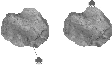
In the chapter's source files, find the Asteroid folder and run the SWF. You'll see a small Lunar Lander-style spacecraft that you can fly around the stage with the arrow keys. The lander, as its name implies, can land anywhere on the asteroid. I've made the vector between the lander and asteroid visible so that you can more easily understand the relationship between them.
Note
In all the examples in this chapter and the next, I haven't used any filters on the display objects. I've omitted them so that the bitmap edges are more clearly defined. This makes testing and debugging easier because you can clearly see how accurate the collision is. Feel free to add filters like drop shadows and bevel effects on bitmaps in your own games if they don't negatively affect performance.
The collision detection and reaction work in the same way as the previous example with the two stars. When the shapes collide, the lander is separated incrementally from the asteroid in the direction of the vector using a while loop. That's not new.
What is new is that the lander is being pulled to the bottom of the stage by gravity, and it also uses variable velocity—it has vx and vy values. For the collision reaction to be accurate, we need to compensate for the values of these new variables.
But first, let's look at how the asteroid and lander bitmaps were created.
If you're curious about how the lander works, take a peek in the com.friendsofed.gameElements.lunarLander package. It's just a variation of the player control systems you've seen before, so there's won't be any surprises.
Like the other game objects, it's rendered as a Sprite object. To use bitmap collision, we must turn it into a Bitmap object.
Note
If your game involves bitmap collision, and your objects don't need any of the features of Sprite or MovieClip objects, always create them natively as bitmaps in their view classes. Converting from a sprite to a bitmap is just an extra, unnecessary step that you should avoid.
I've broken this rule in many examples in this book for two reasons:
∞ To show you how to turn sprites into bitmaps. Sometimes it's extremely useful to be able to do this, and the performance hit may be negligible.
∞ To make sure that the
BitmapandBitmapDataclasses are completely exposed in the application classes, which is very useful to see while you're still learning.
But don't follow my bad example in your own games!
The lander has a model and view class, just like the other game objects in previous chapters. To turn it into a bitmap, send its model and view to the createBitmap method.
var landerBitmap:Object = createBitmap(_lander, _lander_View);
The createBitmap method will return an Object that contains the BitmapData and Bitmap objects. You can access those objects like this:
landerBitmap.bitmap
landerBitmap.bitmapData
The createBitmap method is near the end of the Asteroid application class.
private function createBitmap
  (model:AVerletModel, view:AVerletView):Object
{
  //Create the BitmapData and Bitmap objects based
 //on the lander's model and view
   var bitmapData:BitmapData
     = new BitmapData(model.width, model.height, true, 0);
   bitmapData.draw(view);
   var bitmap:Bitmap = new Bitmap(bitmapData);

   //Create the object to return to the caller
   var bitmapObject:Object = new Object;
   bitmapObject.bitmapData = bitmapData;
   bitmapObject.bitmap = bitmap;

   return bitmapObject;
 }
This method does what the heart of the makeStar method did in the previous example. Can you see how neatly the model matches the BitmapData and the view matches the Bitmap?
Note
Because Bitmap objects have their registration points at the top corner, we need to adjust the screen wrapping code to compensate for this with a special StageBoundaries.wrapBitmap method.
StageBoundaries.wrapBitmap(_lander, stage);The com.friendsofed.utils package also contains special bitmap methods for stopping and bouncing objects at the stage edges. You can use them like this:
StageBoundaries.stopBitmap(_lander, stage);StageBoundaries.bounceBitmap(_lander, stage);The bitmap of the lander is created every frame and is just used for the collision check. It's not added to the stage. The image of the lander that you see on the stage is the vector shape created by the lander's view class. This demonstrates how you can display vector graphics on the stage and just use matching bitmaps for behind-the-scenes collision detection.
The asteroid is a PNG image with alpha transparency. The alpha transparency is important because it's the contrast between the transparent and opaque parts of the image that defines the asteroid's shape.
I dropped the PNG image into the project's images folder:
Asteroidassetsimagesasteroid.png
PNG images are bitmap images. But we can't just use them as is. We need to import them into our program and then copy them into a BitmapData class. This makes them readable by AS3.0.
The following steps outline how to import the asteroid PNG image into the program. I've abridged a lot of the code to avoid repeating material that you should know all too well by now. Make sure to check the complete code in the source files to see it all in its proper context.
The image is embedded in the class definition using the
Embedmetatag. A class calledAsteroidImageis used to contain the image. Remember that in an odd quirk in AS3.0 syntax, the class that contains the image must come directly after theEmbedtag.public class Asteroid extends Sprite {//...//Variables required to display the asteroid bitmapprivate var _asteroidBitmap:Bitmap; private var _asteroidBitmapData:BitmapData;//Embed the image of the asteroid using a relative path to the PNG image//Create a class to store the image[Embed(source="../assets/images/asteroid.png")] private var AsteroidImage:Class;In the
Asteroidconstructor, a new instance of theAsteroidImageclass is created.public function Asteroid():void {//...var asteroidImage:DisplayObject = new AsteroidImage();asteroidImagemust be typed as aDisplayObjectThis is a bit confusing because it's obviously an instance ofAsteroidImage. The problem is that theAsteroidImageclass won't be available to the compiler when it tries to compile the SWF. If you try to type it asAsteroidImage, you'll get the error "Type was not found or was not a compile-time constant: AsteroidImage." This just means that the compiler doesn't know what theAsteroidImageclass is, and it doesn't know where to look for it. Because theAsteroidImageclass is created in the class definition, it's hidden to the compiler. This is a little technical nuisance, but easily handled. Just use the more generalDisplayObject, and all will be well.Use the
asteroidImageinstance to create the asteroid'sBitmapDataand draw the PNG image into it._asteroidBitmapData = new BitmapData(asteroidImage.width, asteroidImage.height, true, 0); _asteroidBitmapData.draw(asteroidImage);
This code should be starting to look quite familiar to you by now.
Finally, create the
Bitmapobject, add it to the stage, and position it._asteroidBitmap = new Bitmap(_asteroidBitmapData); addChild(_asteroidBitmap); _asteroidBitmap.x = 200; _asteroidBitmap.y = 100;
Via two completely different routes, we now have two bitmaps that we can use for collision detection. This is where the fun starts!
The collision system is essentially the same as the collision between the two stars in the earlier example. There's a vector between the lander and the asteroid, which is used to separate the shapes when they collide. Here's the code from the enterFrameHandler that does this:
//The distance vector between the lander and the asteroid_v0.update ( _lander.xPos + _lander.width * 0.5, _lander.yPos + _lander.height * 0.5, _asteroidBitmap.x + _asteroidBitmap.width * 0.5, _asteroidBitmap.y + _asteroidBitmap.height * 0.5 );//Check for a collisionvar loopCounter:int = 0; while (loopCounter++ != 10) { if(landerBitmap.bitmapData.hitTest ( new Point(_lander.xPos, _lander.yPos), 255, _asteroidBitmap, new Point(_asteroidBitmap.x, _asteroidBitmap.y), 255 ) ) {//Switch off gravity_lander.gravity_Vy = 0;//Move the lander out of the collision in the direction//of the distance vector_lander.setX = _lander.xPos - _v0.dx; _lander.setY = _lander.yPos - _v0.dy; _lander.vx = 0; _lander.vy = 0; } else { break; } }
For a precise-looking collision, the code switches off the lander's gravity and set its velocity to 0. If this isn't done, the lander will appear to wobble slightly when it's resting on the asteroid. This is because the forces that are pushing and pulling it are not quite equal.
If we switch gravity off when the lander is on the asteroid, we need to switch it back on again when it leaves. But there's a problem: when the lander is "resting on the asteroid," it's actually not touching the asteroid any more. It's just slightly above it.
Remember that the while loop pushes the lander and asteroid apart. The loop quits when they're no longer touching each other. That means that you can't run the same collision test to find out if the lander is actually on the asteroid, because it will always return false. The loop has done its job and separated the objects perfectly. The lander and asteroid will be directly adjacent to each other, but they won't overlap by even 1 pixel. The problem is that because they're completely separated, we have no way to detect when the lander is resting on the asteroid.
To solve this, we need to run a second collision check that tests to see if there is any ground directly below the lander. It checks to see if 1 pixel below the lander is in contact with the asteroid. If it is, then we know the lander is still "on the asteroid." If there's no ground directly below it, then we know the lander isn't in contact with the ground, and we can switch gravity back on again.
This will be easier for you understand if you can visualize it before you look at the code. Figure 5-8 illustrates the logic of what we want to accomplish.
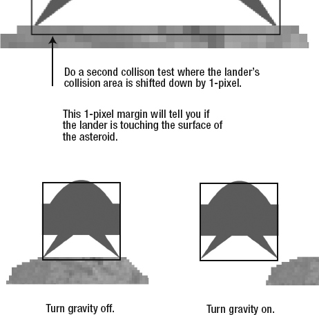
The code for this second collision test is saying, "If an area 1 pixel below the lander isn't touching the asteroid, turn gravity on."
Here's what it looks like:
if(!landerBitmap.bitmapData.hitTest
     (
       new Point(_lander.xPos, _lander.yPos + 1),
       255,
       _asteroidBitmap,
       new Point(_asteroidBitmap.x, _asteroidBitmap.y),
       255
     )
   )
 {
   _lander.gravity_Vy = 0.1;
 }
Note that it checks whether a collision is not happening.
if(!...
The + 1 is highlighted in the code so that you can clearly see where it shifts the collision area down by a pixel.
new Point(_lander.xPos, _lander.yPos + 1),In environments where game objects rest on steep surfaces, you will need a bit more clearance. You'll be able tell this if the object appears to wobble slightly when it should be resting. If that's the case, use +2, +3, +4—keep increasing that number until the wobble disappears.
There's one amazing side effect to this technique. The asteroid is a convex object, but you can use the same technique to check for collisions with concave objects. A "cave" is a perfect example of a concave object. Take a look at Figure 5-9 for an example of what I mean.
You can see in Figure 5-9 that there's a vector between the center of the cave and the lander. In the asteroid example, that same vector was used to push the asteroid and lander apart. However, inside the cave, the lander can fly around, and it's stopped when it bumps into the ground or walls, just as you would expect. This effect exactly inverts what was happening with the asteroid.
The collision technique is exactly the same. The small difference is that, instead of pushing the objects apart, it's pulling the objects apart. The direction of the vector has been reversed. The only change that needs to be made to the code to accomplish this is to change the minus sign to a plus sign, in these two lines of code:
_lander.setX = _lander.xPos+_v0.dx; _lander.setY = _lander.yPos+_v0.dy;
Isn't that effortless?
This will work as long as the concave environment is enclosed on four sides. It won't work if you want the lander to fly around the cave entrance to the outer wall. I'll explain why and provide a solution to such a situation in the "Concave shapes" section ahead.
You'll find a full working example of this in the Crater folder in the chapter's source files.

A very common requirement for game objects is to move about and interact with an uneven ground surface, like one with hills or rocks. This is very easy to implement using bitmap collision. In fact, the code is much simpler than the previous code.
We've been doing a lot of traveling through the empty reaches of deep space over the past few chapters. What can I say? It's a big universe out there! But now our space travelers have spotted a nearby planet and are going to take the lander down for a closer look.
Run the PlanetSurface SWF, and you'll see a scene that looks like Figure 5-10. When you land the lander on the surface, you can use the left and right arrow keys to drive it up and down the hills. It moves smoothly and evenly over the hilly surface in a very natural way. If you approach a hill with enough speed, you can even stylishly coast over its lip and "get some air," like a skateboarder going over a ramp.
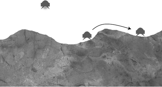
The technique used to separate the lander from the planet surface is almost identical to the techniques we used in the previous example. But it's simpler, because the collision can only ever happen on the y axis. That means we don't need to plot a distance vector. When the objects collide, we just push the lander directly up on the y axis until it's free of the collision.
Here's the section in the enterFrameHandler that handles the collision. I've highlighted the line of code that pushes the lander up and out of the collision.
var loopCounter:int = 0;
 while (loopCounter++ != 10)
 {
   if(landerBitmap.bitmapData.hitTest
       (
         new Point(_lander.xPos, _lander.yPos),
         255,
         _planetSurfaceBitmap,
         new Point
           (_planetSurfaceBitmap.x, _planetSurfaceBitmap.y),
         255
       )
     )
   {
     //Switch off gravity
     _lander.gravity_Vy = 0;
//Move the lander out of the collision on the y axis
_lander.setY = _lander.yPos - 1;
_lander.vy = 0;
}
else
{
break;
}
}Again, we need to switch gravity back on again if the lander isn't touching the ground.
if(!landerBitmap.bitmapData.hitTest
     (
       new Point(_lander.xPos, _lander.yPos + 1),
       255,
       _planetSurfaceBitmap,
       new Point(_planetSurfaceBitmap.x, _planetSurfaceBitmap.y),
       255
     )
   )
 {
   _lander.gravity_Vy = 0.1;
 }
This bit of code is identical to the previous example.
Note
If you want the lander to struggle up the sides of hills, as if battling the tug of gravity, just multiply its vy by a fractional number when it's moving up. This is the same technique we looked at for handling slopes in the polygon environment case study near the end of Chapter 4.
With convex and surface strategies, you can build very complex game environments. You can use the convex strategy to build the inner walls of a maze, and the surface strategy to build its outer walls. These techniques are extremely robust. They should be the first techniques you employ to build complex environments using bitmap collision.
But there's one situation where these strategies can't help you. Imagine that the lander is flying around the asteroid and discovers that it's hollow inside. The lander enters the hollow area and flies into the very heart of the asteroid.
This is a problem for us. The convex collision strategy depends on a vector between the center of the asteroid to the center of the lander. The vector is always pushing the lander away from the asteroid's center. If the lander touches the inner surface of the asteroid's cave, it will be pushed through the cave wall to the outside of the asteroid. Figure 5-11 illustrates what will happen.
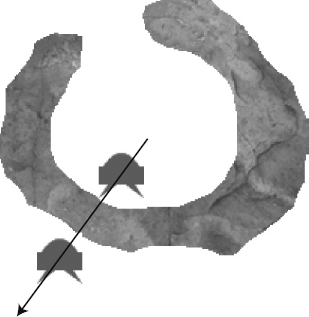
Figure 5.11. Concave shapes pose a problem. The distance vector will push the lander away from the center, through the asteroid's wall.
Obviously, this means we can't use the distance vector to separate the objects. We need another way to do it.
What are our options? Here are two contenders which, although promising, tripped over their ski poles in the qualifying round:
Figure out whether the lander is inside or outside the asteroid, and reverse the direction of the separation accordingly. This might work, but how can we determine where the outside starts and in the inside ends? It's a complex problem, and I haven't found a simple solution to it. Let me know if you think of one! Also, it might work with roundish or squarish shapes, but not complex maze structures with many inner compartments.
Use the lander's motion vector. For example, if the lander is moving forward and bumps into the asteroid's wall, we can push it back in a direction opposite to its velocity. This actually works quite well, but it breaks down if the lander gets pushed diagonally into a corner formed by two adjoining pixels. It doesn't know which way to go. It either gets stuck or flits off the screen in a blip. This isn't a robust enough solution.
And the winner is ...
Bitmaps are made up of pixels. Pixels are just little squares. Squares have only four sides. That means that when two bitmaps collide, they're only ever touching on one of four sides. If you zoomed in really closely, you would see the flat square side of the first bitmap's pixels touching the flat square side of the other bitmap's pixels.
This simplifies things a lot. It means that we can think of a collision between bitmaps as a collision between squares. That should be an easy problem to solve. All we need to do is find out which of the four sides the collision is occurring on, and push the lander away in the opposite direction.
We can't solve this problem with math, because we don't have any mathematical information about the bitmaps. And anyway, who really wants to do more math? The solution is actually straightforward, and you know part of it already.
The chapter's source files contain a working example. Find the Cave folder and run the SWF. The lander has found an entrance to a hidden cave below the planet's surface. It can fly anywhere inside it. Bump into any surface, and you'll see that the collision is clean and precise, as shown in Figure 5-12.
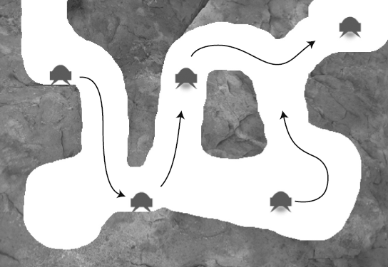
To make this work, the code does five collision checks. It first checks to see if a collision is occurring—any collision. If it finds a collision, it does four more checks to find out whether the top, bottom, left, or right side of the lander is touching the cave wall. It then pushes the lander in the opposite direction of the collision side.
The code does this by creating what I call collision boxes to do the checking. Imagine that the lander is surrounded by four boxes, and each box is checking for a collision with the cave walls, as shown in Figure 5-13. The box that finds a collision is the box that determines on which side the collision is happening. Each box extends outward from the lander by 10 pixels. They're like a beetle's feelers or antennae that can sense a collision with a wall.
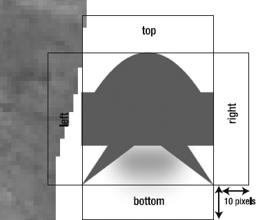
Figure 5.13. Create four collision boxes around the lander to check for collisions with the cave walls.
These collision checks run inside a while loop. The following is the entire enterFrameHandler from the Cave application class that does this collision checking.
private function enterFrameHandler(event:Event):void
 {
   //Update the lander
   _lander.update();
   StageBoundaries.wrapBitmap(_lander, stage);

   //Create the lander bitmap object
   var landerBitmap:Object = createBitmap(_lander, _lander_View);

   //Check for a collision between the lander and the cave
   var loopCounter:int = 0;
   while (loopCounter++ != 10)
   {
     if(landerBitmap.bitmapData.hitTest
         (
           new Point(_lander.xPos, _lander.yPos),
           255,
           _caveBitmap,
           new Point(_caveBitmap.x, _caveBitmap.y),
           255
         )
       )
{
//A collision was found.
//Next the code creates "collision boxes" on all
//four sides of the lander to
//find out on which side the collision is occurring
//Switch off gravity
_lander.gravity_Vy = 0;
//1. Check for a collision on the bottom
if(landerBitmap.bitmapData.hitTest
(
new Point(_lander.xPos, _lander.yPos + 10),
255,
_caveBitmap,
new Point(_caveBitmap.x, _caveBitmap.y),
255
)
)
{
//Move the lander out of the collision
_lander.setY = _lander.yPos - 1;
_lander.vy = 0;
_collisionSide = "bottom";
}
//2. Check for a collision on the top
else if
(landerBitmap.bitmapData.hitTest
(
new Point(_lander.xPos, _lander.yPos - 10),
255,
_caveBitmap,
new Point(_caveBitmap.x, _caveBitmap.y),
255
)
)
{
//Move the lander out of the collision
_lander.setY = _lander.yPos + 1;
_lander.vy = 0;
_collisionSide = "top";
}
//3. Check for a collision on the right
if(landerBitmap.bitmapData.hitTest
(
new Point(_lander.xPos + 10, _lander.yPos),
255,_caveBitmap,
new Point(_caveBitmap.x, _caveBitmap.y),
255
)
)
{
//Move the lander out of the collision
_lander.setX = _lander.xPos - 1;
_lander.vx = 0;
_collisionSide = "right";
}
//4. Check for a collision on the left
else if
(landerBitmap.bitmapData.hitTest
(
new Point(_lander.xPos - 10, _lander.yPos),
255,
_caveBitmap,
new Point(_caveBitmap.x, _caveBitmap.y),
255
)
)
{
//Collision on left
_lander.setX = _lander.xPos + 1;
_lander.vx = 0;
_collisionSide = "left";
}
}
else
{
break;
}
}
//Switch gravity back on if there is no ground below the lander.
//Adding "+1" to the lander's y position in the collision
//test is the key to making this work
if(!landerBitmap.bitmapData.hitTest
(
new Point(_lander.xPos, _lander.yPos + 1),
255,
_caveBitmap,
new Point(_caveBitmap.x, _caveBitmap.y),
255
)
){
_lander.gravity_Vy = 0.1;
}
//Update status box
_statusBox.text = "CAVE:";
_statusBox.text += "
" + "GRAVITY: " + _lander.gravity_Vy;
_statusBox.text += "
" + "COLLISION SIDE: " + _collisionSide;
}(The collisionSide variable is just used to update the status box, and isn't part of the collision system.)
This collision system works well, but it's not quite as robust as using distance vectors. If the spaces that the lander needs to fly through are too narrow, the code will get confused about the direction of the collision, and the lander will flit through the wall in the wrong direction. However, you can easily manage this with careful level design and a lot of testing. Don't make the spaces too small, and it will work just fine.
Why did I choose to extend the collision boxes by 10 pixels? This is pretty arbitrary. You might find you have to use a larger or smaller number in your games. The smaller you make the number, the narrower the spaces can be that the lander flies though, but the more prone to error the collision detection will be. You want to find the smallest possible number that still provides accurate collision detection. A value of 10 is a good starting point, but only trial and error in your own games will tell you what numbers you need to use.
Despite these quirks, this system works reliably enough. And it is so easy to implement that I've used it as the primary collision system for all the remaining examples in this chapter and the next. The collision detection is as precise and accurate as you could ever want it to be.
The other great thing about this system is that it's quick and easy to create game levels. All you need to do is draw them! Your level design can be as complex as you like, but you'll only ever need to do a collision test with one bitmap.
Note
The image of the cave in the Cave example was easy to make. Early one January morning, I was taking a walk along the frozen shores of Lake Ontario, when I spotted an interesting piece of Precambrian shale jutting up through the ice. I took a picture of it with a small pocket camera. When I got home, I loaded the image in Photoshop. It took me less than 5 minutes with my all-time-favorite tool, the Eraser, to create the cave you see in Figure 5-12. I just erased the bits or rock I didn't want and, voila, the cave was born!
I then resized the image so that it matched the stage dimensions (550 by 400) and saved it as a 32-bit PNG file. 32-bit PNG files contain alpha transparency information, which is used to define the shapes in the bitmap collision system that we're using.
This is an extremely fun way to create game levels and quickly try out new ideas.
Small caves are cool, but big caves are cooler! How big can we make the cave? This was something I had to find out. My favorite games as a child always involved exploring big environments. I loved classic cave-flyer games like Thrust, Gravitar, and Scramble, along with epic scrolling, role-playing games like the original Zelda and Final Fantasy. But I never took the slightest notice of my score. What kept me playing was just the thrill of finding out what was around the next corner.
So for the next example, I decided to use the full-size 6-megapixel photograph of the slab of Precambrian shale I used for the first Cave example. I wanted to create a really huge, scrolling underground cave for the lander to explore. And I thought, while I'm at it, why not create a GPS-style mini-map to help me find my way through this colossal environment? You can find the result in the BigCave folder. It looks like Figure 5-14.
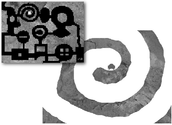
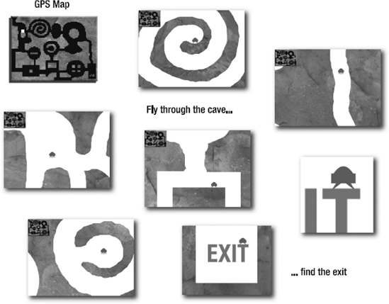
Fly the lander though the cave and try to find the exit sign. The cave scrolls as the lander moves, and a yellow dot traces its progress on a map at the top-left corner. Yes, I used the entire 6-megapixel photograph to make this cave, and yes, I had a lot of fun using the Eraser tool in Photoshop! Figure 5-15 illustrates the lander's journey through the cave.
Before you start to panic, let me reassure you that it's not complex or difficult to make this. In fact, the point of this example is to demonstrate that you don't need complex code to produce a complex-looking result. The collision techniques are identical to the previous example; I copy/pasted most of the code from that project into this one. The scrolling system is the same one I described in Foundation Game Design with Flash. The only really new thing is the mini-map, but that's created with only a few short lines of code, most of which you've already seen before. The result appears complex, but the components it's built from are routine. You'll see how easy this is in the explanations ahead.
Note
What about that big, red exit sign that the lander can bump into, fly around, and land on? It looks like it might be scarily complicated to make something like that, but it's just part of the big cave bitmap. I added the text to the photograph using Photoshop. As far as the code is concerned, that text is just part of the single bitmap shape, like the cave walls and passages. It's just more pixels—no big deal! This is a great side effect of this system: you can create radically different game levels just by editing the background image in Photoshop.
If you've read Foundation Game Design with Flash, you'll recognize this scrolling system. Four values define the inner boundary area of the stage.
private var _rightInnerBoundary:Number
   = (stage.stageWidth * 0.5) + (stage.stageWidth * 0.25);
 private var _leftInnerBoundary:Number
   = (stage.stageWidth * 0.5) - (stage.stageWidth * 0.25);
 private var _topInnerBoundary:Number
   = (stage.stageHeight * 0.5) - (stage.stageHeight * 0.25);
   private var _bottomInnerBoundary:Number
   = (stage.stageHeight * 0.5) + (stage.stageHeight * 0.25);
Note
*0.5 is the same as /2, and *0.25 is the same as /4. Flash Player processes multiplication about twice as quickly as division, so this is good optimization trick.
When the lander reaches the stage boundary, it stops moving, and the cave bitmap moves opposite to the lander's velocity.
if (_lander.xPos < _leftInnerBoundary)
 {
   _lander.setX = _leftInnerBoundary;
   _rightInnerBoundary = (stage.stageWidth * 0.5) + (stage.stageWidth * 0.25);
   _caveBitmap.x -= _lander.vx;
 }
 else if (_lander.xPos + _lander.width > _rightInnerBoundary)
 {
   _lander.setX = _rightInnerBoundary - _lander.width;
   _leftInnerBoundary = (stage.stageWidth * 0.5) - (stage.stageWidth * 0.25);
   _caveBitmap.x -= _lander.vx;
 }
 if (_lander.yPos < _topInnerBoundary)
 {
   _lander.setY = _topInnerBoundary;
   _bottomInnerBoundary
     = (stage.stageHeight * 0.5) + (stage.stageHeight * 0.25);
   _caveBitmap.y -= _lander.vy;
 }
 else if (_lander.yPos + _lander.height > _bottomInnerBoundary)
 {
   _lander.setY = _bottomInnerBoundary - _lander.height;
   _topInnerBoundary = (stage.stageHeight * 0.5) - (stage.stageHeight * 0.25);
   _caveBitmap.y -= _lander.vy;
 }
There's also an additional check that stops the cave bitmap background from moving if it reaches the edge of the cave. This bit of code also extends the inner boundary so that the lander can fly straight to the stage edges when the cave stops moving.
if (_caveBitmap.x + _caveBitmap.width < stage.stageWidth)
 {
   _caveBitmap.x = stage.stageWidth - _caveBitmap.width;
   _rightInnerBoundary = stage.stageWidth;
 }
 else if (_caveBitmap.x > 0)
 {
   _caveBitmap.x = 0;
   _leftInnerBoundary = 0;
 }
 if (_caveBitmap.y > 0)
 {
   _caveBitmap.y = 0;
   _topInnerBoundary = 0;
 }
 else if (_caveBitmap.y + _caveBitmap.height < stage.stageHeight)
 {
   _caveBitmap.y = stage.stageHeight - _caveBitmap.height;
   _bottomInnerBoundary = stage.stageHeight;
 }
It's a very effective illusion and allows for environments of any size.
Note
Chapter 8 demonstrates how to implement an alternative scrolling system using the scrollRect method.
At the beginning of this chapter, I mentioned that a bitmap is made up of two parts. The BitmapData object is the raw information that describes the size of the grid and the pixel color of every cell in that grid. The Bitmap object displays that data. I said that the reason for this is to separate the data from the display. It means that we can use the data from one bitmap to create a completely new bitmap using the same data.
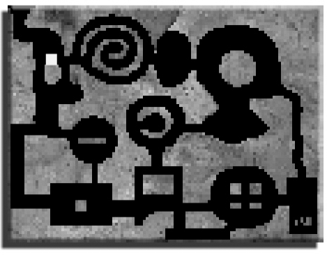
This feature pays off fabulously in helping to create the GPS mini-map. The map is just a tiny version of the huge 6-megapixel cave bitmap. All we need to do is take the cave's BitmapData and scale it to the desired size.
We first need two variables for the map's BitmapData and Bitmap objects:
private var _mapBitmapData:BitmapData;
 private var _mapBitmap:Bitmap;
The class constructor then creates these objects by taking the cave's BitmapData and scaling it down to a small size. Here's the code that does that:
//1. Determine the scale factorvar scaleFactor:Number = 0.04;//2. Determine the map's size based on//the _caveBitmap's full height and widthvar mapWidth:Number = _caveBitmapData.width * scaleFactor; var mapHeight:Number = _caveBitmapData.height * scaleFactor;//3. Create the map's BitmapData based on the scaled height and widthvar _mapBitmapData:BitmapData = new BitmapData (mapWidth, mapHeight, false, 0x000000);//4. Create a Matrix to scale the cave's BitmapData to the new sizevar scaleMatrix:Matrix = new Matrix(); scaleMatrix.scale(scaleFactor, scaleFactor);//5. Use the scaled Matrix along with the _caveBitmapData to//draw the scaled image of the cave into the _mapBitmapData_mapBitmapData.draw(_caveBitmapData, scaleMatrix);//6. Create the map's Bitmap using the new scaled _mapBitmapData_mapBitmap = new Bitmap(_mapBitmapData);
I know that you don't like the look of that Matrix object, but you'll soon see that it's not nearly as intimidating as it seems. Let's go through the code.
We first have to figure out how big we want the mini-map to be—25 times smaller is a good size.
var scaleFactor:Number = 0.04;
This value can now be applied to other values to keep the scaling consistent.
How big is "25 times smaller" in actual pixels? Let's work that out:
var mapWidth:Number = _caveBitmapData.width * scaleFactor;
 var mapHeight:Number = _caveBitmapData.height * scaleFactor;
The original cave bitmap dimensions are 2816 by 2112 pixels. The map's dimensions are worked out to be 112 by 84 pixels.
We next need to make the map's BitmapData. This line of code should be quite familiar to you, as it's how we've been creating BitmapData objects throughout this chapter. But there are two different values in the arguments, which I've highlighted here.
var _mapBitmapData:BitmapData = new BitmapData
   (mapWidth, mapHeight, false, 0x000000);
Those two values are very important:
falsemeans that there will be no areas of transparency in the bitmap.0x000000means that the bitmap's fill color will be black. Any areas of the bitmap that don't have assigned colors will be filled with black.
This gives the mini-map a nice solid, black background, which you can see in Figure 5-15. This is very different from the other bitmaps in this chapter, which were all created with transparent fill areas. It's important to remember that you can create bitmaps with any fill color you like.
Up till now, we've just been using transparent fills because they've been necessary for collision checking. An object's shape was defined by the transparent pixels that surrounded it.
If the map is 25 times smaller than the original bitmap, it will use 25 times fewer pixels. That means that we need to throw out most of the cave bitmap's pixels, but still end up with an image that looks like the original.
If you think about it, this is a pretty sophisticated problem. We're compressing each group of 25 pixels into 1 pixel. That single pixel must represent the approximate combined color values of the whole group of 25.
To do this, we need to put the cave's bitmap data through a mathematical filter. The filter must churn through all of the original data and squeeze it so that it's very small but contains correct approximations of the original pixel colors.
Luckily, AS3.0 does this for us. In fact, it has a whole class dedicated to doing mathematical filtering: the Matrix class.
Note
If reading the explanation of the Matrix class in the AS3.0 documentation makes your head swim and eyes blur over after the second sentence, don't worry! All you really need to know about the Matrix class is this:
It's used to mathematically describe the position, rotation, scaling, and skewing of display objects—in other words, their shape, size, and position.
The details of how it does these things can become complex, but they're also very specific to each task. That means you don't need to understand everything about the Matrix class right away. Just learn a little about how it works in the context that you're using it. With enough practical examples, which you'll find in this chapter and those ahead, it will start to click.
The Matrix class has a method called scale that can help us squeeze the bitmap down to size. To use it, we need to make a Matrix object.
var scaleMatrix:Matrix = new Matrix();
 scaleMatrix.scale(scaleFactor, scaleFactor);
The scale method takes two arguments: the scale factors on the x and y axes (the value of scaleFactor is 0.04, which we defined earlier). Those are the amounts by which we want to scale the object.
Now that the Matrix is loaded and ready to go, we can use it to draw the mini-map's BitmapData:
_mapBitmapData.draw(_caveBitmapData, scaleMatrix);
The BitmapData's draw method accepts a Matrix as a second argument precisely to do the job we're now asking it to do. This line of code takes the cave's bitmap and scales it down using the Matrix's scale factors. It works out how many pixels to use and finds the approximate pixel colors.
The last job is to create the map's Bitmap using the scaled _mapBitmapData.
_mapBitmap = new Bitmap(_mapBitmapData);
(The BigCave application class also gives the map a drop shadow and bevel filter to help it stand out from the background.)
It's this final _mapBitmap which is the visible mini-map that is added to the stage.
addChild(_mapBitmap);There's a fabulous bonus to the map sharing the same data as the cave. If you decide to change the design of the cave in Photoshop and resave the PNG file, the mini-map will automatically read the cave's new BitmapData and update itself accordingly. You don't need to change a single line of code or even think about it. This is one of the great advantages of separating the data from the display.
A small, yellow square marks the place on the map that matches the lander's real location in the cave. It's just a rectangle created by the drawing API. The position for the marker is found by scaling the lander's x and y positions by the same amount that the cave's bitmap is scaled. The marker's position is plotted from the top-left corner of the map.
_mapMarker.x = _mapBitmap.x + ((-_caveBitmap.x + _lander.xPos) * 0.04);
 _mapMarker.y = _mapBitmap.y + ((-_caveBitmap.y + _lander.yPos) * 0.04);
The only extra detail here is that we need to subtract the cave bitmap's position to compensate for its scrolling.
Games are usually pretty crowded, frenetic places full of enemies, treasures, and traps that can help or hinder your goal. Yes, life can be pretty hard in a video-game universe. Up until now, our little lander has had it pretty easy, wouldn't you say? Oh, if it only knew what's to come!
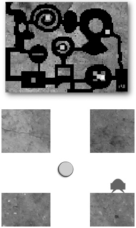
Let's take a look at how you can add objects to big, scrolling environments. In the chapter's source files, find the CaveObjects folder and run the SWF. The lander can fly around the same cave, but now the cave is populated by four mysterious green orbs. The position of the orbs is shown on the map, and they scroll along with the background, as shown in Figure 5-17.
All the objects in a scrolling environment must move at the same rate and in the same direction as the background. There are two ways that you can handle this:
Put every object that needs to scroll into a single
SpriteorMovieClipobject. That way, you need to scroll only that one container object. All the other subobjects will automatically scroll with it. The disadvantage is that whenever you want to check for a collision with any of the game objects and the player, you need to convert the objects' x and y coordinates from local to global.Scroll all the objects individually, in the same way that you scroll the background. This keeps everything in the same coordinate space, but means the scrolling won't happen automatically. You'll need to code the scrolling individually for each object or group of objects.
I don't know about you, but my brain always starts to hurt whenever I have to convert points from local to global coordinates. Also, I find it much easier to write and debug the collision code if all the objects share the same coordinate space. It just feels more natural to me. So, I've opted for the second option for the scrolling examples in this book. This is purely a personal choice. if you're more comfortable with a single scrolling background, by all means, use it. The amount of code involved in both systems is the same, and there doesn't appear to by any performance difference.
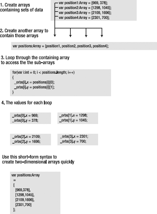
To position the green orbs in the cave, I went back to the original photograph of Precambrian shale that I was editing in Photoshop. I found the x and y coordinates of each of the four positions on the photograph where I wanted an orb to be and made a note of them. That's a total of eight numbers to keep track of, which is not much (four orbs, each with an x and y value). But it's very common for games to store and track hundreds of numbers for groups of objects like this. So rather than taking the lazy route of creating each orb and individually assigning positions to them, I'm going to show you how treat them as a single group. They all share the same properties and behave the same way, so it makes sense to work with them together as a single unit. Let's see how we can do this efficiently.
The first step is to make a little database of the orb positions. When you think of storing data, arrays immediately come to mind. We could store all the positions of the orbs in an array like this:
private var _orbPositions:Array = [969,378, 1298,1045, 2109,1696, 2301,700];
Each pair of numbers represents the x and y positions of one of the orbs.
This will work, but I'm sure you can immediately see a few problems here. One is that it's difficult to read. Even with a bit of creative spacing, it's difficult to see where one pair of numbers ends and the other begins. This might not be problem with 8 numbers, but can you imagine what it would look like with 200? It could be very difficult to isolate and debug a problem if you made a mistake entering any of the data.
Another problem is that looping becomes complicated. The great value to storing data in arrays is that you can loop though the data and perform repetitive tasks on hundred of objects with just a few lines of code. Our problem in this case is that the data is not uniform. The first number of each pair is an x position value, and the second is a y position value. That means to get or set these values on one object, the loop would need to count in twos, like this: 0, 2, 4, 6, and so on. That's fine. We could create a loop that counts in twos like this:
for(var i:int = 0; i < array.length; i += 2)
 {
   _orbs[i].x = _orbPositions[i];
   _orbs[i].y = _orbPositions[i + 1];
 }
But do you see the problem? The _orbs array that stores the objects will also skip though its values in twos. It means that only half of them will have their positions set. We could use some math get around this, but there's a simpler way.
It makes more logical sense to group each x and y value as its own single unit. Let's see how to take that approach.
First, put each pair of numbers into its own array. The array will contain only two values. That means that if you have four objects, each object's position will be stored in a single array. You'll end up with four arrays, with each array containing two numbers. The code might look something like this:
var position1:Array = [969, 378];
 var position2:Array = [1298,1045];
 var position3:Array = [2109,1696];
 var position4:Array = [2301,700];
Next, put those four position arrays into another array.
var positions:Array = [position1, position2, position3, position4];
Yes, it's just like a big fish eating a lot of smaller fish.
Now you can loop though all the array objects as you normally would. When you want to change the position of the object, you can access the subarrays.
for(var i:int = 0; i < array.length; i += 2)
 {
   _orbs[i].x = _ positions[i][0];
   _orbs[i].y = _ positions [i][1];
 }
To access the position values, you first need to locate the array in which they're stored, and then the specific x and y values. This is what the syntax looks like:
_ positions[containingArray][subArray];
or, if you prefer:
_ positions[bigFish][smallFish];
In the context of a loop, it looks like this:
_ positions[i][0];
 _ positions[i][1];
On the first loop, the preceding code will be read like this:
_ positions[position1][969];
 _ positions[position1][378];
On the second loop, it will look like this:
_ positions[position2][1298];
 _ positions[position2][1045];
Neat, huh? This is called a two-dimensional array. It's an array that contains other arrays.
There's a short form for creating two-dimensional arrays. You can create both the containing array and the subarrays in one step, like this:
private var _orbPositions:Array
   =[[969,378],[1298,1045],[2109,1696],[2301,700]];
But it's much easier to read if you format it like this:
private var _orbPositions:Array
   =
   [
     [969,378],
     [1298,1045],
     [2109,1696],
     [2301,700]
   ];
Can you see why it's called a two-dimensional array? When you format it in this way, you can clearly see that the data creates a grid. It has height and width, just like a two-dimensional shape.
This is conceptually an extremely important thing to understand. If you can "see" the shape of this data grid, it makes certain calculations in your games much easier for you to understand. You'll see how useful this is in Chapters 8 and 9, where two-dimensional arrays actually become the visual representation of the game level. But even in this example, a quick glance at that array reveals where the pairs of x and y values are. You could also think of them as two columns. This makes it very easy to edit and debug the data.
Two-dimensional arrays offer a great solution to our problem. Figure 5-18 helps you to visualize how they work.
Getting back to the example file, the positions of the orbs are now in a two-dimensional array called _orbPositions. The example file also uses another array, simply called _orbs, to store the orb shapes. The next job is to create the orbs and add them to the stage in the correct positions on the map.
The orbs are positioned with a for loop. We can assume that we need one orb for each of the four map positions. That means we can use the _orbPosition array's length property to determine how many orbs to make. This is really handy, because if we ever add more positions to the _orbPosition array, new orbs will be automatically created and added to the stage without us needing to change any other code.
for(var i:int = 0; i < _orbPositions.length; i++)
 {
   //Create the orb Shape
    var orb:Shape = new Shape();

   //...draw the shape and add filters

   //Add the shape to the _orbs array
   _orbs.push(orb);

   //Add the orb to the stage
   addChild(orb);

   //Set the initial orb positions using the values from
   //the two-dimensional array
   orb.x = _caveBitmap.x + _orbPositions[i][0];
   orb.y = _caveBitmap.y + _orbPositions[i][1];
 }
For each orb, we also need a corresponding marker to show its position on the mini-map. These map markers are just little square shapes made with the drawing API. An array called _mapMarkers stores them. We can again use the _orbPosition array's length property to figure out how many of them to make.
This is the loop that creates the map markers, pushes them into the _mapMarkers array, adds them to the stage, and positions them on the map:
for(var j:int = 0; j < _orbPositions.length; j++)
 {
   //Create the marker shape
   var mapMarker:Shape = new Shape();
   //... draw the shape
//Push the shape into the _orbMarkers array_orbMarkers.push(mapMarker);//Add the marker to the stageaddChild(mapMarker);//Position the marker on the mapmapMarker.x = _mapBitmap.x + ((-_caveBitmap.x + _orbs[j].x) * 0.04); mapMarker.y = _mapBitmap.y + ((-_caveBitmap.y + _orbs[j].y) * 0.04); }
The orbs and map markers are now on the stage in the correct positions. The next job is to scroll the orbs so that they stay synchronized with the background.
The four orbs all have fixed positions. Their positions don't change after they've been added to the stage. This makes it quite easy to scroll them.
In the enterFrameHandler, a loop uses the orbs' positions from the two-dimensional array and plots them from the top-left corner of the _caveBitmap background.
for(var i:int = 0; i < _orbs.length; i++)
 {
   _orbs[i].x = _caveBitmap.x + _orbPositions[i][0];
   _orbs[i].y = _caveBitmap.y + _orbPositions[i][1];
 }
This ensures that whenever the _caveBitmap moves, the orbs will remain fixed at the same relative position. They will correctly move in and out of the stage depending on the position of the bitmap.
For this example, this code works just fine. But what if you had a game where, after you assigned the orbs their initial position, they started moving around the cave by themselves? Maybe you've programmed them with some AI to try and hunt down the player. You would have no way of knowing where they were supposed to be relative to the background's top-left corner.
The solution is to calculate a scroll velocity. Figure out the velocity at which the background is moving, and add that velocity to the objects' positions. This allows the objects to move around within a scrolling environment.
Calculating a scroll velocity is the same as calculating velocity for any other object.
Store the scrolling background's x and y positions in temporary variables before it scrolls.
Scroll the background.
Subtract the temporary position from the new position to find the velocity.
Here's the code in the enterFrameHandler that does this (the code that scrolls the background has been abridged, but it's exactly the same as the previous example):
//Capture the current background x and y positions before//they're changed by scrollingvar temporaryX:Number = _caveBitmap.x; var temporaryY:Number = _caveBitmap.y;//...scroll the background//Calculate the scroll velocityvar scroll_Vx:Number = _caveBitmap.x - temporaryX; var scroll_Vy:Number = _caveBitmap.y - temporaryY;
The game can now use the scroll velocity to scroll the orbs:
for(var i:int = 0; i < _orbs.length; i++)
 {
    _orbs[i].x += scroll_Vx;
    _orbs[i].y += scroll_Vy;
 }
The beauty of this is that you don't need to know where any of the orbs should be. They work that out for themselves based on their current positions and the scroll velocity.
This technique is indispensable if your scrolling objects move, and you'll see it widely used in the case study in Chapter 7.
Our lander is having quite a jolly old time floating about in space caverns, but this is a video-game universe. Sooner or later, something bad is going to happen! We need to give our little lander something to defend itself with.
The perfect weapon, and video-game staple, is the multitalented rotating gun turret. If we attach one to the lander, it will be able shoot down any enemies that cross its path. You'll find an example in the Bullets folder. Run the SWF file, and you'll see that the lander has acquired a cannon. Use the mouse to rotate it and fire bullets, as shown in Figure 5-19.
The turret is a completely separate MVC system from the lander. It's a separate object and just follows the lander's position. Turrets are such useful things in games that I felt it would give me more flexibility to keep it as a separate game component.
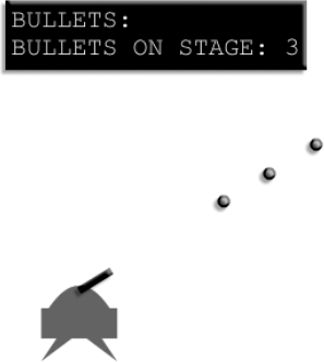
You'll find the turret's model, view, and controller in the com.friendsofed.gameElements. turret package. Its MVC components follow the same format as the lander's. The Bullets application class creates it like this:
private var _turret:TurretModel
   = new TurretModel(15, 3, 0x000000, −20, −160);
 private var _turretUIController:TurretUIController
   = new TurretUIController(_turret);
 private var _turret_View:TurretView
   = new TurretView(_turret);
 private var _turretUIView:TurretUIView
   = new TurretUIView(_turret, _turretUIController, stage);
In a big game, it would probably makes sense to create the turret as a sub-MVC system inside the lander MVC. I've created it in the application class just to more clearly expose the nuts and bolts of how it works.
The TurretView class draws a rectangle that represents the barrel of the cannon. Its middle center is at 0, and the rectangle is drawn toward the left, as shown in Figure 5-20.
_turretShape.graphics.drawRect
   (0,model.height / 2, -model.width, -model.height);
This aligns the shape accurately so that it rotates correctly according to the formula we'll use.
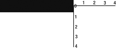
Figure 5.20. Set the barrel of the cannon so that it's aligned to the left of the shape's middle center point.
This puts it at a starting rotation position of 0 degrees. You can think of this position as lying flat on the ground.
You'll notice in the SWF that the cannon can't make a full 360-degree rotation around the lander. The rotation is constrained within a certain range. This creates the effect of the lander's hull blocking the cannon's movement, as shown in Figure 5-21.
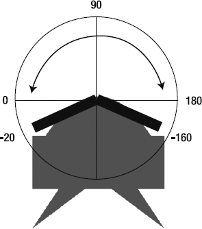
The cannon can move freely between −20 to −160 degrees, but not outside that range.
The TurretModel has constrainLeft and contrainRight properties, which can be initialized in its constructor. They are the last two arguments in the constructor method:
private var _turret:TurretModel = new TurretModel
(15, 3, 0x000000, −20, −160);The first three arguments set the cannon's width, height, and color.
To move the cannon, the TurretUIView listens for mouse movements and sends that information to the TurretUIController's processMouseMove method to figure out what should happen.
internal function processMouseMove(stage:Object):void
 {
   //Figure out the angle based on the mouse's stage position
   var angle:Number = Math.atan2
     (_model.yPos - stage.mouseY, _model.xPos - stage.mouseX);

   //Constrain angle to the top arc of the lander
   if(angle * 180 / Math.PI > _model.constrainLeft
   || angle * 180 / Math.PI < _model.constrainRight)
   {
     _model.angle = angle;
   }
 }
This is the same formula for calculating an angle of rotation using Math.atan2 described in Foundation Game Design with Flash.
The TurretModel has an angle property that it has inherited from its parent, the AVerletModel superclass. When the angle changes, AVerletModel dispatches a CHANGE event. The TurretView listens for that event, and its changeHandler updates the rotation of the turret shape.
override protected function changeHandler(event:Event):void
 {
   super.changeHandler(event);
   _turretShape.rotation = model.angle  * 180 / Math.PI;
 }
This is the same way that view classes update an object's visual position on the stage based on changing xPos and yPos values in the model. Instead of changing its x and y position, it's just changing its angle.
Figure 5-22 is a map of the turret's MVC system so you can see how it all fits together. I've removed all but the most essential code, so make sure you refer to the original source files for a complete working example. This diagram is just to help you understand the relationship between the classes.
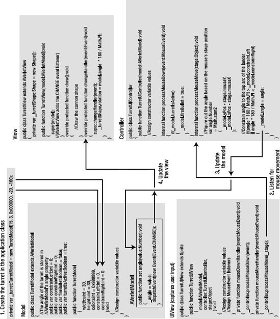
The turret doesn't actually fire any bullets. It just gives permission to the application class to add them to the stage.
The TurretModel has a Boolean variable called fireBullet, which determines whether bullets can be added to the stage. It's set to true by the turret's controller when the mouse button is clicked.
internal function processMouseDown(event:MouseEvent):void
 {
   if(_model.turretIsActive)
   {
     _model.fireBullet = true;
   }
 }
You can see how this bit of code fits into the grand scheme of things in Figure 5-22.
The Bullets application class checks whether fireBullet is true. In that case, it creates the bullets and adds them to the stage at the end of the cannon's barrel. It uses the turret's angle property and some trigonometry to find the right spot to place them. (This trigonometry is also covered in detail in Foundation Game Design with Flash.) It also gives them their initial velocity and adds the bullet model and views to arrays.
if(_turret.fireBullet == true)
 {
   //Create the bullet model and push it into the _bulletModels array
   var bulletModel:CircleModel = new CircleModel(2);
   _bulletModels.push(bulletModel);

   //Position the bullet model at the end of the turret
   //and give it an initial velocity
   bulletModel.setX = _turret.xPos - _turret.width * Math.cos(_turret.angle);
   bulletModel.setY = _turret.yPos - _turret.width * Math.sin(_turret.angle);
   bulletModel.vx = Math.cos(_turret.angle) * −10;
   bulletModel.vy = Math.sin(_turret.angle) * −10;
   bulletModel.friction = 1;


   //Add the bullet view and push it into the _bulletViews array
   var bulletView:CircleBlockView = new CircleBlockView(bulletModel);
   addChild(bulletView);
   _bulletViews.push(bulletView);

   //Reset the turret so that it can fire again
   _turret.fireBullet = false;
 }
The last thing it does is set the turret's fireBullet property to false. This prevents a bullet from firing again until the next mouse click.
The bullet models and views are now conveniently in arrays. That means we can deal with all of them just by looping through the number of bullets that have been created. The application class has the next few tasks to perform:
Call the bullets'
updatemethods so that they move across the stage.Remove the bullet views if they cross the stage boundaries. This involves removing them from the stage and splicing them from both the model and view arrays.
A single for loop takes care of both these steps.
for(var i:int = 0; i < _bulletModels.length; i++)
 {
   //Update the bullet model
   _bulletModels[i].update();

   //Remove the bullet if it crosses the stage boundary
   if(_bulletModels[i].yPos < 0
   || _bulletModels[i].yPos > stage.stageHeight
   || _bulletModels[i].xPos < 0
   || _bulletModels[i].xPos > stage.stageWidth)
   {
     _bulletModels.splice(i, 1);
     removeChild(_bulletViews[i]);
     _bulletViews.splice(i, 1);
     i--;
   }
 }
I find that it's much easier to manage adding and removing objects when these tasks are done in the application or game controller class.
Make sure you take a good look at the Bullets application class so that you can see all this code in its proper context.
What's the point of discovering new and mysterious worlds in distant corners of the galaxy if we can't destroy them? Our little lander has a new toy to play with, so we're going to let it loose and make this chapter live up to its promise!
Run the BitmapErase SWF for a taste of the trouble to come. The lander can fly around the cave and blast holes in the rock, as shown in Figure 5-23. The lander can use these holes as new routes to fly through and perch on new ledges that the holes make, as shown in Figure 5-24.
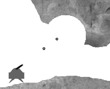
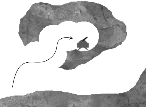
Figure 5.24. The new environment can change the game in unexpected ways. Hide from enemies or plan attacks.
Being able to interactively change the game world at the pixel level has tremendous potential in games. It means that players can use the environment to strategically solve puzzles, hide from enemies, or plan attacks. It also means that the game is different each time it's played. Terrain deformation is big topic in game design, and many action-strategy games, like Worms, make it a central part of their game engines. If you design and plan your games carefully, terrain deformation can help you create a game with unexpected outcomes that are exciting to play and replay.
Although the effect is impressive and extremely useful, terrain deformation with AS3.0 can be accomplished with only a few lines of code. Actually, it all boils down to one line.
It will be easier for you to understand the code if you know what we're asking it to do. Think of the stage as a big grid. Each pixel position on the stage represents a cell on the grid. Remember that bitmaps are also just big grids full of pixel information. In that way, they're exactly like the grid that makes up x and y stage positions. The only difference is that they also contain pixel color information.
When one of the bullets hits the bitmap, the code plots a circle onto the cave bitmap in the same place as the bullet's stage position. The circle is then erased from the cave bitmap. That leaves a gaping hole in the cave the same size as the circle. Because those pixels have been erased, they're no longer involved in the bitmap collision check, and the lander can fly through the hole.
Collision detection between the bullets and the cave bitmap uses the same Bitmapdata.hitTest method as in previous examples. However, there's one big difference. The bullets are really small, so we don't need to bother checking whether their entire area is hitting the cave, just their center points.
The Bitmapdata.hitTest method has an option for checking bitmaps against single points. All you do is specify the second object in the collision as a Point object.
Here's the code in the BitmapErase application class that checks for a collision between the bullets and the cave (I've highlighted the important new code):
if(_caveBitmapData.hitTest
     (
       new Point(_caveBitmap.x, _caveBitmap.y),
       255,
       new Point(_bulletModels[i].xPos, _bulletModels[i].yPos)
     )
   )
 { ...
The second object is just a point. It can be any Point object. In this case, the bullet's x and y position is converted into a Point object.
Bitmap collision detection is extremely processor-intensive, so whenever you have a chance to substitute a Point for a Bitmap object, do it! It will give your game a noticeable performance boost.
You can also specify Rectangle objects as the second object in the collision. Here's an example:
if(_caveBitmapData.hitTest
     (
       new Point(_caveBitmap.x, _caveBitmap.y),
       255,
       new Rectangle(x, y, width, height)
     )
   )
 { ...
(The x and y positions refer to the top-left corner of the rectangle.)
This essentially checks for a collision between the bitmap and an object's bounding box. Rectangular bounding boxes are widely used for collision checking in games because of their speed and simplicity, and you can harness those benefits here. As with Point objects, using Rectangle objects means that your game doesn't need to process more pixel information, and that's a big performance saving. If you don't need absolute pixel-perfect collision detection, make sure you use Point and Rectangle objects every chance you get.
Just as in the previous example, the bullets are stored in two arrays: _bulletModels and _bulletViews.
Note
Now that you know about two-dimensional arrays, you could store both the model and views in the same array, following the same format we used for storing positions in the object scrolling example. This will make your code a bit more compact, but also possibly a little less readable, so I'll leave it up to you to decide whether or not to try it.
A for loop cycles through each bullet, updates it, and checks for collisions. When it finds a collision between the bullet and cave, it carves a hole in the cave bitmap. Here's all the code that does this, and I'll explain in detail how the hole is created in the section that follows.
for(var i:int = 0; i < _bulletModels.length; i++)
 {
   //Update the bullet model
   _bulletModels[i].update();

   //Check for a collision between the cave bitmap and the
   //bullet's x and y position
   if(_caveBitmapData.hitTest
(
new Point(_caveBitmap.x, _caveBitmap.y),
255,
new Point(_bulletModels[i].xPos, _bulletModels[i].yPos)
)
)
{
//Assign a radius for the circle
var radius:int = 40;
//Create a circle shape using the above radius value
var circle:Shape = makeCircle(radius);
//Create a Matrix object. The Matrix's
//"translate" method is used to
//position the circle shape in the
//right place on the cave bitmap
var matrix:Matrix = new Matrix();
matrix.translate(_bulletModels[i].xPos, _bulletModels[i].yPos);
//Redraw the cave bitmap using the
//circle shape and the matrix.
//The BlendMode.ERASE argument tells the cave's BitmapData
//to erase the circle shape at the
//position specified by the matrix
_caveBitmapData.draw(circle, matrix, null, BlendMode.ERASE);
//Remove the bullet
_bulletModels.splice(i, 1);
removeChild(_bulletViews[i]);
_bulletViews.splice(i, 1);
i--;
}
}Only five lines of code do the job of creating the hole in the bitmap. The first thing the code needs to do is create a circle shape.
var radius:int = 40;
 var circle:Shape = makeCircle(radius);
This is handled by the makeCircle method that you'll find near the end of the application class.
private function makeCircle(radius:int = 30):Shape
 {
   //Create the shape
   var shape:Shape = new Shape();
   shape.graphics.lineStyle(0);
   shape.graphics.beginFill(0xFFFFFF);
shape.graphics.drawCircle(0, 0, radius); shape.graphics.endFill(); return shape }
Its job is just to return a circle Shape object.
Realize that you can use any shape you like. I've just used circles for the sake of clarity, but in a game, you might use different shapes and vary them depending on the kind of destruction you want. (You'll see an example of this in the next section.) Also, you are not restricted to Shape objects. You can use sprites, movie clips, or other bitmaps—any display object will work. With enough time and attention to detail, you could create very realistic and intricate destruction effects.
Note
You don't want the imaginative destruction of players to cause bugs in the game, so you'll need to do a lot of testing and set limits where necessary.
The next step is to create a Matrix object that stores the position of the bullet where it hits the cave. The Matrix class has a translate method that stores x and y position values.
var matrix:Matrix = new Matrix();
 matrix.translate(_bulletModels[i].xPos, _bulletModels[i].yPos);
Again, don't let that Matrix class put you off! We need to use it so that we can communicate the position of the bullet to the bitmap. The bitmap can't read the bullet's position directly. The position must be wrapped inside a Matrix class object.
Finally, we need to redraw the cave's BitmapData with this new information.
_caveBitmapData.draw(circle, matrix, null, BlendMode.ERASE);
This is another way of saying, "Redraw the cave's bitmap, but erase a circle shape at whatever position the matrix says you should."
The null in the arguments just says that there's no ColorTransform object involved in the mix. A ColorTransform object allows you to adjust the colors of the bitmap.
And that's it! As I said, the effect is really just created by one line of code. But what a line of code it is! With a bit of imagination, you have a whole new universe of possibilities and directions that you can take your games.
I mentioned that you can use any shapes to create your destructible environment, not just circles. You'll find a working example of this in the JaggedBitmapErase folder. In this example, the lander is able to blast jagged rock shapes into the cave wall and fly through the new spaces, as shown in Figure 5-25.
Figure 5.25. Cut holes in the environment bitmap using different shapes, and randomize them for an organic effect.
The code is identical to the previous example, except that the shape is created by this new makeBrokenRock method:
private function makeBrokenRock(scaleFactor:int = 8):Shape
{
   //Create a new Vector object for the drawing coordinates
   var coordinates:Vector.<Number> = new Vector.<Number>();

   //Create the broken rock shape
   //in a 1:1 grid
   coordinates.push
     (
       0,0, 4,2, 7,0, 10,2,
       8,6, 10,10, 6,9, 4,10,
       3,9, 0,10, 2,7, 0,5,
       1,3, 0,0
     );

   //Scale to the correct size, and center the shape
   for(var i:int = 0; i < coordinates.length; i++)
   {
     //Scale the shape to the scaleFactor value
     coordinates[i] *= scaleFactor;

     //Center the shape at 0,0
     coordinates[i] -= (scaleFactor * 10) * 0.5;
   }

   //Create a Vector object for the drawing commands
   var commands:Vector.<int> = new Vector.<int>();
//1 = moveTo(), 2 = lineTo(), 3 = curveTo()commands.push(1,2,2,2,2,2,2,2,2,2,2,2,2,2);//Create the shapevar shape:Shape = new Shape(); shape.graphics.lineStyle(0); shape.graphics.beginFill(0xFFFFFF); shape.graphics.drawPath(commands, coordinates); shape.graphics.endFill(); return shape }
The coordinates for the shape are in a 10-by-10 grid.
coordinates.push
     (
     0,0, 4,2, 7,0, 10,2,
     8,6, 10,10, 6,9, 4,10,
     3,9, 0,10, 2,7, 0,5,
     1,3, 0,0
     );
Figure 5-26 illustrates this.
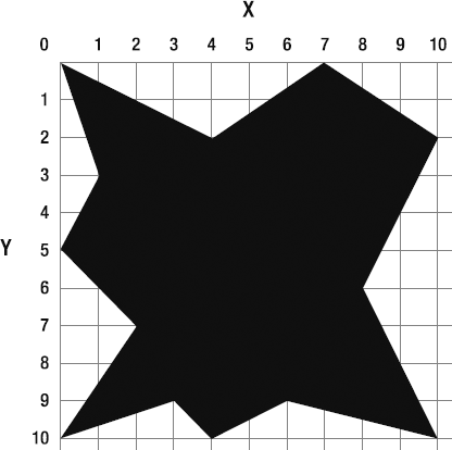
I created this shape in a 10-by-10 grid because it's a convenient size to plot the points and makes it easy to scale. The only problem is that if we used the shape as is, it would produce a 10-by-10-pixel bitmap. That's too small. The code needs to scale it up to a much larger size so that the shape will cut a sizable chunk out of the cave wall.
The makeBrokenRock method has a scaleFactor variable that's initialized with a value of 8. If we multiply all the values in the grid by 8, we'll end up with an 80-by-80-pixel shape, which is a much better size for the game. The for loop multiplies all the values in the grid by 8:
coordinates[i] *= scaleFactor;
But that's not the end of the story. We also want the shape to be centered. So the next line in the loop subtracts 40 from all the values.
coordinates[i] -= (scaleFactor * 10) * 0.5;
This pushes the shape 40 pixels to the left and 40 pixels up. It means that the center of the shape will be exactly at point 0—perfectly centered.
Note
Yes, I could have created this shape in a centered 80-by-80 grid to begin with. But it's important to demonstrate how you can scale and center a shape like this. It means you can create shapes of many different sizes just by changing the scaleFactor value.
You could create a more realistic effect by having the method randomly choose one of three or four different shapes each time the method is called, and vary the sizes slightly. This would make the effect organic and unpredictable.
Within the first few weeks of getting in to Flash game design, I had filled up every Flash message board on the Internet (the two that existed then!) with question after question about how to do pixel-perfect collision between irregular shapes. That was back in what now seems like the medieval period of Flash 4, when I was still learning ActionScript, and almost everyone else on the message boards was about as puzzled about this as I was. There were some great theories proposed, but no workable solutions. Why oh why, we lamented, did Flash not provide an easy way to check for collisions between irregular shapes?
When I finally had a chance to revisit the problem, Flash 8 had arrived, and with it most of the tools to do the kind of bitmap collision covered in this chapter. But surprisingly, it was rarely used. In the interim, not only had Flash game developers found plenty of creative work-arounds, but many of those work-arounds proved to work better for most collision problems than using bitmaps. Game developers had figured out that bounding boxes or AABB collision were perfectly adequate most of the time and, as a bonus, really fast. And if you needed circles or weird shapes, use math. Mathematical solutions, as you've seen in Chapters 2, 3, and 4, are not only fast, but give you a lot of information about the collision that you can use for things like bounce and friction.
That's still pretty much all true. All things being equal, doing bitmap collision testing is slow. Game designers will do whatever they can to squeeze any extra CPU juice out of their system, and if that means not using pixel-perfect collisions, so be it.
But pixel-perfect collision is amazing! And, as you've seen from this chapter, it allows you to achieve some effects that would be very complicated to do otherwise. For creating destructible environments or bumpy surfaces, bitmap collision testing is essential.
How slow is it? You certainly would not want to do hundreds of bitmap collision tests each frame, because Flash Player would grind to a halt. But if you use bitmap collision wisely for a limited number of objects, it's plenty fast enough for most games. Just assume that it's going to be slow, use it conservatively, do a lot of testing, and you'll be fine. In Chapter 8, I'm going to introduce broad-phase collision testing, which will help you to optimize this even further. You really shouldn't have any excuse not to use pixel-perfect collision in your games. It's great!
But enough talk; this is a book about video games, so let's blow some things up!