Chapter 4
Efficient Graphics with OpenGL ES 2.0
We have seen what OpenGL 1.0 can offer, but there is so much more to this API. In this chapter, we take a look at the cutting edge in graphics development: OpenGL ES 2.0, a subset of OpenGL. We'll start with a brief description of the most important features OpenGL ES 2.0 can offer, including shaders, GLSL, and how they affect the Android platform. Then, will take a deeper look into OpenGL ES Shading Language (GLSL) by creating a neat Android project to render a geometric shape—icosahedrons—using OpenGL ES 2.0. Let's get started.
OpenGL ES 2.0 and Android
OpenGL ES 2.0 is a set of enhancements to OpenGL ES 1.0. It emphasizes a programmable 3D graphics pipeline with the ability to create shader and program objects and the ability to write vertex and fragment shaders in the GLSL.
OpenGL ES 2.0 provides the following desirable qualities for current graphics programming:
- A wider range of precision options for use in embedded devices using shading language similar to the desktop OpenGL 2.0
- Frame Buffer Objects to simplify surface management and offer a subset of functionality from the desktop FBO
- One hundred percent backward compatible with OpenGL ES 1.x and built with the latest standards and most advanced ideas available for graphics development
Android fully implements the OpenGL ES 2.0 specification. However, the following are some caveats you should consider before using this technology to build your games:
- OpenGL ES 2.0 is not supported in all versions of Android. Thus if you are targeting the largest breath of devices out there, you should stick with OpenGL ES 1.x.
- OpenGL ES 2.0 implements the slickest ideas and technology in graphics rendering; however, that doesn't necessarily mean that the code will be better or run faster.
It does provide a desirable characteristic, nevertheless. It is designed to reduce power consumption in embedded systems such as phones, thus it could reduce your game's overall power requirements and provide more efficient graphics rendering. All in all, having a solid knowledge of OpenGL ES 2.0 is a good thing for your résumé. Chances are that if you are a graphics developer looking for a job, the very first thing you'll be asked in a job interview is your knowledge about shaders and GLSL.
Shaders
Ashader is a simple program that describes the traits of either a vertex or a pixel. At the low level, a shader defines a set of software instructions used to calculate rendering effects with a high degree of flexibility. Shaders were created to replace the traditional desktop OpenGL fixed-function pipeline that allowed only common geometry transformation and pixel-shading functions. They provide the following advantages over the traditional desktop OpenGL pipeline:
- Customized effects can be applied for rendering
- A higher degree of flexibility
- Simplicity, and higher degree of reusability
There are three basic types of shaders implemented in OpenGL ES 2.0: vertex, fragment, and geometry.
Vertex Shaders
Vertexshaders are run once for each vertex given to the GPU and transform the 3D position in virtual space to the 2D coordinate for on-screen rendering. They can manipulate properties such as position, color, and texture coordinates, but cannot create new vertices.
Fragment Shaders
Fragmentshaders (also known as pixel shaders) calculate the color of individual pixels. They are typically used for scene lighting and related effects, such as bump mapping and color toning, and are often called many times per pixel for every object that is in the corresponding space.
Geometry Shaders
Geometryshaders can add and remove vertices from a mesh. They are used to generate geometry or to add volumetric detail to existing meshes that would be too costly to process on the CPU.
GLSL
GLSL is the OpenGL ES 2.0 Shading Language for programming vertex and fragment shaders that has been adapted for embedded platforms. It is meant to work together with OpenGL ES 1.1 to minimize the cost and power consumption of embedded devices like smartphones.
TIP: OpenGL ES 2.0 removes fixed-point functionality commonly used in desktop OpenGL and replaces it with shader for power savings critical on smartphones and other embedded systems.
At the implementation level, GLSL is actually two closely-related languages: vertex shader and fragmentshader.
Vertex Shader Language (VSL)
At its simplest, VSL is a C style program to manipulate the attributes of a vertex. The following fragment defines a very simple vertex shader to set the rendering position to the position of the current vertex.
void main(void)

{

  // This is a C++ style comment

 /* This is a C style comment */

  gl_Position = gl_Vertex;

}
As we can see, the shader has a C-style syntax with main function where you simply declare GLSL instructions. In this case, we use two built-in variables:
gl_Position: Sets the position of the vertex to be renderedgl_Vertex: Contains the position of the current vertex being processed
Fragment Shader Language (FSL)
The FSL is used to change the color attributes (RGBA) of the current pixel. For example, the following fragment sets the color of the current pixel to red RGBA (1, 0, 0, 0).
void main(void)

{

   gl_FragColor = vec4(1.0, 0.0, 0.0, 0.0);

}
gl_FragColor is the built-in variable used to set the color of the current pixel. As with any programming language, GLSL provides all the things you would expect from a computer language, including:
- Variables and functions: All variables and functions must be declared before being used
- Basic types: This includes
void,bool,int,float,vec2(two-component float point vector), boolean or integer 2, 3 or 4 component vectors,22, 33, or 44 float matrices - Declaration scope: Determines where the declaration is visible; this includes global and local variables, name spaces, plus re-declarations within the same scope
- Storage qualifiers: Qualifiers specified in front of the type—pure traditional C-style—including: local variables and constants
New to GLSL, we also have:
attribute: defines the linkage between a vertex shader and OpenGL ES for per-vertex datauniform: tells that the value does not change across the primitive being processed; forms the linkage between a shader, OpenGL ES, and the applicationvarying: defines that linkage between a vertex shader and a fragment shader for interpolated data
- Parameter qualifiers: These are the qualifiers passed to the arguments of a function, including:
in: a parameter is passed into a functionout: a parameter passed back out of a function, but not initializedinout: a parameter is passed both into and out of a function
- Precision qualifiers: For floating point precision including:
highp,mediump, andlowpfor high, medium, and low precision, respectively - Variance and the invariant qualifier: These are used to handle the possibility of getting different values from the same expression in different shaders. It is possible, in independent compilation, that two identical shaders are not exactly the same when they run, in which case there are two qualifiers—invariant and varying—to prevent or allow this.
- Operators and expressions: All the common operators and expression you would expect from your typical programming language (see the following sidebar for more details)
- Many other powerful features: These include built-in angle, trigonometry, exponential, matrix, and vector functions; built-in variables, and more
Need GLSL Help?
Now let's take a look at how we can implement a shader and use it in an Android program.
Anatomy of a Shader
The anatomy of a shader is defined by the following steps:
- Create a program. The very first step is to create a shader program to be run within your main program—a program within a program, if you will.
- Load the shader. Once you create the shader, you must load it from a string variable or file.
- Attach. Next, you must attach the shader to the main program.
- Link. This step compiles the shader code and checks for syntax errors.
- Optional validation. It is always a good idea to validate the link status and handle errors appropriately.
- Enable and use. Finally, you can enable it and use it against a set of vertices.
Creating the Shader Program
To create a shader object or program, we use the glCreateShader API call. It takes as a parameter a shader type: either GL_VERTEX_SHADER or GL_FRAGMENT_SHADER for vertex or fragment respectively. glCreateShader returns a non-zero value by which it can be referenced. The following fragment creates two shaders to load a vertex, and fragment shaders to draw an icosahedron (described later in this chapter).
    int         Shader[2]

  // Create 2 shader programs

    Shader[0] = glCreateShader(GL_VERTEX_SHADER);

    Shader[1] = glCreateShader(GL_FRAGMENT_SHADER);
   // Load VertexShader: It has the GLSL code

    LoadShader((char *)VertexShader, Shader[0]);


   // Load fragment shader: FragmentShaderBlue has the GLSL code

    LoadShader((char *)FragmentShaderBlue, Shader[1]);


    // Create the program and attach the shaders & attributes

    int Program   = glCreateProgram();
We also make an API call to glCreateProgram, which creates an empty program object and returns a non-zero value by which it can be referenced. Shaders must be attached to a program. This provides a mechanism to specify the shader objects that will be linked to create a program. It also provides a means for checking the compatibility of the shaders that will be used to create a program. Next, we load it.
Loading the Shader
Ashader object is used to maintain the source code strings that define a shader. For this purpose, we can create a load function that invokes: glShaderSource and glCompileShader. glShaderSource takes as arguments the ID of the shader, the number of elements, a string containing the source code to be loaded, and an array of string lengths (NULL in this case). glCompileShader compiles the shader described by its reference ID. The following fragment describes the load function that will be used to draw the Icosahedron for an upcoming project.
// Simple function to create a shader

void LoadShader(char *Code, int ID)

{

    // Compile the shader code

    glShaderSource  (ID, 1, (const char **)&Code, NULL);

    glCompileShader (ID);


    // Verify that it worked

    int ShaderStatus;

    glGetShaderiv(ID, GL_COMPILE_STATUS, &ShaderStatus);


    // Check the compile status

    if (ShaderStatus != GL_TRUE) {

        printf("Error: Failed to compile GLSL program
");

        int Len = 1024;

        char Error[1024];

        glGetShaderInfoLog(ID, 1024, &Len, Error);

        printf(“%s
”, Error);

        exit (-1);

    }

}
As a bonus, you can also check the compilation status using the API call glGetShaderiv. It takes as arguments: a shader ID, a query constant (GL_COMPILE_STATUS, in this case, to check the compilation status), and the status of the query. If the status is not GL_TRUE, then the compilation errors can be extracted by calling glGetShaderInfoLog with the ID of the shader and a string buffer that described the nature of the error. The next step is attaching the shader to a program.
Attaching to the Shader
To attach our shader to the main program, use the API call glAttachShader. It takes as arguments the ID of the program object, to which a shader object will be attached, and the shader object that is to be attached, as shown in the following fragment.
    glAttachShader(Program, Shader[0]);

    glAttachShader(Program, Shader[1]);

    glBindAttribLocation(Program, 0, "Position");

    glBindAttribLocation(Program, 1, "Normal");
We also use glBindAttribLocation to associate a user-defined attribute variable in the program object with a generic vertex attribute index. The name of the user-defined attribute variable is passed as a null-terminated string in the last argument. This allows the developer to declare variables in the master program and bind them to variables in the shader code.
Linking the Shader Program
To use the shaders, we must link the program that contains them by calling glLinkProgram with the reference ID of the program. Behind the scenes, OpenGL will create an executable that will run on the programmable fragment processor.
    // Link

    glLinkProgram(Program);
Getting the Link Status
The status of the link operation will be stored as part of the program object's state. It is always a good idea to check for errors by getting the status of the link using glGetProgramiv, very similar to the way we checked the compilation status but using the GL_LINK_STATUS constant in this particular case. The following fragment demonstrates how to do so.
 // Validate our work thus far

    int ShaderStatus;

    glGetProgramiv(Program, GL_LINK_STATUS, &ShaderStatus);

    if (ShaderStatus != GL_TRUE) {

        printf("Error: Failed to link GLSL program
");

        int Len = 1024;

        char Error[1024];

        glGetProgramInfoLog(Program, 1024, &Len, Error);

        printf("%s
", Error);

        exit(-1);

    }
Optional: Program Validation and Status
You should always validate program objects. It helps to see if you have syntax errors in your shader code. To validate a program, use the API call glValidateProgram with the reference ID of the program. Next, call glGetProgramiv with the program validation constant GL_VALIDATE_STATUS. The result of the validation will be returned in the last argument (ShaderStatus in this case). Then, simply check the status and handle the error accordingly, as shown in the following fragment.
    glValidateProgram(Program);

    glGetProgramiv(Program, GL_VALIDATE_STATUS, &ShaderStatus);


    if (ShaderStatus != GL_TRUE) {

        printf("Error: Failed to validate GLSL program
");

        exit(-1);

    }
Finally, enable and use the program.
Enabling and Using the Program
To starts things off, use glUseProgram with the program ID to install a program object as part of a current rendering state. A program object will contain an executable that will run on the vertex processor if it contains one or more shader objects of type GL_VERTEX_SHADER that have been successfully compiled and linked.
// Enable the program

glUseProgram                (Program);

glEnableVertexAttribArray   (0);

glEnableVertexAttribArray   (1);
Remember the two local attributes (Position and Normal) we declared in the attach step? They must be enabled before they can take effect. By default, all client-side capabilities are disabled, including all generic vertex attribute arrays. If enabled, the values in the generic vertex attribute array will be accessed and used for rendering when calls are made to vertex array commands such as glDrawArrays, glDrawElements, glDrawRangeElements, glArrayElement, glMultiDrawElements, or glMultiDrawArrays.
Now let's put what we have learned so far into practice by building a neat Android project to draw an icosahedron usingshaders.
Invoking OpenGL ES 2.0 in Android
Before we jump into the Android project, there are three steps that we should keep in mind when using OpenGL ES 2.0 in Android as opposed to OpenGL ES 1.x.
- The surface view Java class must use a custom context factory to enable 2.0 rendering.
- The surface view class must use a custom
EGLConfigChooserto be able to select anEGLConfigthat supports 2.0. This is done by providing a config specification toeglChooseConfig()that has the attributeEGL10.ELG_RENDERABLE_TYPEcontaining theEGL_OPENGL_ES2_BITflag set. - The surface view class must select the surface's format, then choose an
EGLConfigthat matches it exactly (with regards to red/green/blue/alpha channels bit depths). Failure to do so will result in anEGL_BAD_MATCHerror.
Project Icosahedron
This is where we put our skills to the test with a cool Android project to draw an icosahedron using vertex and fragment shaders. The goals of the exercise are to:
- Demonstrate the use of vertex and fragment shaders using OpenGL ES 2.0.
- Demonstrate the use of hybrid activities (both Java and C++) to perform the geometry rendering. The project launcher, surface, and rendering thread will be created in Java. All OpenGL ES 2.0 rendering will be performed in C++, using JNI to glue both parts together.
- Demonstrate Android multi-touch functionality to manipulate the rotation speed (using swipes) and the zooming (using pinching) of the shape.
But before we start, let's take a look at what an icosahedron is.
Reviewing the Shape
An icosahedron is a regular polyhedron with 20 identical equilateral triangular faces, 30 edges, and 12 vertices (see Figure 4–1).

Figure 4–1. Regular icosahedron
The following Cartesian coordinates define the vertices of an icosahedron with edge-length 2, centered at the origin:
    (0, ±1, ±)

    (±1, ±, 0)

    (±, 0, ±1)
where φ = (1+√5)/2 is the golden ratio (also written asτ). Note that these vertices form five sets of three concentric, mutually orthogonal golden rectangles. In the OpenGL coordinate system, which ranges from [-1, 1] in all axes. The 12 vertices of the icosahedron are defined as the following:
// Vertex information

float PtData[][3] = {

        {0.5f, 0.0380823f, 0.028521f},

        {0.182754f, 0.285237f, 0.370816f},

        {0.222318f, -0.2413f, 0.38028f},

        {0.263663f, -0.410832f, -0.118163f},

        {0.249651f, 0.0109279f, -0.435681f},

        {0.199647f, 0.441122f, -0.133476f},

        {-0.249651f, -0.0109279f, 0.435681f},

        {-0.263663f, 0.410832f, 0.118163f},

        {-0.199647f, -0.441122f, 0.133476f},

        {-0.182754f, -0.285237f, -0.370816f},

        {-0.222318f, 0.2413f, -0.38028f},

        {-0.5f, -0.0380823f, -0.028521f},

};
The 20 triangular faces (that map to the vertices) are defined as follows:
// Face information

unsigned short FaceData[][3] = {

        {0,1,2,},

        {0,2,3,},

        {0,3,4,},

        {0,4,5,},

        {0,5,1,},

        {1,5,7,},

        {1,7,6,},

        {1,6,2,},

        {2,6,8,},

        {2,8,3,},

        {3,8,9,},

        {3,9,4,},

        {4,9,10,},

        {4,10,5,},

        {5,10,7,},

        {6,7,11,},

        {6,11,8,},

        {7,10,11,},

        {8,11,9,},

        {9,11,10,},

};
This information will be used by the shaders in our C++ program to render the scene on screen, as you'll see later on. But first, let's take a look at the project in more detail.
Tackling the Project
We'll start by creating a new Android project to host the code. Start the Eclipse Android project wizard and create a new project, as shown in Figure 4–2.

Figure 4–2. Project properties for the icosahedron
Next, perform the following steps:
- Give the application a name (anything you choose).
- Enter a package name;
com.opengl.shaderin this case. - Select a main Activity name (
ShadersActivity). - Select a minimum SDK API number (14 for Android 4) and click Finish.
Your project should look as shown in Figure 4–3.
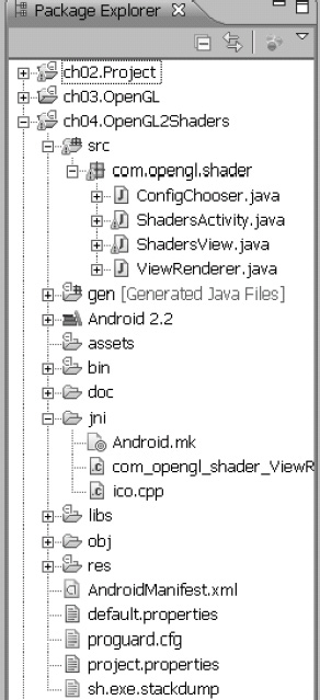
Figure 4–3. Icosahedron project
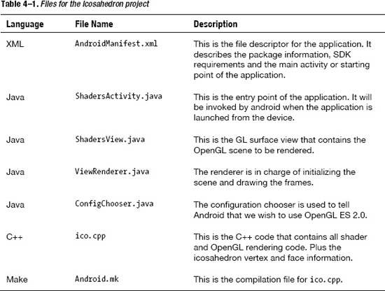
Table 4–1 lists the files that compose the project.
TIP: If you get stuck, get the source for this project is under ch04.OpenGLES2Shaders, available from the publisher.
Now let's look at the files in more detail.
Manifest
Listing 4–1 is the XML file created by the wizard. The most important thing to remember is to use the OpenGL ES 2.0 feature and set the required attribute to true.
Listing 4–1. Android Manifest for the Project
<?xml version="1.0" encoding="utf-8"?>

<manifest xmlns:android="http://schemas.android.com/apk/res/android"

    package="com.opengl.shader"

    android:versionCode="1"

    android:versionName="1.0" >


<uses-sdk

        android:minSdkVersion="14"

        android:targetSdkVersion="14" />
<uses-feature

        android:glEsVersion="2"

        android:required="true" />


<application

        android:icon="@drawable/ic_launcher"

        android:label="@string/app_name" >

<activity

            android:label="@string/app_name"

            android:name=".ShadersActivity" >

<intent-filter >

<action android:name="android.intent.action.MAIN" />

<category android:name="android.intent.category.LAUNCHER" />

</intent-filter>

</activity>

</application>

</manifest>
The next step is the main activity.
Activity
Listing 4–2 shows the main program of an Android application. It is very simple: when the application starts, the onCreate method will be invoked. Within this method, a ShadersView object is created and set as the content view. A set of arguments may be passed to the C++ layer by invoking the setrenderer method with an array of strings.
Listing 4–2. Main Application Activity
public class ShadersActivity extends Activity {

  ShadersView view;

  int width;

  int height;


  @Override

  public void onCreate(Bundle savedInstanceState) {

    super.onCreate(savedInstanceState);

      width = getWindowManager().getDefaultDisplay().getWidth();

    height = getWindowManager().getDefaultDisplay().getHeight();


    String[] args = {};


    view = new ShadersView(this);

    view.setRenderer(args, false, 0, 0);


    setContentView(view);

  }

}
Now, on to the surface view.
Surface View
The surface view is in charge of creating an OpenGL-capable, hardware-accelerated surface where objects can be drawn. The process is triggered by the setRenderer method. Because Android supports a plethora of graphics configuration, resolutions, and hardware specs, we don't know if the running device is set up to perform OpenGL ES 2.0 calls. Thus we must create a context factory class ContextFactory, which implements GLSurfaceView.EGLContextFactory. This class can then be used to tell Android that we wish to use an OpenGL ES 2.0-enabled context by giving the version as an attribute (see Listing 4–3).
int[] attrib_list = {EGL_CONTEXT_CLIENT_VERSION, 2, EGL10.EGL_NONE };

EGLContext context = egl.eglCreateContext(display, eglConfig, EGL10.EGL_NO_CONTEXT, attrib_list);
Listing 4–3. Surface View Class
public class ShadersView extends GLSurfaceView {

  private static final String TAG = "View";


  private String[] mArgs;

  private ViewRenderer mRenderer;


  public ShadersView(Context context) {

    super(context);

  }


  public void setRenderer(String[] args, boolean translucent, int depth,

      int stencil) {

    Log.d(TAG, "Setting startup args & renderer");


    mArgs = args;


    /*

     * Setup the context factory for 2.0 rendering. See ContextFactory class

     * definition below

     */

    setEGLContextFactory(new ContextFactory());


    /*

     * We need to choose an EGLConfig that matches the format of our surface

     * exactly. This is going to be done in our custom config chooser. See

     * ConfigChooser class definition below.

     */

    setEGLConfigChooser(translucent ? new ConfigChooser(8, 8, 8, 8, depth,

        stencil) : new ConfigChooser(5, 6, 5, 0, depth, stencil));


    mRenderer = new ViewRenderer();

    setRenderer(mRenderer);

  }


  private static class ContextFactory implements

      GLSurfaceView.EGLContextFactory {

    private static int EGL_CONTEXT_CLIENT_VERSION = 0x3098;
    public EGLContext createContext(EGL10 egl, EGLDisplay display,

        EGLConfig eglConfig) {

      Log.w(TAG, "creating OpenGL ES 2.0 context");


      checkEglError("Before eglCreateContext", egl);


      int[] attrib_list = { EGL_CONTEXT_CLIENT_VERSION, 2, EGL10.EGL_NONE };

      EGLContext context = egl.eglCreateContext(display, eglConfig,

          EGL10.EGL_NO_CONTEXT, attrib_list);


      checkEglError("After eglCreateContext", egl);

      return context;

    }


    public void destroyContext(EGL10 egl, EGLDisplay display,

        EGLContext context) {

      egl.eglDestroyContext(display, context);

    }

  }


  private static void checkEglError(String prompt, EGL10 egl) {

    int error;

    while ((error = egl.eglGetError()) != EGL10.EGL_SUCCESS) {

      Log.e(TAG, String.format("%s: EGL error: 0x%x", prompt, error));

    }

  }


  public void setRotationSpeed(int speed) {

    ViewRenderer.setRotationSpeed(speed);

  }


  public void setVideoSize(final int width, final int height) {

    queueEvent(new Runnable() {

      public void run() {

        ViewRenderer.initialize(width, height);

      }

    });

  }

}
ShadersView is also in charge of the following:
- Choosing an
EGLConfigthat matches the format of the surface exactly. This is going to be done in the configuration chooser class later on. For example, the following fragment tells the surface to use an RGB565 configuration with a depth and stencil size.setEGLConfigChooser( new ConfigChooser(5, 6, 5, 0, depth, stencil) ); - Creating a setting for the surface renderer.
mRenderer = new ViewRenderer();

setRenderer(mRenderer);
Surface Renderer
The surface renderer (ViewRenderer) contains the following methods, which trigger on different stages of the surface life cycle, as shown in Listing 4–4:
onSurfaceCreated: fires only once when the surface is first createdonSurfaceChanged: may fire multiple times whenever a surface change occurs; for example, when the device is rotatedonDrawFrame: fires many times by the rendering thread when a frame is drawn
Listing 4–4. Surface Renderer
public class ViewRenderer implements GLSurfaceView.Renderer {


  private static final String TAG = "ViewRenderer";


  // native initializer

  native static void initialize(int width, int height);

  // native draw frame

  native static void drawFrame(int ticks);

  // native set rotation speed

  native static void setRotationSpeed(int speed);


  static {

    System.loadLibrary("icosahedron");

  }


  @Override

  public void onDrawFrame(GL10 arg0) {

    // Log.d(TAG, "onDrawFrame");

    int ticks = (int) System.currentTimeMillis();


    drawFrame(ticks);

  }


  @Override

  public void onSurfaceChanged(GL10 arg0, int w, int h) {

    Log.d(TAG, "onSurfaceChanged w=" + w + " h=" + h);

    initialize(w, h);

  }


  @Override

  public void onSurfaceCreated(GL10 arg0, EGLConfig conf) {

    Log.d(TAG, "onSurfaceCreated " + conf);

  }

}

Viewrenderer also declares the native C++ methods that will be invoked to initialize the scene, draw a frame, and set the rotation speed of the object. It also loads the native C++ library libicosahedron.so which contains the C++ implementations of these methods:

native static void initialize(int width, int height);

native static void drawFrame(int ticks);

native static void setRotationSpeed(int speed);

static {
        System.loadLibrary("icosahedron");

}
Next comes the critical GLES 2.0 configuration chooser.
OpenGL ES 2.0 Configuration Chooser
The configuration chooser is critical to select an EGLConfig that supports OpenGL ES 2.0. ConfigChooser implements the Android interface GLSurfaceView.EGLConfigChooser and must receive a configuration spec with the attribute EGL10.ELG_RENDERABLE_TYPE containing the EGL_OPENGL_ES2_BIT flag. With this information, it queries the display for all available configurations (see Listing 4–5).
// Get the number of minimally matching EGL configurations

int[] num_config = new int[1];

egl.eglChooseConfig(display, s_configAttribs2, null, 0, num_config);


int numConfigs = num_config[0];

// Allocate then read the array of minimally matching EGL configs

EGLConfig[] configs = new EGLConfig[numConfigs];

egl.eglChooseConfig(display, s_configAttribs2, configs, numConfigs, num_config);
With this information, it chooses the best configuration that matches the original configuration spec.
Listing 4–5. Configuration Chooser
class ConfigChooser implements GLSurfaceView.EGLConfigChooser {

  private static final String TAG = "ConfigChooser";

  private boolean DEBUG = false;


  public ConfigChooser(int r, int g, int b, int a, int depth, int stencil) {

    mRedSize = r;

    mGreenSize = g;

    mBlueSize = b;

    mAlphaSize = a;

    mDepthSize = depth;

    mStencilSize = stencil;

  }


  /*

   * This EGL config specification is used to specify 2.0 rendering. We use a

   * minimum size of 4 bits for red/green/blue, but will perform actual matching

   * in chooseConfig() below.

   */

  private static int EGL_OPENGL_ES2_BIT = 4;

  private static int[] s_configAttribs2 = { EGL10.EGL_RED_SIZE, 4,

      EGL10.EGL_GREEN_SIZE, 4, EGL10.EGL_BLUE_SIZE, 4,

      EGL10.EGL_RENDERABLE_TYPE, EGL_OPENGL_ES2_BIT, EGL10.EGL_NONE };


  public EGLConfig chooseConfig(EGL10 egl, EGLDisplay display) {


    /*

     * Get the number of minimally matching EGL configurations

     */

    int[] num_config = new int[1];
    egl.eglChooseConfig(display, s_configAttribs2, null, 0, num_config);


    int numConfigs = num_config[0];


    if (numConfigs <= 0) {

      throw new IllegalArgumentException("No configs match configSpec");

    }


    /*

     * Allocate then read the array of minimally matching EGL configs

     */

    EGLConfig[] configs = new EGLConfig[numConfigs];

    egl.eglChooseConfig(display, s_configAttribs2, configs, numConfigs,

        num_config);


    if (DEBUG) {

      printConfigs(egl, display, configs);

    }

    /*

     * Now return the "best" one

     */

    return chooseConfig(egl, display, configs);

  }


  public EGLConfig chooseConfig(EGL10 egl, EGLDisplay display,

      EGLConfig[] configs) {

    for (EGLConfig config : configs) {

      int d = findConfigAttrib(egl, display, config, EGL10.EGL_DEPTH_SIZE,

          0);

      int s = findConfigAttrib(egl, display, config,

          EGL10.EGL_STENCIL_SIZE, 0);


      // We need at least mDepthSize and mStencilSize bits

      if (d < mDepthSize || s < mStencilSize)

        continue;


      // We want an *exact* match for red/green/blue/alpha

      int r = findConfigAttrib(egl, display, config, EGL10.EGL_RED_SIZE, 0);

      int g = findConfigAttrib(egl, display, config, EGL10.EGL_GREEN_SIZE,

          0);

      int b = findConfigAttrib(egl, display, config, EGL10.EGL_BLUE_SIZE,

          0);

      int a = findConfigAttrib(egl, display, config, EGL10.EGL_ALPHA_SIZE,

          0);


      if (r == mRedSize && g == mGreenSize && b == mBlueSize

&& a == mAlphaSize)

        return config;

    }

    return null;

  }


  private int findConfigAttrib(EGL10 egl, EGLDisplay display,

      EGLConfig config, int attribute, int defaultValue) {


    if (egl.eglGetConfigAttrib(display, config, attribute, mValue)) {

      return mValue[0];
    }

    return defaultValue;

  }


  private void printConfigs(EGL10 egl, EGLDisplay display,

      EGLConfig[] configs) {

    int numConfigs = configs.length;

    Log.w(TAG, String.format("%d configurations", numConfigs));

    for (int i = 0; i < numConfigs; i++) {

      Log.w(TAG, String.format("Configuration %d:
", i));

      printConfig(egl, display, configs[i]);

    }

  }


  private void printConfig(EGL10 egl, EGLDisplay display, EGLConfig config) {

     // code removed for simplicity

    }

  }


  // Subclasses can adjust these values:

  protected int mRedSize;

  protected int mGreenSize;

  protected int mBlueSize;

  protected int mAlphaSize;

  protected int mDepthSize;

  protected int mStencilSize;

  private int[] mValue = new int[1];

}
That will take care of the Java side of things; now let's shift gears to the C++ rendering. Table 4-1 described the native side of the project (contained in the ico.cppfile), which is the last piece of the puzzle. This file is in charge of the JNI function implementation; it also contains the source of the shaders, plus scene initialization and rendering. Let's take a look.
Native Icosahedron
The Java native functions declared in ViewRenderer.java are implemented in C++ using the syntax shown in Listing 4–6.
Listing 4–6. C++ Native Functions for the Project
// Java

static {

System.loadLibrary("icosahedron");

}

native static void initialize(int width, int height);

native static void drawFrame(int ticks);

native static void setRotationSpeed(int speed);


// C++

extern "C" {

 JNIEXPORT void JNICALL Java_com_opengl_shader_ViewRenderer_initialize

  (JNIEnv * env, jclass cls, jint w, jint h)

 {

        Init(w,h);
 }


 JNIEXPORT void JNICALL Java_com_opengl_shader_ViewRenderer_drawFrame

  (JNIEnv * env, jclass cls, jint ticks)

 {

        Display(ticks);

 }


 JNIEXPORT void JNICALL Java_com_opengl_shader_ViewRenderer_setRotationSpeed

  (JNIEnv * env, jclass cls, jint val)

 {

        doSetRotationSpeed((double)val);

 }

}
We have the following three C++ functions:
Init: to initialize the sceneDisplay: to draw a frame of the scenedoSetRotationSpeed: to set the rotation speed
Before we look at the implementations, we must create the two shader programs, vertex and fragment, which will be used to draw the icosahedron.
Project Shaders
Listing 4–7 declares the two shader programs that will be used to compute the position and color of the vertices and the faces of the icosahedron.
Listing 4–7. Shaders Used in the Icosahedron Project
// vertex Shader

attribute vec3 Position;

attribute vec3 Normal;


uniform mat4 Proj;

uniform mat4 Model;


varying vec3 NormVec;

varying vec3 LighVec;


void main(void)
{

vec4 Pos = Model * vec4(Position, 1.0);

gl_Position = Proj * Pos;

NormVec     = (Model * vec4(Normal,0.0)).xyz;

LighVec     = -Pos.xyz;

}


// Fragment Shader

varying highp vec3 NormVec;

varying highp vec3 LighVec;


void main(void)
{

  lowp vec3 Color = vec3(1.0, 0.0, 0.0);

  mediump vec3 Norm  = normalize(NormVec);

  mediump vec3 Light = normalize(LighVec);

  mediump float Diffuse = dot(Norm, Light);

  gl_FragColor = vec4(Color * (max(Diffuse, 0.0) * 0.6 + 0.4), 1.0);

}
Scene Initialization
The scene initialization in Listing 4–8 performs the following steps:
- It creates two shader programs, vertex and fragment.
Shader[0] = glCreateShader(GL_VERTEX_SHADER);

Shader[1] = glCreateShader(GL_FRAGMENT_SHADER); - It loads the vertex shader.
LoadShader((char *)VertexShader, Shader[0]); - It loads the fragment shader. Note that
VertexShaderandFragmentShaderRedare two strings describing the shaders in Listing 3–28 from Chapter 3.LoadShader((char *)FragmentShaderRed, Shader[1]); - It creates the program and attaches the shaders and attributes.
Program   = glCreateProgram();

glAttachShader(Program, Shader[0]);

glAttachShader(Program, Shader[1]); - It attaches the attributes or variables (
PositionandNormal) used by the master and shader programs to manipulate the vertex and face information of the icosahedron.glBindAttribLocation(Program, 0, "Position");
glBindAttribLocation(Program, 1, "Normal"); - It links the program using its program ID:
glLinkProgram(Program). - It validates the program status by querying the status using the
GL_VALIDATE_STATUSconstant.glValidateProgram(Program);
glGetProgramiv(Program, GL_VALIDATE_STATUS, &ShaderStatus);
if (ShaderStatus != GL_TRUE) {
// handle error
} - It enables the program and attributes:
Position (0)andNormal (1).glUseProgram (Program);
glEnableVertexAttribArray (0);
glEnableVertexAttribArray (1);
Listing 4–8. Scene Initialization
int Init(int w, int h) {
width = w;
height = h;
LOGD("Init: w=%d h=%d", width, height);
// Vertex shader from Listing 3–28
const char VertexShader[] = " ... ";
// Fragment Shader (see Listing 3–28)
const char FragmentShaderRed[] = "...";
// Create 2 shader programs
Shader[0] = glCreateShader(GL_VERTEX_SHADER);
Shader[1] = glCreateShader(GL_FRAGMENT_SHADER);
LoadShader((char *) VertexShader, Shader[0]);
if (id == 2) {
LoadShader((char *) FragmentShaderBlue, Shader[1]);
} else {
LoadShader((char *) FragmentShaderRed, Shader[1]);
}
// Create the program and attach the shaders & attributes
Program = glCreateProgram();
glAttachShader(Program, Shader[0]);
glAttachShader(Program, Shader[1]);
glBindAttribLocation(Program, 0, "Position");

glBindAttribLocation(Program, 1, "Normal");
// Link
glLinkProgram(Program);
// Validate our work thus far
int ShaderStatus;
glGetProgramiv(Program, GL_LINK_STATUS, &ShaderStatus);
if (ShaderStatus != GL_TRUE) {
LOGE("Error: Failed to link GLSL program
");
int Len = 1024;
char Error[1024];
glGetProgramInfoLog(Program, 1024, &Len, Error);
LOGE(Error);
exit(-1);
}
glValidateProgram(Program);
glGetProgramiv(Program, GL_VALIDATE_STATUS, &ShaderStatus);
if (ShaderStatus != GL_TRUE) {
LOGE("Error: Failed to validate GLSL program
");
exit(-1);
  }


  // Enable the program

  glUseProgram(Program);

  glEnableVertexAttribArray(0);

  glEnableVertexAttribArray(1);


  // Setup the Projection matrix

  Persp(Proj, 70.0f, 0.1f, 200.0f);


  // Retrieve our uniforms

  iProj = glGetUniformLocation(Program, "Proj");

  iModel = glGetUniformLocation(Program, "Model");


  // Basic GL setup

  glClearColor(0.0, 0.0, 0.0, 1.0);

  glEnable ( GL_CULL_FACE);

  glCullFace ( GL_BACK);


  return GL_TRUE;

}
Initialization is the first step and it is performed only once. Next, we tackle rendering.
Scene Rendering
Scene rendering is performed multiple times when a frame is to be drawn. Listing 4–9 defines the Display C++ function.
Listing 4–9. Scene Rendering
void Display(int time) {

  // Clear the screen

  glClear ( GL_COLOR_BUFFER_BIT);


  float Model[4][4];


  memset(Model, 0, sizeof(Model));


  // Setup the Proj so that the object rotates around the Y axis

  // We'll also translate it appropriately to Display

  Model[0][0] = cosf(Angle);

  Model[1][1] = 1.0f;

  Model[2][0] = sinf(Angle);

  Model[0][2] = -sinf(Angle);

  Model[2][2] = cos(Angle);

  Model[3][2] = -1.0f;

  Model[3][3] = 1.0f;


  // Constantly rotate the object as a function of time

  int ticks = time;

  int thisTicks = ticks - lastTicks; // note delta time

  if (thisTicks > 200)

    thisTicks = 200; // throttling

  Angle += ((float) thisTicks) * RotationSpeed; // apply animation

  lastTicks = ticks; // note for next loop
    // Vertex information

    float PtData[][3] = {

    // see source (removed for simplicity)

    };


    // Face information

    unsigned short FaceData[][3] = {

    // see source (removed for simplicity)

    };


  // Draw the icosahedron

  glUseProgram(Program);

  glUniformMatrix4fv(iProj, 1, false, (const float *) &Proj[0][0]);

  glUniformMatrix4fv(iModel, 1, false, (const float *) &Model[0][0]);


  glVertexAttribPointer(0, 3, GL_FLOAT, 0, 0, &PtData[0][0]);

  glVertexAttribPointer(1, 3, GL_FLOAT, GL_TRUE, 0, &PtData[0][0]);


  glDrawElements(GL_TRIANGLES, sizeof(FaceData) / sizeof(unsigned short),

  GL_UNSIGNED_SHORT, &FaceData[0][0]);

}
The Display C++ function performs the following steps:
- It clears the screen with
glClear (GL_COLOR_BUFFER_BIT);. - It creates a model matrix float Model[4][4] to setup a projection so that the object rotates around the Y axis. It also translates it appropriately to display.
- It then constantly rotates the object as a function of time.
- It enables the program with
glUseProgram (Program);. - It binds the shader attributes
Position (iProj)andNormal (iModel)to the projection (Proj) andModelmatrices.glUniformMatrix4fv (iProj, 1, false, (const float *)&Proj[0][0]);
glUniformMatrix4fv (iModel, 1, false, (const float *)&Model[0][0]); - It sets the icosahedron vertex information with
    glVertexAttribPointer   (0, 3, GL_FLOAT, 0, 0, &PtData[0][0]);

glVertexAttribPointer (1, 3, GL_FLOAT, GL_TRUE, 0, &PtData[0][0]); - Finally, it draws the icosahedron using the
GL_TRIANGLESand the face information array described at the beginning of the project.glDrawElements (GL_TRIANGLES, sizeof(FaceData) / sizeof(unsigned short),
GL_UNSIGNED_SHORT, &FaceData[0][0]);
Setting the Rotation Speed
The rotation speed function in Listing 4–10 is a bonus C++ call that will be used in the next section to change the rotation speed whenever a finger is swiped in the display. To do so, it updates a global variable RotationSpeed, which is, in turn, used by the Display function to update the angle of the Model matrix used by the shaders. Because RotationSpeed is read by multiple threads, it is declared as volatile that tells the compiler to always re-read from memory when used.
Listing 4–10. Setting the Rotation Speed
volatile float RotationSpeed = 0.001f; // Rotation speed of our object

void doSetRotationSpeed(double val)

{

    // we'll make the slowest it goes 0.001, and

    // the fastest 0.01

    double slowest = -0.005;

    double fastest = 0.005;

    double range = fastest - slowest;

    RotationSpeed = (float)(slowest + ((range*val)/100.0f));

}
This takes care of the C++ side of things. As a bonus, let's add swipe and pinch zooming functionality with Android's multi-touch APIs.
Adding Swipe and Multi-Touch Pinch for Zooming
As a bonus, this section describes how to use the Android multi-touch APIs to increase the rotation speed of the icosahedron by:
- Increasing the speed whenever finger-swiped to the right, or decrease it when swiping to the left. The rotation will switch from left to right whenever a threshold value is reached.
- Zooming the shape in or out whenever pinching inward or outward with two fingers.
Listing 4–11 describes the additions to the ShadersActivity class to perform such tasks.
Listing 4–11. Swipe and Pinch Zooming with Multi-Touch
  // default rotation speed

  int speed = 10;


  // pointer 1,2 XY coords

  float p1X, p1Y, p2X, p2Y;


  // deltas

  float DX1, DX2;


  // # of fingers

  int fingers = 0;


  @Override

  public boolean onTouchEvent(MotionEvent e) {

    int count = e.getPointerCount();

    int action = e.getAction();

    float X1 = 0f, Y1 = 0f, X2 = 0f, Y2 = 0f;


// finger 1 down
    if (action == MotionEvent.ACTION_DOWN) {

      p1X = e.getX(0);

      p1Y = e.getY(0);

      fingers = 1;

    }


// finger 2 down

    if (action == MotionEvent.ACTION_POINTER_2_DOWN) {

      p2X = e.getX(1);

      p2Y = e.getY(1);

      fingers = 2;

    }


    // pointer 1 up

    if (action == MotionEvent.ACTION_UP) {

      X1 = e.getX(0);

      Y1 = e.getY(0);

      DX1 = X1 - p1X;


      X2 = e.getX(1);

      Y2 = e.getY(1);

      DX2 = X2 - p2X;

    }


   // 1 or 2 up

    if (action == MotionEvent.ACTION_UP

        || action == MotionEvent.ACTION_POINTER_2_UP) {


      if (fingers == 1) {

        // Swipe

        setRotationSpeed(DX1);

      } else if (fingers == 2) {

        // Pinching

        setPinch(DX1, DX2);

      }

      p1X = p1Y = p2X = p2Y = DX1 = DX2 = 0f;

      fingers = 0;

    }

    return super.onTouchEvent(e);

  }


  // Pinch: Set Zoom

  private void setPinch(float DX1, float DX2) {

    // Pinch inwards: zoom in

    if (DX1 > 0 && DX2 < 0) {

      width *= 0.6;

      height *= 0.8;

      view.setVideoSize(width, height);

    } else {

// Pinch outwards: zoom out

      width *= 1.4;

      height *= 1.2;

      view.setVideoSize(width, height);

    }

  }


  // Swipe Left/right: Set rotation speed
  // 0-50 left, 50-100 right

  private void setRotationSpeed(float DX) {

    if (DX < 0) {

      speed -= 20;

    } else {

      speed += 20;

    }

    // clamp 0-100

    if (speed < 0)

      speed = 0;

    if (speed > 100)

      speed = 100;


    view.setRotationSpeed(speed);

  }
To listen for touch events, an activity can overload the Android method:
public boolean onTouchEvent(MotionEvent e)
The MotionEvent type contains all the information we need to access single or multi-touch attributes of the event. Among the most important are the following:
getPointerCount: returns the number of pointers (or fingers) on screengetAction: returns the action constant being performed; for example,ACTION_DOWNwhen the first pointer goes downACTION_UPwhen the first pointer goes upACTION_MOVEwhen the first pointer is dragged
Android supports up to four simultaneous pointers, thus when a second pointer goes down when the action returned will be ACTION_POINTER_2_DOWN, and so forth. When the user swipes on finger the pointer count will be 1. In that case, we simply save the XY coordinates of the finger and set the number of fingers to 1.
// finger 1 down

if (action == MotionEvent.ACTION_DOWN) {

  p1X = e.getX(0);

  p1Y = e.getY(0);

  fingers = 1;

}
If pinching, the pointer count will be 2 and the action will be ACTION_POINTER_2_DOWN when the second finger goes down. In such case, we save the down coordinates of the second pointer by calling MotionEvent.getX and MotionEvent.getY with the index of the desired pointer. Also, set the number of fingers to 2.
// finger 2 down

if (action == MotionEvent.ACTION_POINTER_2_DOWN) {

  p2X = e.getX(1);

  p2Y = e.getY(1);

  fingers = 2;

}
Finally, when the swipe or pinch gesture completes, the MotionEvent.ACTION_UP or MotionEvent.ACTION_POINTER_2_UP actions will fire. Here, we calculate the delta coordinates for both fingers in the X and Y coordinates.
X1 = e.getX(0);

Y1 = e.getY(0);

DX1 = X1 - p1X;

X2 = e.getX(1);

Y2 = e.getY(1);

DX2 = X2 - p2X;
Next, we simply check the number of active fingers. A value of 1 indicates a swipe, 2 indicates a pinch. If swiping, we call the setRotationSpeed(DX1) function with the delta coordinates for the first finger in the X axis. If pinching, we call setPinch(DX1, DX2) with the deltas for both fingers in the X coordinate.
When swiping to the left, the delta X value will be negative; it will be positive when swiping to the right. In either case, we decrease or increase the rotation speed and call the view's setRotationSpeed function, which will invoke doSetRotation in C++.
if (DX < 0) {

  speed -= 20;

} else {

  speed += 20;

}

// clamp 0-100

if (speed < 0)

  speed = 0;

if (speed > 100)

  speed = 100;

view.setRotationSpeed(speed);
For a pinch gesture, we must check if we are pinching inward or outward. When the deltas are DX1 > 0 && DX2 < 0, we have an inward pinch or zoom in; otherwise, it's a zoom out. In either case, we modify the width and height of the display by an arbitrary factor and invoke the view's setVideoSize(width, height) method. This method will invoke the C++ Init(w,h) subroutine.
// Pinch inwards: zoom in

if (DX1 > 0 && DX2 < 0) {

  width *= 0.6;

  height *= 0.8;

  view.setVideoSize(width, height);

} else {

  // Pinch outwards: zoom out

  width *= 1.4;

  height *= 1.2;

  view.setVideoSize(width, height);

}
Now let's compile and run the project in the device.
Compiling and Running
To compile the native library, start the Cygwin console in Windows, change to the project folder ch03.OpenGLES2Shaders, and use the Android compilation script:
$ ndk-build
The compilation script Android.mk is very simple, as shown in the following fragment. It defines a module called libicosahedron that is bound to the libraries: log (for text logging) and GLESv2 for OpenGL ES 2.0. When compilation completes, the shared library libicosahedron.so will be created in the libs/armeabi folder of your project.
LOCAL_PATH:= $(call my-dir)

include $(CLEAR_VARS)

LOCAL_MODULE    := libicosahedron

LOCAL_CFLAGS    := -Werror

LOCAL_SRC_FILES := ico.cpp

LOCAL_LDLIBS    := -llog -lGLESv2

include $(BUILD_SHARED_LIBRARY)
The library can now be loaded within Java with the system call: System.loadLibrary(“icosahedron”). We're done! Connect the device to your computer, create a run configuration for the project, and launch it in your device. The result is shown in Figure 4–4. Try swiping a finger to the left or right to change the rotation speed or pinching to zoom in/out—and have some fun with OpenGL 2.0.

Figure 4–4. Icosahedron in action
Summary
We have seen the most important features of OpenGL ES 2.0 and how they can be used to create a complex shape using vertex and fragment shaders. Remember the following when looking at using OpenGL ES 2.0 in Android:
- OpenGL ES 2.0 is not supported in all versions of Android, thus if you want to reach the largest amount of users and devices, you should use OpenGL ES 1.x instead.
- OpenGL ES 2.0 provides more efficient power consumption than 1.x. Always keep that in mind when working on embedded devices.
- If you are interested in the latest and greatest techniques in graphics rendering, then OpenGL 2.0 is definitely the way to go.
In the following chapters, you will learn how easy it is to bring powerful PC hardware-accelerated game engines to the platform in record time and with minimal development costs. Carry on.