
The DHT11 humidity and temperature sensor is an economical peripheral manufactured by D-Robotics UK ( www.droboticsonline.com ). It is capable of measuring relative humidity between 20 and 90% RH within the operating temperature range of 0 to 50°C with an accuracy of ±5% RH. Temperature is also measured in the range of 0 to 50°C with an accuracy of ±2°C. Both values are returned with 8-bit resolution.
This assignment is a challenge for a Linux application because of the signal timing constraints being accommodated. After the Pi initiates the sensor, the first event to be measured occurs within about 12 μs, for example. This requires some special handling. Direct GPIO access is used for this project since the sysfs driver is simply unable to cope with the rate of events involved.
Characteristics
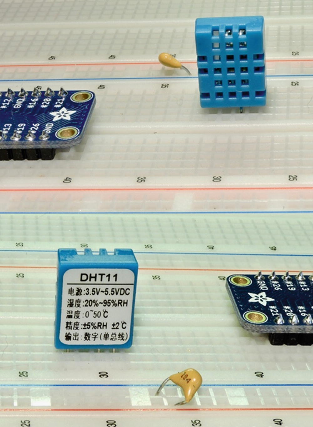
DHT11 sensor front view (left), rear view (right). Pin 1 is the leftmost pin facing the front of the package (left photo).
The DHT11 sensor requires a power supply unlike many 1-Wire peripherals. The datasheet states that the DHT11 can be powered by a range of 3.3 to 5.5 V (this can also be seen on the back of the device in Figure 22-1). Powering it from the Raspberry Pi’s 3.3 V source keeps the signal levels within a safe range for GPIO. The device draws between 0.5 and 2.5 mA. Its standby current is stated as 100 to 150 μA, for those concerned about battery life.
Circuit
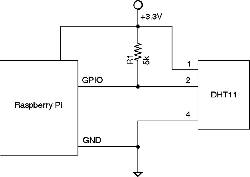
DHT11 circuit
When the Pi is listening on the GPIO pin and the DHT11 is not sending data, the line will float. For this reason, R1 is used to pull the line up to a level of 3.3 V. The datasheet recommends a 5 kΩ resistor for the purpose (a more common 4.7 kohm resistor can be substituted safely). This presents less than 1 mA of load on either the GPIO pin or the sensor when active. The datasheet also states that the 5 kohm resistor should be suitable for cable runs of up to 20 meters.
Protocol
The sensor speaks only when prodded by the master (Raspberry Pi). The master must first make a request on the bus and wait for the sensor to respond. The DHT sensor responds with 40 bits of information, 8 of which are a checksum.
Overall Protocol
- 1.
The line idles high because of the pull-up resistor.
- 2.
The master pulls the line low for at least 18 ms to signal a read request and then releases the bus, allowing the line to return to a high state.
- 3.
After a pause of about 20 to 40 μs, the sensor responds by bringing the line low for 80 μs and then allows the line to return high for a further 80 μs. This signals its intention to return data.
- 4.Forty bits of information are then written out to the bus by the DHT11: each bit starting with a 50 μs low followed by:
- a.
26 to 28 μs of high to indicate a 0-bit
- b.
70 μs of high to indicate a 1-bit
- a.
- 5.
The transmission ends when the sensor drives the line low one more time for 50 μs.
- 6.
The sensor releases the bus, allowing the line to return to a high idle state.
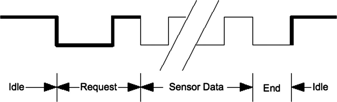
General DHT11 protocol
Data Bits
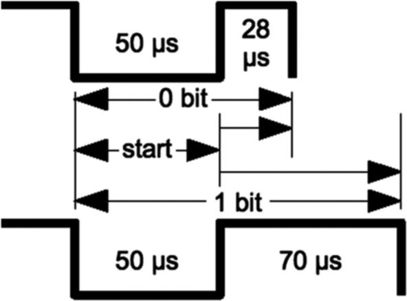
DHT11 data bit
Each data bit starts with a transition to low, lasting for 50 μs. The final transition to low after the last bit also lasts for 50 μs. After the bit’s low-to-high transition, the bit becomes a 0-bit if the high lasts only 26 to 28 μs. A 1-bit stays high for 70 μs instead.
Data Format
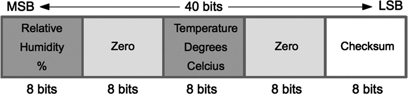
DHT11 data format
The checksum is a simple sum of the first 4 bytes. Any carry overflow is simply discarded. This checksum gives your application greater confidence that it has received correct values in the face of possible reception errors.
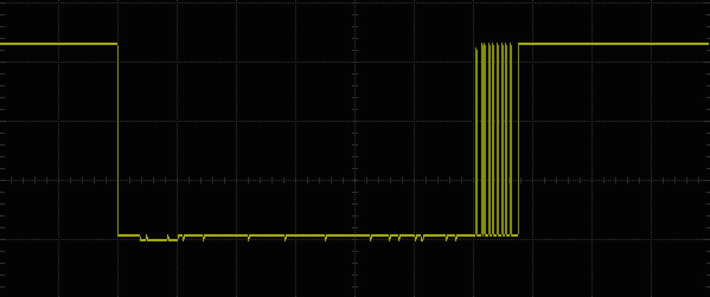
Overview scope trace of the DHT11 signal
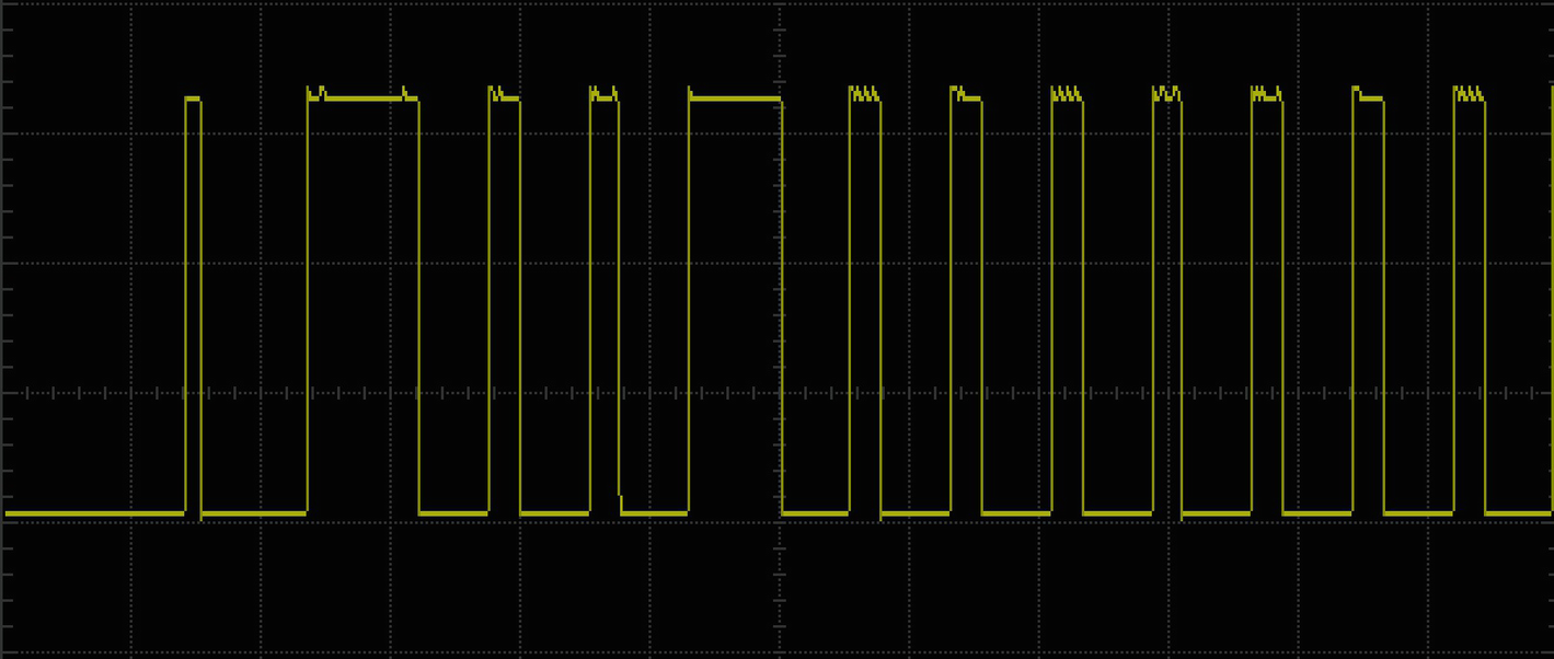
Scope trace of the start of the DHT11 response data bits
Software
Short timings: 26 to 70 μs
Preemptive scheduling delays within the Linux kernel
One approach is to count how many times the program could read the high-level signal before the end of the bit is reached (when the line goes low). Then decide on 0 bits for shorter times and 1s for longer times. After some experimentation, a dividing line could be drawn, where shorter signals mean 0 while the others are 1s.
Source Code
Timing
One of the primary challenges of this application is to perform fast and accurate timings. But we can’t have accurate timing measurements with the NTP daemon (network time protocol) updating the system clock. So rather than rely on the wall clock sense of time, we use the Linux monotonic clock instead. This too can be tweaked by the system slightly, but we are guaranteed that this clock only increments forward in time.
The dht11.c, timeofday() function
- 1.
Capture the initial time (call it t0).
- 2.
Capture the current time after the event (call it t1).
The dht11.c, ns_diff() function to calculate elapsed time in nanoseconds
Main Loop
The top of the main loop in dht11.c
Line 192 initializes the library for direct GPIO access (see source files libgp.c and libgp.h). Following that, the GPIO pin is configured as Output in line 194 and initially driven high in line 195.
The main loop begins in line 197. The counter variable reading is simply used to provide an incrementing reading counter in the output reports. Line 198 initiates the function wait_ready(), which will be described shortly. Its purpose is to prevent the program from querying the DHT11 device more often than once per second. If it is queried too often, the device simply fails to respond.
After it has been determined that the DHT11 device can be queried, line 200 sets the level of the GPIO output to high. Except for the first time into the loop, the GPIO is configured as an input pin. Setting it high before configuring it as an output in line 201 means that there is no glitch when transitioning from its current input state to high when the GPIO becomes an output again. Line 202 simply waits for 3 ms to allow the line to stabilize.
wait_ms( )
The wait_ms() function in dht11.c
wait_ready( )
The wait_ready() function in dht11.c
The static value of variable t0 is established with zeros. When the code is entered for the first time, the date/time is initialized in line 73 and then subtracted by one second (line 74). Subtracting one allows an immediate pass the first time through.
The loop in lines 77 to 84 samples the time every hundred microseconds and returns in line 81 if we have at least one second elapsed, since the last device request.
Reading DHT11
Now comes the fun part—reading the device response. Listing 22-6 illustrates the logic used. Recall that line 206 drives the bus line low, to wake up the device. Then 30 ms is the delay time used before the GPIO is turned into an input pin (lines 207 and 208). By configuring the GPIO as an input pin, we now let the pull-up resistor take over and pull the bus voltage up to +3.3 V.
At this point, the DHT11 will eventually grab the bus and respond. We wait for a line change using the function wait_change() (line 210). It returns the current (final) state of the bus line as well as populating the variable nsec with the nanoseconds elapsed.
Reading the DHT11 response in dht11.c
Upon entry to line 229, the line is low. Waiting for the next transition should report that the bus has gone high, with a time near 80 μs. If the final state is not high, or the time is too long, the response is rejected in lines 230 to 232.
If that passes, the next transition from high to low is measured in lines 240 through 243. Again, if the signal measured is not correct, the response is rejected and the program tries again at the top of the loop.
Finally at line 259, the 40-bit response of the DHT11 is ready to be read.
wait_change( )
The wait_change() function from dht11.c
The program takes a current reading of the GPIO and saves it in variable b0 (line 100). The initial time t0 is captured in line 102. Lines 104 and null statement in line 105 form a tight loop. The current GPIO reading is read and stashed into variable b1. As long as the value of b1 equals the initial value b0, the loop continues. The variable timeout is also tested. As long as the volatile bool timeout remains false, the loop continues. Later on, we’ll see how the timeout value gets set.
The loop normally exits once the GPIO has changed from its initial value. The stop time is captured into t1 in line 106. As long as there is no timeout, line 109 computs and returns the number of nanoseconds elapsed. Line 110 returns the current state of the GPIO.
When a timeout has occurred, we simply return zero for the elapsed time and return zero for the current GPIO value. The purpose at this point is to break out of the while loop. Missed events can occur, especially since the Linux operating system can preempt the execution of the program . If it tries to read 40 bits of data but is missing the reading of one or two signal changes, the loop can be hung forever.
Timout Handling
Given the potential for a program hang, an interval timer is used. At the start of a critical section, the timer is started by calling set_timer(), in Listing 22-8. This starts a timer in the Linux kernel that we don’t have to manage beyond starting.
The interval timer’s configuration is established in the structure timer (line 28 to 31). We don’t want the timer to restart, so the timer.it_interval member is initialized to zero (line 29). Lines 34 and 35 establish the time we want to elapse before the timer expires. Once the timer expires, it will not auto renew.
When the timer expires, the Linux kernel will call our timeout handler named sigalrm_handler() declared in lines 145 to 147. All it does is set the Boolean variable timeout to true. Signal handlers are called as asynchronously. Consequently they must never call non-reentrant routines like printf() or malloc() etc. because the call could arrive at any time. You would not want to call malloc() when the signal interrupted malloc() in the middle of doing its thing.
The timer and handler in dht11.c
The timer setup in dht11.c
Demonstration
On a fast Pi, like the Pi 3 B+, you should see output like this. If you’re not seeing any successful reads, then check your wiring. Don’t forget the pull-up resistor.
Don’t be surprised by this because we are performing real-time measurement of signals on a non-real-time operating system. The Raspberry Pi Zero and Zero W are likely to see more errors due to the lower performance. The Zero will still return good readings often enough to make the project worthwhile. In a finished project, you will simply modify the code to suppress error reports.
Summary
This chapter has tackled the difficulty of reading the DHT11’s real-time signal on a system that does not provide real-time scheduling. Through use of direct GPIO access, we obtained fast enough access to measure signal changes. Applying an interval timer provided recovery safety, if the program got stuck waiting for lost events. These are some of the sneaky things that must be done to solve thorny problems.