
The file s ystem is central to the Unix system design from which Linux borrows. The mass storage requirements have traditionally been fulfilled through hard disk subsystems. However, as hosts become as small as credit cards, flash memory technology has replaced the bulky mechanical drive.
SD Card Media
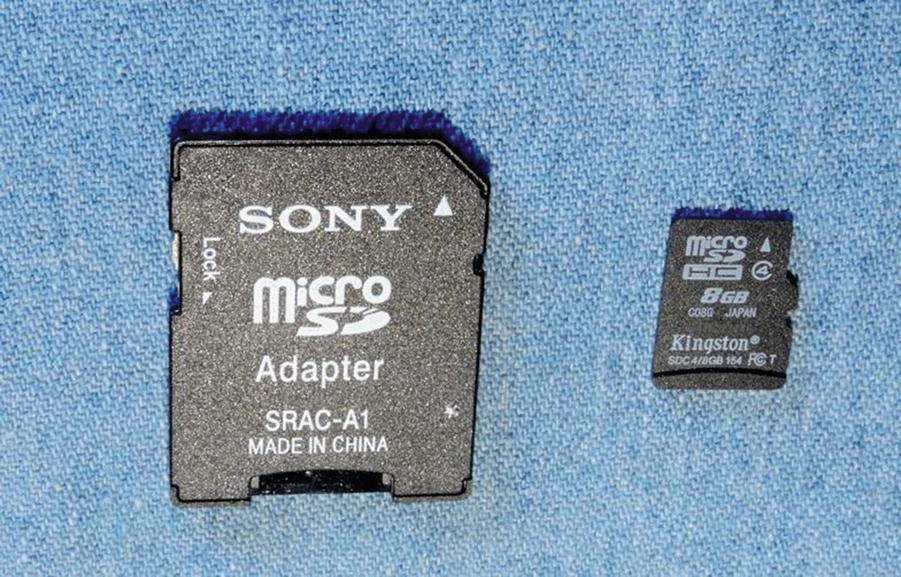
SD MicroSD adapter (left) and 8 GB MicroSD card at right
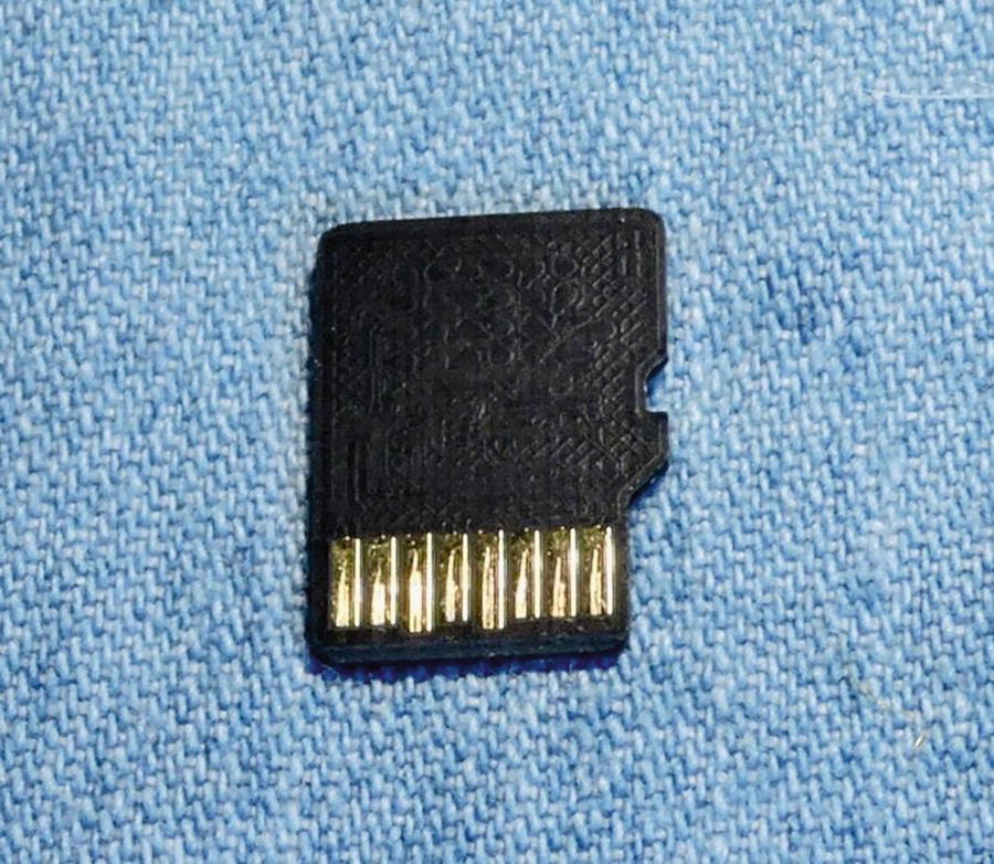
The underside of the MicroSD card, with its 8 pins exposed
SD Card Basics
The SD card includes an internal controller, also known as a Flash Storage Processor (FSP). In this configuration, the host merely provides a command and waits for the response. The FSP takes care of all erase, programming, and read operations necessary to complete the command. In this way, Flash card designs are permitted to increase in complexity as new performance and storage densities are implemented.
The SD card manages data with a sector size of 512 bytes. This was intentionally made the same as the IDE magnetic disk drive for compatibility with existing operating systems. Commands issued by the host include a sector address to allow read/writes of one or more sectors.
Note
Operating systems may use a multiple of the 512-byte sector.
Commands and data are protected by a CRC (cyclic redundancy check) code generated by the FSP. The FSP also automatically performs a read after write to verify that the data was written correctly.9 If the write was defective, the FSP automatically corrects it, replacing the physical sector with another if necessary.
The SD card soft error rate is much lower than a magnetic disk drive. In the rare case when errors are discovered, the last line of defense is a correcting ECC (error correction code), which allows for data recovery. These errors are corrected in the media to prevent future unrecoverable errors. All of this activity is transparent to the host.
Raspbian Block Size
Component | Name | Number | Type |
|---|---|---|---|
Prefix | /dev/mmcblk | MMC block | |
Device number | 0 | 0 | |
Partition number | p2 | 2 |
From the earlier mount command output, notice that the /boot file system was mounted on /dev/mmcblk0p1. This indicates that the /boot file system is from partition 1 of the same SD card device.
The result shown informs us that the Raspbian Linux used in this example uses a block (sector) size of 512 bytes, both physically and logically. This precisely matches the SD card’s sector size.
Disk Cache
The example output displays a b at the beginning of the brw-rw---- field. This tells us that the disk device is a block device as opposed to a character device. (The associated character device would show a c instead.) Block devices are important for file systems because they provide a disk cache capability to vastly improve the file system performance. The output shows that both the root (partition 2) and the /boot (partition 1) file systems are mounted using block devices.
Capacities and Performance
SD Card Capabilities
Standard | Description | Greater Than | Up To | Data Bus |
|---|---|---|---|---|
SDSC | Standard capacity | 0 | 2 GB | 1-bit |
SDHC | High capacity | 2 GB | 32 GB | 4-bit |
SDXC | Extended capacity | 32 GB | 2 TB | 4-bit |
Transfer Modes
SPI Bus mode
1-bit SD mode
4-bit SD mode
SPI Bus Mode
MicroSD SPI Bus Mode
Pin | Name | I/O | Logic | Description | SPI |
|---|---|---|---|---|---|
1 | NC | ||||
2 | /CS | I | PP | Card select (active low) | CS |
3 | DI | I | PP | Data in | MOSI |
4 | VDD | S | S | Power | |
5 | CLK | I | PP | Clock | SCLK |
6 | VSS | S | S | Ground | |
7 | DO | O | PP | Data out | MISO |
8 | Reserved |
Legend for I/O and Logic
Notation | Meaning | Notes |
|---|---|---|
I | Input | Relative to card |
O | Output | |
I/O | Input or output | |
PP | Push/pull logic | |
OD | Open drain | |
S | Power supply | |
NC | Not connected | Or logic high |
SD Mode
Micro SD Mode Pins
Pin | Name | I/O | Logic | Description |
|---|---|---|---|---|
1 | DAT2 | I/O | PP | Data 2 |
2 | CD/DAT3 | I/O | PP | Card Detect/Data 3 |
3 | CMD | I/O | PP/OD | Command/response |
4 | VDD | S | S | Power |
5 | CLK | I | PP | Clock |
6 | VSS | S | S | Ground |
7 | DAT0 | I/O | PP | Data 0 |
8 | DAT1 | I/O | PP | Data 1 |
Wear Leveling
Unfortunately, Flash memory is subject to wear for each write operation performed (as each write requires erasing and programming a block of data). The design of Flash memory requires that a large block of memory be erased and rewritten, even if a single sector has changed value. For this reason, wear leveling is used as a technique to extend the life of the media. Wear leveling extends life by moving data to different physical blocks while retaining the same logical address.
Whether or not a given memory card supports wear leveling is an open question without supporting documentation. Some manufacturers may not implement wear leveling at all or use a lower level of overprovisioning. Wear leveling is not specified in the SD card standard, so no manufacturer is compelled to follow SanDisk’s lead.
Direct File System Mounts
There are times when it is convenient to make changes to a SD card file system with the Pi offline, using Linux. If you have an USB card adapter, this could also be done by a different Pi. Using the SD card slot or a SD card reader attached to your Linux box, you can mount the file systems directly.
lsblk
blkid
Once mounted like this, you can list or change files at will in directories /mnt/1 or /mnt/2.
Read-Only Problem
The switch on the MicroSD adapter has slipped to the “Protect” (or locked) position.
Linux has a software lock on the device.
Or the MicroSD adapter is faulty (bad connection).
MicroSD Adapter Switch
The slide switch for the MicroSD adapter can be a real nuisance as it accidentally gets slid into the “locked” position. The solution is to pull it back out and fix the switch setting.
Software Protection
MicroSD Adapter Quality
When this read-only issue happened to me for the first time, I thought the issue was with the hardware in the Linux computer I was using. Researching this I discovered that some people had reported that their MicroSD adapter was the problem. After trying three different MicroSD adapters, I was eventually successful. The first two adapters failed with a bad connection making the device read-only.
If you got an adapter with your MicroSD card, that is probably the adapter you want to use. However, that may not guarantee success.
Image Files
That dd command copies the input disk (/dev/sdb) to an output file (/tmp/sdcard.img), using a block size of 1 MB (1024k). The large block size is used for greater efficiency.
After unmounting the file systems, you can copy the image file back to your SD card.
Summary
This chapter briefly introduced the SD card and its operation. Then two different ways of working with the SD card file system outside of the Raspberry Pi were examined—mounting the SD card on Linux directly and mounting an image file. Both have their uses, particularly in rescue operations.