
The DS3231 module sold for the Arduino is perfect for the Raspberry Pi because the IC operates from a range of +2.3 to 5.5 V. This permits the Pi user to power it from the Pi’s +3.3 V supply and wire it up to the I2C bus. The module sports a battery backup, allowing it to keep accurate time when the Pi is powered off. The DS3231 includes temperature measurement and adjustment to maintain timekeeping accuracy.
This chapter will exercise the DS3231 with a C program to set and read the date/time. Additionally, there is a 1 Hz output that can be sensed from a GPIO port should you have application for it. The DS3231 RTC (real-time clock) also provides a fairly accurate temperature reading.
DS3231 Overview
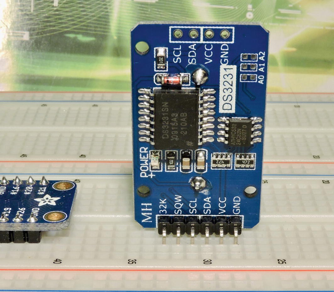
The front view of the DS3231 module inserted into the breadboard
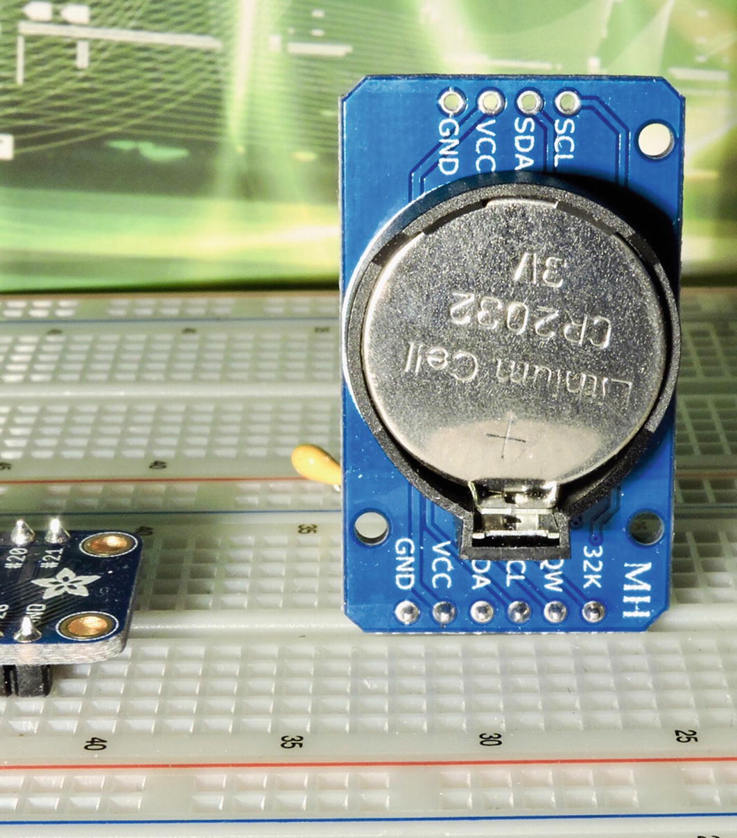
The backside view of the DS3231 with a battery installed
Tip
Buying a fresh battery ahead of time is recommended, since batteries often arrive exhausted or are not included due to shipping regulations.
Hookup

Hookup of the DS3231 to the Raspberry Pi I2C bus
The module runs at +3.3 V so this is easy to wire up because the Pi and the module share the same power source. Simply wire SDA and SCL connections and the power to the device. Don’t forget the ground connection.
The numbers shown are hexadecimal addresses of the discovered devices. The 0x68 device is the DS3231, while 0x57 is the AT24C32 EEPROM device. If your devices fail to be discovered, shut down your Pi and recheck your wiring.
Note
The DS3231 RTC uses I2C address 0x68.
Register Map
The full C language register map for the DS3231
Register 0x00 (Seconds)
For students reading this, an explanation about C language bit fields is in order. The colon and the following number specifiy the bit width of the field. The field being divided up is determined by the type, which in this case is an unsigned byte (uint8_t). The fields listed first specify the least significant bits (on the Pi), while the following bit fields represent higher numbered bits. For example, field s00.secs_1s defines bits 3-0 (rightmost), while s00.secs_10s defines for bits 6-4, and s00.mbz_0 declaring bits 7-6 (leftmost two bits). Specifying bit fields saves us from having to use bitwise and shift operations to move values in and out.
The members secs_1s and secs_10s represent BCD (binary coded decimal) digits, for the time in seconds. So a value of 0x23 (in the uint8_t) byte represents the decimal value 23. These and the other time values are automatically incremented by the RTC (real-time clock) as the DS3231 IC keeps time.
Register 0x01 (Minutes)
Fields with names like mbz_1, are “must be zero” fields and can otherwise be ignored.
Register 0x02 (Hours)
The member values hours_10s and hours_1s are again BCD values representing the hourly time as decimal digits. In the 24-hour format, there is one additional bit to describe the larger hourly 10s digit.
In the 12-hour format, the value of u02.hr12.ampm represents AM when the bit is a 0-bit, otherwise PM.
Register 0x03 (Weekday)
Note that valid values range from 1 for Sunday to 7 for Saturday. Unix/Linux uses the value range of 0–6 for weekday instead.
Register 0x04 (Day of Month)
Members day_10s and day_1s are BCD values for the day of the month with a range of 1 to 31.
Register 0x05 (Month)
The values month_10s and months_1s are the month’s BCD digits with a range of 1 to 12. The member century is provided to indicate a century rollover, from 1999 to 2000.
Register 0x06 (Year)
The year_10s and year_1s member pair provide the BCD digits for the year.
Register 0x07 (Alarm1 Seconds)
Members alrms01 and alrms10 form the pair of seconds digits in BCD form for Alarm 1. Bit field AxM1 is a bit, determines that the seconds must match for the alarm (AxM1=0), or that the alarm is triggered for every second (AxM1=1).
Register 0x08 (Alarm1 Minutes)
The members alrmm10 and alrmm01 specify the BCD pair defining the minutes for the alarm, according to the mask bit AxM2.
Register 0x09 (Alarm 1 Hours)
Like the union u_02 described earlier, there are two views depending upon whether 12 or 24 hour format is used. The hours apply according to the mask bit AxM3.
Register 0x0A (Alarm 1 Date)
This is a union of two views according to whether a weekday (dydt=1) or a day of the month is used (dydt=0). The pair day10s and day1s is the BCD pair specifying the date. The mask AxM4 determines how the date factors into the alarm.
Alarm 2
It otherwise is used the same way.
Register 0x0E (Control)
Member bits A1IE and A2IE enable alarm interrupts when set to a 1-bit. INTCN determines whether the chip emits an interrupt signal (active low) or a square wave output (INTCN=1). Option BBSQW must also be set to a 1-bit to enable the square wave output. Bits RS1 and RS2 when both set to zero choose a 1 Hz rate for the square wave output. CONV is used to enable the reading of the chip temperature. Finally, bit NEOSC (not EOSC) enables the oscillator when a 0-bit and otherwise stops the oscillator when true.
Reading Temperature
- 1.
Check that the BSY flag and CONV flag is not set.
- 2.
Set the CONV flag to begin the conversion.
- 3.
When the CONV flag resets to zero, read the register value at offsets 0x11 and 0x12.
Register 0x0F (Control/Status)
Flags A1F and A2F indicate when the respective alarm has been triggered. The member bsy is the device’s busy flag. Member en32khz enables a 32 kHz signal output, when combined with other options. The oscillator is stopped when flag OSF is set to a 1-bit.
Register 0x10 (Aging)
Register 0x11 and 0x12 (Temperature)
Reading from DS3231
The i2c_rd_rtc() function for the DS3231
This code assumes that the I2C bus has already been opened and the file descriptor saved in i2c_fd (line 137). Two messages are assembled into array iomsgs in line 178. Lines 181 through 184 prepare a write of one byte to indicate that we are addressing starting with register offset 0x00 in the DS3231. Lines 186 to 189 prepare a message to read all of the device’s register into buffer structure rtc. The read is a success when ioctl(2) returns 2, indicating that two messages were carried out successfully.
Writing to DS3231
The function i2c_wr_rtc() for writing to the DS3231
This function is similar to the reading function except that only one ioctl(2) message is required. The RTC values to be written are copied to buf in line 205. The first byte is set to 0x00 to indicate the register number that we want to start writing to. The message is prepared in lines 207 to 210, and the actual write is performed in line 215. The operation is a success when ioctl(2) returns the value 1, indicating one successful message was executed.
Reading Temperature
Reading the DS3231 temperature
The function first loops while the s0F.bsy or s0F.CONV flag is true, indicating that the device is busy. The s0E.CONV flag is set in line 232 and then written out in line 234 to the device. After that, the DS3231 is polled to see when the s0E.CONV flag returns to zero. Once s0E.CONV is reset, we can safely read the temperature from the s11 and s12 registers (line 246).
Demo Time
Read Date/Time
If you get an error, run the i2c-detect again and make sure that the device is wired correctly.
Read Temperature
The accuracy of the temperature reading is fairly decent and this fact is instrumental in its timekeeping stability.
Setting RTC
The second printed line is the value read back from the RTC device. If you need to use a different format for date/time, supply the -f option.
1 Hz Square Wave
From the output, you can see that the input changes at a rate of about one half second (a full cycle requires one second).
Kernel Support
- 1.
sudo -i
- 2.
Edit /boot/config.txt and add line “dtoverlay=i2c-rtc,ds3231” to the file at the end.
- 3.
Uncomment or add “dtparam=i2c_arm=on” to the same file.
- 4.Edit file /lib/udev/hwclock-set and comment out the following three lines, by placing a hash (#) in front:#if [ -e /run/systemd/system ] ; then# exit 0#fi
- 5.
Reboot
This can be confusing when there is a timezone offset involved. In the ds3231 -S command, I set the date/time to the UTC date/time required. Then the command hwclock -s causes it to reset the system sense of time from the DS3231 chip. Following that, the date command reports the local time with my timezone offset.
Summary
The ds3231 is the perfect mate for the Raspberry Pi, particularly when they are not network connected. With its battery backup, the ds3231 will keep accurate time to within a few seconds every month.
The program presented gave you insight into the operation of the chip as well as practice communicating with it from C. Within the C program, a demonstration of the bit fields language feature was applied. This is something often only seen in system or device programming.
Finally, the Raspbian kernel support for the ds3231 was demonstrated so that you can use it in future Pi projects. If you’re looking for an I2C project, why not try communicating with that onboard EEPROM?