Networking has become an important part of everyday life, whether by wire or wireless. Having a network adapter on your Raspberry Pi allows you to connect to it and work from the comfort of your desktop or laptop computer. It also allows your application on the Pi to communicate with the outside world. Even when the Raspberry Pi is deployed as part of an embedded project, the network interface continues to shine. Remote logging and control are just a couple of examples.
Wired Ethernet
The standard Raspbian SD card image provides a wired network connection, using DHCP (dynamic host configuration protocol) to automatically assign an IP address to it. If you are using the HDMI output and keyboard devices to work on the Pi, the dynamically assigned IP address is not a problem. But if you would like to eliminate the attached display and keyboard and operate “headless,” connecting to the Pi over the network is attractive. The only problem is the potentially changing IP address assigned by DHCP.
DHCP will not always use a different IP address because it leases the address for a time. But a dynamically assigned address makes it difficult to connect to your Raspberry Pi from another computer when it changes. As discussed in Chapter 2, you can use the nmap command to scan for it, but this is inconvenient (this example is from Devuan Linux):
root@devuan:~# nmap -sP 192.168.1.1-250
Starting Nmap 6.47 ( http://nmap.org ) at 2018-06-01 19:59 EDT
Nmap scan report for 192.168.1.1
Host is up (0.00026s latency).
MAC Address: C0:FF:D4:95:80:04 (Unknown)
Nmap scan report for 192.168.1.12
Host is up (0.044s latency).
MAC Address: 00:1B:A9:BD:79:12 (Brother Industries)
Nmap scan report for 192.168.1.77
Host is up (0.15s latency).
MAC Address: B8:27:EB:ED:48:B1 (Raspberry Pi Foundation)
Nmap scan report for 192.168.1.121
Host is up (0.00027s latency).
MAC Address: 40:6C:8F:11:8B:AE (Apple)
Nmap scan report for 192.168.1.89
Host is up.
Nmap done: 250 IP addresses (4 hosts up) scanned in 7.54 seconds
root@devuan:~#
If you use your Pi at school or away from home, using DHCP may still be the best option for you. If you are plugging it into different networks as you travel, DHCP sets up your IP address properly and takes care of the name server configuration. However, if you are using your unit at home, or your school can assign you a valid IP address to use, a static IP address simplifies access.
Note
Be sure to get approval and an IP address assigned to prevent network conflicts.
Static Wired Address
The simplest way to set up your static wired ethernet address is to use the graphical desktop and open the dialog for “Wireless & Wired Network Settings.” This is available at the top right of your screen by right-clicking on the WIFI icon, to the left of the speaker icon. Figure 8-1 illustrates.
Figure 8-1
The pop-up menu containing the Wireless and Wired Network Settings dialog
Select and click the selection “Wireless & Wired Network Settings.” A dialog like Figure 8-2 should appear.
Figure 8-2
The Network Preferences dialog box
To configure the wired interface, choose “interface” and then “eth0”. Leave the “Automatically configure empty options” checked if you like, as I did in the figure. Fill in your address, router, and DNS Servers info and click “Apply” and then “Close.” What is updated by this action? The following lines will be appended to the file /etc/dhcpcd.conf:
interface eth0
inform 192.168.1.177
static routers=192.168.1.1
static domain_name_servers=192.168.1.1
With these settings established, the wired ethernet port should automatically be assigned the static IP address 192.168.1.177 in this example.
Wireless Configuration
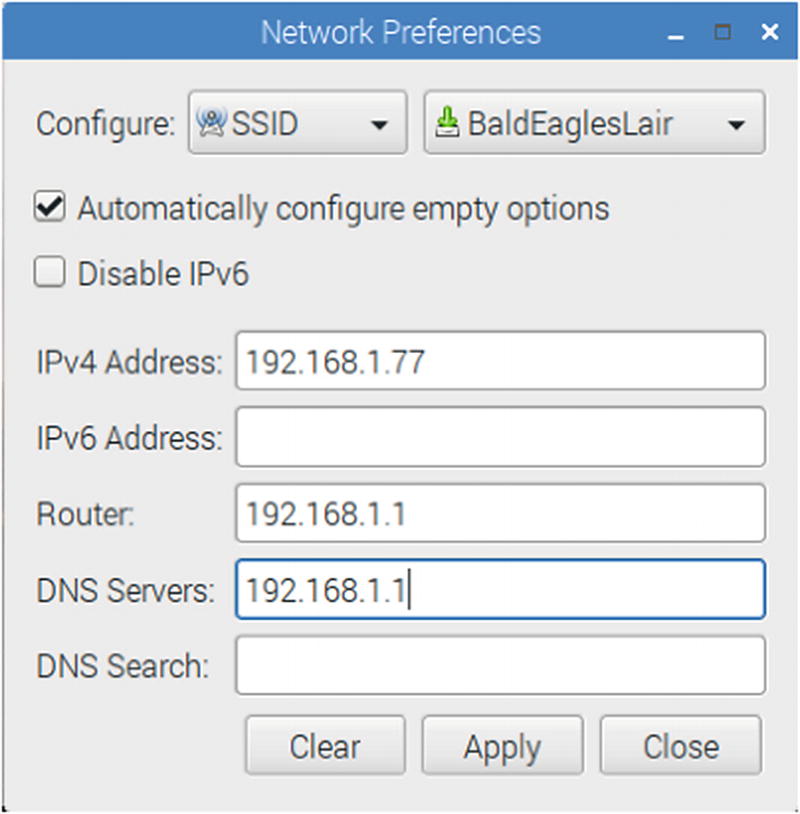
The wireless network interface is configured in a similar way to the wired adapter. Bring up the dialog box that you saw in Figure 8-2, except that you will choose “SSID” instead of “interface.” Figure 8-3 shows the wireless configuration dialog.
Figure 8-3
The Wireless configuration dialog
At the right of “SSID,” choose the wireless network you wish to join. Click Apply and then Close. After you have done this, the file /etc/dhcpcd.conf is updated with:
SSID BaldEaglesLair
inform 192.168.1.77
static routers=192.168.1.1
static domain_name_servers=192.168.1.1
Bugs
The graphical dialog works great except that if you repeat the configuration of the wireless network, you will get added entries at the bottom of the file. If these multiple settings for the same SSID are in conflict, your wireless network may never work. If that is the case, you need to edit the file to remove the conflicting duplicates:
# sudo -i
# nano /etc/dhcpcd.conf
WIFI Country
If you have not already done so, make sure that your WIFI country has been properly configured. From the Raspberry at the top left of the desktop, pull down the menu and select “Preferences” and then “Raspberry Pi Configuration.” Once there click on the “Localisation” tab with an example shown in Figure 8-4.
Figure 8-4
The “Localisation” tab with the WIFI Country setting
Once there, it is a simple matter to click on “Set WIFI Country” to select your country. This is an important configuration item because it determines the legal operating frequencies for your wireless LAN (local area network) adapter in your country.
Test Static IP Addresses
Once you have configured things, the simplest thing to do is to reboot your Raspberry Pi to make the new settings take effect. Usually, the graphical dialogs will make your changes take effect almost immediately.
A good manual check is to use the ifconfig command:
$ ifconfig eth0
eth0: flags=4163<UP,BROADCAST,RUNNING,MULTICAST> mtu 1500
Let’s now check that the names are resolving. Normally, I would recommend nslookup or dig commands for this, but neither comes preinstalled on Raspbian. So let’s just use the ping command:
$ ping -c 1 google.com
PING google.com (172.217.0.238) 56(84) bytes of data.
64 bytes from yyz10s03-in-f14.1e100.net (172.217.0.238): icmp_seq=1 ttl=55 time=17.9 ms
--- google.com ping statistics ---
1 packets transmitted, 1 received, 0% packet loss, time 0ms
rtt min/avg/max/mdev = 17.931/17.931/17.931/0.000 ms
In this example, we see that google.com was looked up and translated to the IP address 172.217.0.238 (your attempt may differ). From this, we conclude that the name service is working. The -c1 option on the ping command line causes only one ping to be performed. Otherwise, ping will keep trying and you may need to ^C to interrupt its execution.
If the name google.com does not resolve, you’ll need to troubleshoot /etc/resolv.conf. It should look something like this (note the nameserver line):
$ cat /etc/resolv.conf
# Generated by resolvconf
search subversive.cats.ca
nameserver 192.168.1.1
For more information about this file, consult:
$ man 5 resolv.conf
USB Adapters
If you have a wired USB ethernet adapter, you can set up networking for that also. An example of a cheap unit is shown in Figure 8-5. It should appear in your dialog as “interface” “eth1” when you have already have a built-in wired adapter like the Raspberry Pi 3 B+. When used for the Raspberry Pi Zero (not Zero W), it will appear as “eth0”. This is a great way to temporarily communicate with your Zero.
Wireless USB adapters can also be used, if your Raspbian Linux supports it. Often device specific firmware needs to be loaded for support. Also keep in mind that the wireless adapter can require from 350 to 500 mA of current from the USB port.
Radicom advertises that their non-wireless model LUHM200 model requires a maximum of 165 mA (unconfirmed if it is supported by Raspbian Linux). A Pi compatibility list is found at this website:
That site lists a few other current consumption figures, including an Apple adapter that requires 250 mA. In general, a wired adapter should consume considerably less than a wireless adapter, and when supported, should require no special driver. My unit shown in Figure 8-5 used about 45 mA.
Figure 8-5
A wired USB ethernet adapter plugged into an USB extension cable
/etc/hosts File
If you have a static IP address for your Raspberry Pi, why not update your Linux, or OS X /etc/hosts file (Windows, typically C:Windowssystem32driversetchosts), with a hostname? For example, your hosts file could have the following line added:
$ cat /etc/hosts
. . .
192.168.1.177 rasp raspi rpi pi # My Raspberry Pi
Now you can use a hostname of rasp, raspi, rpi, or pi to access your Raspberry Pi on the network.
Pi Direct
Given the low cost of Raspberry Pi SBCs (single board computers), you might run another Pi as a satellite off of your main Raspberry Pi 3 B+. If you’re a game developer, you might want to take advantage of the satellite Pi for a VR (virtual reality) display. This offers you 2 x HDMI outputs, if the network connection between the two is fast enough. For lighter graphics loads, you might even use a Raspberry Pi Zero.
To explore this possibility, let’s outline the steps to link two Raspberry Pi’s directly through a wired ethernet connection. I will use a Raspberry Pi 3 B+ accessed through the WIFI (interface wlan0), but link the satellite Pi (Raspberry Pi 3 B, not plus) through the wired eithernet ports on both (interface eth0 on both). The remote (satellite) Pi is to have full access to the internet, via the Pi 3 B+.
It used to be necessary to use an ethernet cross-over cable but now this is unnecessary. The ethernet firmware now auto configures the ports with straight cables. Figure 8-6 illustrates the example network that I will use to make this discussion easier. Take a moment now to soak it in.
Figure 8-6
Example network for Pi 3 B+ and point-to-point connected Pi 3 B
We’re going to focus on the Pi 3 B+ and the Pi 3 B in this example. But note that the internet access for the B+ node arrives over WIFI (interface wlan0), via the WIFI router (192.168.1.1). This is fed through an ISP router at 192.168.0.1. Desktop access to the B+ node is over WIFI as well, using the IP address 192.168.1.77.
The problems to be solved are the following:
Setting up a point-to-point connection between the B+ and the B, using a cable from eth0 to eth0 on both Pi’s.
Enabling IP routing so that all connect requests go through the B+ (from B).
Enable forwarding from the B to the internet (this includes setting up name server access).
Enabling everything except the internet forwarding turns out to be straightforward. Getting the last step to work so that you can upgrade your remote Pi (B) from the internet is a bit tricky. Let’s get started.
Point-to-Point
The first step is to get the Pi 3 B (the remote Pi) to talk to the Pi 3 B+ (B+). This requires cooperation from both Pi hosts. Let’s start from the remote Pi (use the Pi 3 B keyboard, mouse, and display for this initial setup).
Remote Pi Configuration
To get the remote Pi to set up its eth0 wired connection, edit the following file (as root):
# nano /etc/dhcpcd.conf
Add/edit lines so that you end up with:
interface eth0
inform 192.168.2.86
static ip_address=192.168.2.86/24
static domain_name_servers=192.168.1.1
static routers=192.168.2.87
If you’ve been here before, make sure you comment out or otherwise disable old references to the interface eth0.
The inform option tells the DHCP at boot time that ethernet interface eth0 is to be brought up with the IP address 192.168.2.86.
The static ip_address line specifies the same, except that the /24 indicates the boundary between the network and host address.
The static domain_name_servers line configures where name server requests should go. Here we forward name server requests to the WIFI router at 192.168.1.1.
The static routers line is vital here. It directs that all traffic to unknown hosts to be “thrown over the wall” to the Pi 3 B+ host.
192.168.2.87 is the B+ end of that directly connected wired link (review Figure 8-6). It is important that the IP address be the B+ end of that link. If you mistakenly provide 192.168.2.86 instead, it would end up trying to forward to itself (B).
Save those changes and reboot. After it comes up, you should be able to verify its IP address and routing tables as follows (from the keyboard and display):
# ifconfig eth0
eth0: flags=4163<UP,BROADCAST,RUNNING,MULTICAST> mtu 1500
If the link isn’t up (running), don’t worry about that yet. We still have work to do on the B+ end of the connection. Check the routing:
# route -n
Kernel IP routing table
Destination Gateway Genmask Flags Metric Ref Use Iface
0.0.0.0 192.168.2.87 0.0.0.0 UG 202 0 0 eth0
192.168.2.0 0.0.0.0 255.255.255.0 U 202 0 0 eth0
The destination of 0.0.0.0 represents a default destination. We see from the first line that it is configured to be sent to 192.168.2.87 (the B+ end of the point-to-point) link.
The second line indicates that any network requests for 192.168.2.0 will also be routed by the default.
This should complete the remote Pi (B) configuration.
WIFI Pi (B+)
Now we must configure the Pi 3 B+ so that it also brings up the point-to-point interface eth0. Edit its file /etc/dhcpcd.conf so that the following lines remain for eth0:
auto eth0
interface eth0
inform 192.168.2.87
static ip_address=192.168.2.87/24
nogateway
The line auto eth0 brings up the interface when it is available.
The line interface eth0 causes all following lines to apply to this interface.
The inform line tells the DHCP server that interface eth0 will have the IP address 192.168.2.87.
The static ip_address line specifies the IP address and indirectly specifies the netask with the /24.
The nogateway option indicates that there is no gateway to configure (there are no other hosts to be found on the 192.168.2.0 network).
After rebooting your Pi 3 B+ (and Pi 3 B), you should now have a direct link between the two. Check the Pi 3 B+:
# ifconfig eth0
eth0: flags=4163<UP,BROADCAST,RUNNING,MULTICAST> mtu 1500
Hopefully your link has both the address 192.168.2.87 but is also up (“RUNNING”). Check the routine also:
# route -n
Kernel IP routing table
Destination Gateway Genmask Flags Metric Ref Use Iface
0.0.0.0 192.168.1.1 0.0.0.0 UG 303 0 0 wlan0
192.168.1.0 0.0.0.0 255.255.255.0 U 303 0 0 wlan0
192.168.2.0 0.0.0.0 255.255.255.0 U 202 0 0 eth0
From this display, note the following:
The default gateway is 192.168.1.1 (from an earlier WIFI setup). So anything the host doesn’t know how to route will be thrown over the wall to the WIFI router to handle.
Anything that pertains to the WIFI router network (192.168.1.0), also is routed to the WIFI router.
Anything being directed to network 192.168.2.0, is sent to the interface eth0, which is our point-to-point link to the remote Pi.
From this B+ side, let’s test logging into the remote Pi (B), using the remote end’s IP number:
I wish I could tell you that we were done. Unfortunately, there are two more steps remaining. On the B+ we must:
Enable IP forwarding
Configure iptables so it knows how and which packets to forward.
IP forwarding as a feature that is disabled by default because it could lead to a security breach. Having this single setting set to off provides peace of mind when you need it.
Enable IP Forwarding
To turn on IP forwarding, perform:
# sysctl -w net.ipv4.ip_forward=1
net.ipv4.ip_forward = 1
The -w option causes a system file to be updated to save your setting. Without this option, the setting would not be restored upon the next reboot. IP forwarding is not yet in operation yet—this simply gives permission to forward packets.
Configure IP Forwarding
Now we turn our attention to the iptables facility within Linux. If you’re like me, you might be groaning “do I really have to learn all this stuff about firewalls?” Or perhaps “Sigh, I just want it to work!” Bear with me—only a little more is required.
If you’ve not messed with iptables at all, then you can probably skip the clear step. If you already have firewall rules installed that you want to keep, you’ll also want to avoid clearing. Otherwise, let’s check iptables and then clear the rules. First list the filters:
# iptables -L
Chain INPUT (policy ACCEPT)
target prot opt source destination
Chain FORWARD (policy ACCEPT)
target prot opt source destination
Chain OUTPUT (policy ACCEPT)
target prot opt source destination
If all is clear, this is all you should see in the display. When you don’t use the -t option, you are referring implicitly to a table named filters. However, we must also check the table named nat:
# iptables -L -t nat
Chain PREROUTING (policy ACCEPT)
target prot opt source destination
Chain INPUT (policy ACCEPT)
target prot opt source destination
Chain OUTPUT (policy ACCEPT)
target prot opt source destination
Chain POSTROUTING (policy ACCEPT)
target prot opt source destination
The display is empty of any added rules. If you see rules you want to get rid off, use the -F and -X options to clear them all out:
# iptables -F
# iptables -F -t nat
# iptables -X
# iptables -X -t nat
After running these commands, you should be able to get the empty lists as shown before. The -F option deletes all the rule chains. The -X deletes any special user-defined chains. Again, when -t option is absent, it is as if you specified -t filters. The option -t nat applies to the network address translation (NAT) table.
Now we are in a position to tell iptables to forward our packets and apply NAT when necessary.
# iptables -t nat -A POSTROUTING -o wlan0 -j MASQUERADE
This command appends to the nat table to direct any forwarded packet destined to interface wlan0, to be network address translated (NATted). The packets are “masqueraded” to look like they came from 192.18.1.77 (B+), rather than the remote Pi (B).
With this in place, let’s retest on the remote Pi (B).
Second Remote Pi Test
Log into the remote Pi (B) with keyboard, and test the link routing:
$ ping 192.168.1.1
PING 192.168.1.1 (192.168.1.1) 56(84) bytes of data.
64 bytes from 192.168.1.1: icmp_seq=1 ttl=63 time=3.22 ms
64 bytes from 192.168.1.1: icmp_seq=2 ttl=63 time=4.12 ms
^C
--- 192.168.1.1 ping statistics ---
2 packets transmitted, 2 received, 0% packet loss, time 1001ms
rtt min/avg/max/mdev = 3.229/3.675/4.121/0.446 ms
If things are correct, this ping of your WIFI gateway should be successful, as this example shows. So far, so good.
Another good test is to ping google with:
$ ping 8.8.8.8
If this fails, it is probably an indication of problems in the rest of your network (or google).
Assuming that was successful, try testing the name resolver:
# ping google.com
PING google.com (172.217.0.110) 56(84) bytes of data.
...
The fact that it shows you 192.217.0.110 (in this example) an IP number for the name google.com means that the name server is working.
As a final test, you should be able to do an apt-get update:
At this point, you should be able to follow this with the usual:
# apt-get upgrade
Persistent iptables
To avoid having to set up iptables every time, we need to make the rules restorable at boot time. But before we save the rules, let’s make sure we’re not clobbering existing files. The /etc/iptables directory should not exist yet:
# ls -d /etc/iptables
ls: cannot access '/etc/iptables': No such file or directory
If not, then create it now:
# mkdir /etc/iptables
If the directory did exist, check that a file named rules doesn’t already exist or has no important content:
# cat /etc/iptables/rules
Assuming the rules file doesn’t yet exist or has no material content, we can save our iptables rules to this file:
# iptables-save >/etc/iptables/rules
To have iptables rules automatically restored at boot time, create/edit the following file:
# nano /etc/dhcpcd.enter-hook
Add the following line to it:
iptables-restore </etc/iptables/rules
Save the edit. Now when you boot, the DHCP server should perform a restore of your iptables rules, from that file.
Rule Checking
Even when things are going well, it is nice to have verification that this iptables stuff is working. The iptables command can show you what rules are being exercised by listing the rules with counts by the addition of the -v option:
pkts bytes target prot opt in out source destination
From this display we can confirm that 258 packets were forwarded, in addition to the information about INPUT and OUTPUT rules. The same reporting is available for the nat table by adding the -t nat option.
Access
The procedure that was just outlined permits you to log into your remote Pi in an indirect way. Using this chapter’s example, you would first ssh to 192.168.1.77, and from there ssh into 192.168.2.86. Without additional configuration, you would not be able to ssh into 192.168.2.86 directly from the desktop computer. It can be done, but that topic is beyond our scope.
The present arrangement does, however, allow the two Pi’s to communicate directly with each other. Gaming applications can make use of the shared CPU resources and exploit the use of two HDMI displays. As an added bonus, the remote Pi also has the luxury of internet access, which includes the ability to update with apt-get.
Security
This presentation is a get-started example. There are more options and rules that could be applied for greater protection. But if you’re already operating behind a firewall, the added complexity of managing that may not be necessary.
If your Pi is not behind a firewall and you plan to expose your device directly on the internet, then you must take the time to learn more about iptables and firewalling principles.
Summary
This chapter has shown how the wireless and wired ethernet adapters can be configured using the graphical desktop. This is quite suitable for normal and routine cases.
For special configurations, however, things get more involved. The remainder of the chapter covered the editing of files and iptables setup, to build a point-to-point connection. This allows the remote Pi to access the internet through the first Pi. Knowing how to save the iptables configuration and coax the DHCP server to restore those rules at boot time completes the picture. From this starting point, you can expand your knowledge of configuring your network to specialized needs.