

Aircraft Painting and Markings |
5 |
INTRODUCTION
Aircraft are normally painted to provide both protection for the aircraft surfaces and a pleasing appearance. Many different types of finishing materials, generally called paints, are used on aircraft. Each type serves one or more purposes, and each must be applied in some specific manner to ensure proper adhesion and an acceptable durability.
This chapter examines the equipment used to apply paints and the different paints that are commonly used for aircraft. In addition, this chapter discusses the application of paint trim and the application of aircraft registration numbers. Keep in mind that the information in this chapter is general in nature and the manufacturers of specific painting equipment and finishing products should be consulted concerning the proper use and application of their individual products.
Spray painting is the commonly used method of applying paint over large surfaces. The majority of this chapter deals with the spray-painting process.
AIRCRAFT FINISHING MATERIALS
Paint Systems
The paint on an aircraft is referred to as a paint system. A paint system is a family of products that are compatible. A typical paint system includes: cleaners, conversion coatings, primers, and top coats. Most often the individual products in a paint system are not interchangable with other products of a different paint system or a different manufacturer. Modern high-solids paint systems have replaced traditional low-solids paints due to environmental regulations. Figure 5-1 shows a popular paint system used for propeller aircraft.
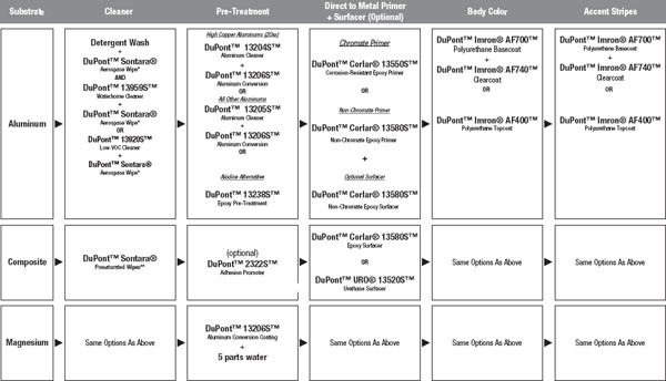
FIGURE 5-1 Recommended paint system of propeller aircraft.
The U.S. Environmental Protection Agency issued new requirements for the use of primers and topcoats with low volatile organic compound (VOC) content effective September 1998. These requirements, called the National Emissions Standards for Hazardous Air Pollutants (NESHAP), reduced the VOC content of primers to 350 g/L from 650 g/L and the VOC content of topcoats to 420 g/L from 600 g/L. The reduction in the amount and type of solvents used in high-solids primer and topcoat created a challenge for both suppliers and users in developing and qualifying acceptable paints. These new paints must meet all engineering performance and application requirements and provide a finished appearance that is acceptable to operators. VOCs are solvents that get released into the air as the paint dries and these solvents could potentially cause harm to the environment. The performance and application requirements of solvents in high-solids paint are divided into two categories: wet film properties and dry film properties. Both these properties have changed for the primer and the topcoat.
Wet Film Properties
Conventional paint (both primer and topcoat) uses large volumes of solvent to keep high-molecular-weight, long-chain hydrocarbon polymers in solution (in a liquid state). This gives the paint a longer application life and makes it easier to apply.
High-solids paint generally contains low-molecular-weight, short-chain polymers to allow for a greater solids density and lower solvent content. As a result, the paint maintains its required flow characteristics while meeting NESHAP requirements for reduced VOC content. The combination of low VOC and high-solids content enables the paint to cross-link more densely. High-solids paint forms many more chemical bonds between resin chains than does conventional paint, making it more stable. Cross-linking affects paint properties such as chemical resistance and flexibility. The flow characteristics of the paint, also called rheology, are controlled with a blend of solvents and additives. The short-chain polymers are viscous liquids that continue to flow after spraying and after all the solvent has evaporated. Controlling the rheology of the paint is critical to producing an acceptable appearance. If the paint viscosity is too low during and after application, the paint will run and sag. Conversely, if the viscosity is too high, the paint does not flow well and the result is a bumpy “orange peel” appearance.
The Eclipse paint system is an example of a high-solids polyurethane topcoat that is used by airframe manufacturers and repair stations to paint transport aircraft. This paint system provides premium gloss and high distinctiveness of image. Figure 5-2 shows the mixing instructions for this paint system.
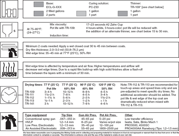
FIGURE 5-2 Mixing instructions for paint system.
It is the responsibility of the technician to understand the nature of the materials and procedures used in applying a paint system to a particular part of an aircraft. The technician should consult the tech sheets and MSDSs prepared by the manufacturer before the application of the paint system.
Paint System Components
Cleaners
Surface preparation for painting of the aluminum skin begins with using an alkaline cleaner or similar product for metal degreasing, removal of paint remover residues, and final cleaning prior to paint. New regulations specified that any cleaning solvents used before painting must have a vapor pressure below 45 mm Hg. More environmental (green) products have been developed to replace traditional fast evaporating cleaners such as 100% MEK with a slower evaporating solvent blend of methyl propyl ketone and MEK and water-based cleaners. Cleaners and degreasers for composite structures could be different from cleaners used for aluminum and the technician must carefully select the correct cleaner to avoid damaging the aircraft.
After the aircraft is cleaned, water is sprayed over the airplane surface to clean it. Premature breaks in the water film are a result of contamination and this indicates that the surface is dirty and further cleaning is necessary. After the surface is free of water breaks, the airplane is ready for pretreatment.
Pretreatment
Aluminum conversion coating is applied to the aluminum skin to prevent corrosion and improve adhesion for the paint system. Alodine is a brand name that is often used for this process. This coating is applied like a wash, allowing the coating to contact the surface and keeping it wet for 2 to 5 min without letting it dry. The chromated conversion coating, alodine 1000, allows the primer to adhere to the oxide that is created on the airplane skin during conversion. Adhesion occurs when the alodine reacts with the aluminum oxide and converts it into a mixed chromate-aluminum oxide, which provides good adhesion for the primer. It then must be thoroughly rinsed with clean water to remove all chemical salts from the surface. Depending on the brand, the conversion coating may color the aluminum a light gold or green, but some brands are colorless. Traditional conversion coatings contain hexavalent chromium which is highly toxic and regulated. New non-hexavalent chromium–based processes are becoming commercially available and new water-based pretreatments are now available that give superior adhesion, improved paint flexibility, and advanced corrosion protection. After the excess alodine is rinsed off and the airplane is dried, it is ready for primer and topcoat.
Wash primers often contain phosphoric acid and are an alternative to conversion coatings and serve as a tie coat over properly prepared uncoated aluminum. The wash primer will reactivate aged or sealed anodized surfaces. Most often wash primers are used to improve the filiform corrosion resistance of an aluminum aircraft and can be used (1) as an alternative pretreatment to chemical conversion coatings, (2) for reactivation of aged anodized or chromated alloys and sealed anodized surfaces, (3) for strip ability of polyurethane systems with alkaline paint removers, and (4) to provide adhesion of subsequent polyurethane or epoxy/ isocyanate primers.
Primers
Primer is applied to adhere to both the aluminum or composite surface (aircraft skin) and the topcoat. The primer protects the aluminum skin from corrosion. Zinc chromate primer, red iron oxide, and gray enamel undercoat primers were used extensively for aircraft painting operations, but due to environmental regulations and the development of newer improved epoxy primers they have largely been replaced by low-VOC high-solids nonchromate epoxy or polyurethane primers. Epoxy and polyurethane primers are two-part materials consisting of a base material and a catalyst. Epoxy and polyurethane primers are compatible with polyurthane topcoats. Most new epoxy primers contain no chromates. A example of this new type of epoxy primer is the DuPont Corlar 13580 non-chromate epoxy primer that is used with DuPont Imron topcoats. Intergard® 10206 is a waterborne two-component chromate-free epoxy primer designed to adhere to multiple substrates (e.g., steel and aluminum). This product has a very low VOC and is easily applied. It is important for the technician to follow the manufacturer’s directions for the product being used in any coating systems.
Topcoats
Topcoats provide the decorative paint scheme for airplanes. Ultraviolet (UV) light degrades certain pigments and resin systems over time. In an acidic environment, such as a volcanic eruption or severe air pollution, color shift occurs (the paint changes color, usually growing darker and less brilliant), and topcoat gloss decreases. Topcoats are available in two types: one-stage and two-stage topcoats. The one-stage topcoat is applied in one operation with all the necessary chemicals in the paint. It often needs to be buffed to produce a high-gloss surface. The two-stage paint system consists of a base coat and a clear coat. The base coat (color) is sprayed over the primer first and the clear coat is applied after the base coat has dried. The two-stage topcoats provide a high-gloss finish and good UV protection.
Primers and topcoats must perform together as a paint system. These systems must be resistant to chemical attack because airplanes are often exposed to hydraulic fluid, fuel, and maintenance chemicals when in service. High-density polymer cross-linking provides the required chemical resistance in high-solids paint, but cross-linking also affects the flexibility of the paint. Flexibility and adhesion of paint systems are crucial because of the thermocycling, aerodynamic forces, and body structure stresses put on the airplane between takeoff and landing.
Content of Paint
Most paint finishes are made up of four basic components: pigment, binder, solvent, and additives.
Pigment provides the color and durability. Pigment gives the paint the ability to hide what is underneath the finish. In addition to providing durability and color, pigment may also improve the strength and adhesion of the paint.
The binder holds the pigment in liquid form, makes it durable, and gives it the ability to stick to the surface. The binder is the backbone of the paint.
Solvent dissolves the binder and carries the pigment and binder through the spray gun to the surface being painted. Most solvents are derived from crude oil. When used with lacquer, this solvent is called a thinner. When used with enamel, it is called a reducer.
Most aircraft finishes also include other components lumped together under the name additives. Additives represent only a small part of the paint, but they can have a significant effect on its physical and chemical properties. Additives are designed to speed drying, prevent blushing, improve chemical resistance, and provide a higher gloss.
Types of Finishes
The exterior of an airplane is painted with one of two basic finishes: acrylic enamels or polyurethane. The majority of all propeller, business, and transport aircraft are painted with polyurethane paint systems. Even many home-built and fabric-covered aircraft use polyurethane paint systems due to superior finish and durability. Lacquers were originally finishes developed in China to produce a high gloss on wood products. However, lacquers are no longer used to paint modern aircraft. Paint systems are specifically developed for different parts of the aircraft such as the exterior of the aircraft; the interior of the aircraft, which has strict regulations regarding smoke emissions during a fire; fuel tanks; wing surfaces; and engine compartments.
Acrylic Enamels
Acrylic enamels were developed in the 1960s and are more durable and have faster drying times than alkyd enamels. Acrylic enamel finishes provide a glossy, hard surface that has good resistance to scratching and abrasion. Their disadvantages include the longer drying time and special precautions that must be taken when repairing any damage to the surface. Various paint manufacturers supply acrylic enamels in both one- and two-part preparations with various characteristics of durability, heat resistance, and weather resistance to match the needs of different aircraft operators.
Polyurethane
Polyurethane finishing materials provide a very high gloss surface with excellent durability, weathering resistance, and abrasion resistance. Due to their resistance to chemical attack, they are often used by aircraft manufacturers in places subject to exposure to strong chemical agents, such as areas containing Skydrol-type hydraulic fluids.
These finishes normally are a two-part mixture, with a catalyst added to activate the drying, or “hardening,” process. Once the catalyst is added, the material has a specific working life, after which it may not be used. These finishes are often part of a finishing “process,” where the finish material provides the best life and durability when used in conjunction with a specific surface-cleaning operation, a surface priming coat, a corrosion inhibitor, and a finish topcoat, as shown in Fig. 5-3.

FIGURE 5-3 Sequence of finishing products for a metal aircraft. (U.S. Paint.)
Polyurethane finishes should not be waxed. Wax tends to yellow the finish, and it collects dirt, reducing the cleanliness of the aircraft surface. Mild soap and water are recommended for cleaning, and solvents are applied with a soft cloth to remove oil and grease.
One problem that is found with polyurethanes is the difficulty in removing them, or “stripping” large areas, with solvents and chemicals. This type of finish resists most stripping materials. Consult the finish manufacturer for specific information about removing old polyurethane coatings.
Thinners and Reducers
Thinners, also called reducers, are used to reduce the viscosity of finishing products so that they will flow properly through the spray gun and onto the surface being painted. Ordinarily thinners are used with enamels and reducers are utilized with lacquers.
A thinner or reducer must be properly balanced to provide proper dilution of the material, so that it will not only pass through the gun smoothly but also atomize easily as it leaves the gun. The paint material must be kept in solution long enough for it to flow out to a smooth, even surface and not allow the paint film to sag or run. The thinner or reducer must evaporate, leaving a tough, smooth, and durable paint finish.
There are two variables that affect the spraying of materials: temperature and humidity. These variables must be carefully observed and compensated for by use of the proper thinner or reducer. Of the two variables, temperature is the most crucial. Hot, dry weather produces the fastest drying time. Cold, wet, or humid weather produces the slowest drying time.
A general rule to follow in selecting the proper thinner or reducer is: the faster the shop drying conditions, the slower drying the thinner or reducer should be. In hot, dry weather, use a slower-drying thinner or reducer. In cold, wet weather, use a fast-drying thinner or reducer.
If a thinner or reducer evaporates too rapidly, the problems that can be caused are orange peel, blushing, and over-spray. If, on the other hand, a thinner or reducer evaporates too slowly, sags and runs may result.
Each finishing product may require a specific reducing liquid. Although some thinners may indicate that they are compatible with all types of finishing products or with a specific group of products, such as all enamels, it is best to only use the reducer recommended by the finish manufacturer. If the wrong thinner is used, the paint may not mix with the thinner, the thinner might prevent the paint from drying, or the thinner may attack the coats of paint beneath the coat being applied.
Epoxy and polyurenthane paint products require a catalyst, also called curing solution, to cure the paint. The catalyst is mixed per instruction with the base material. After mixing there is an induction time of 15 to 20 min before the paint can be applied to the aircraft surface. As soon as the base material is mixed with the catalyst, the curing process starts and these type of products have a limited pot life. The polyurethane paint system in Fig. 5-2 has a 4-h pot life for the color white and a 3-h pot life for colors.
Additives
With the rapid changes made in paint technology during the last decade, the utilization of paint additives has become extremely popular. Additives generally make up no more than 5 percent of the paint at most (and usually much less). Additives perform a variety of vital functions. Some additives can speed up or slow down the drying time. Other additives can raise and lower the finished gloss. Some additives perform a combination of functions, such as eliminating wrinkling, providing faster cure time, and improving chemical resistance.
Those additives that speed up the cure time and improve gloss are often referred to as hardeners. Those that slow drying are called retarders, and those that lower gloss are called flatteners.
Safety
The painting process generally involves the utilization of hazardous materials. It is very important that the guidelines outlined in Chap. 1 on the handling and disposal of these materials be followed. Federal, state, and local codes will dictate the type of safety equipment required for the protection of the operator and others in the area. Protection from hazards such as fire, explosion, burns, and toxic fumes must be provided through the proper utilization of safety equipment, including respirators and eye protection.
All those involved with the finishing of airplanes must keep in mind that many solvents, lacquers, and other materials used are highly flammable. Great care must be taken to ensure that ignition of flammable materials cannot take place.
Dry sanding of cellulose nitrate finishes can create static charges that can ignite nitrate fumes. The interior of a freshly painted wing or fuselage contains vaporized solvents. If a static discharge should take place in this atmosphere, it is most likely that there will be an explosion and fire. It is recommended that wet sanding be performed in every case possible because the water is effective in dissipating static charges.
Finishing materials should be stored in closed metal containers in a fireproof building. The building should be well ventilated to prevent the accumulation of flammable vapors.
The floor of a dope room or paint booth should be kept free of spray dust and sanding residue. These substances can be ignited by static discharges or by a person walking over them. It is recommended that the floors be washed with water frequently to prevent the buildup of flammable residues.
The use of a drill motor to drive a paint-mixing tool should be avoided. Arcing at the motor brushes can ignite flammable fumes.
Solvents and other solutions are often injurious if they splash on the skin or in the eyes. Technicians using these materials should be protected with clothing that covers the body, goggles for the eyes, and an air filter for the nose and mouth.
The use of respirators when spraying finishes is highly recommended, and with some finishing products it is mandatory. Some finishing materials will coat the inside of the lungs and cause health problems. Always check the product manufacturer’s safety recommendations.
A forced-air breathing system must be used when spraying any type of polyurethane or any coating that contains isocyanates. It is also recommended for all spraying and stripping of any type, whether chemical or media blasting. The system provides a constant source of fresh air for breathing, which is pumped into the mask through a hose from an electric turbine pump. Protective clothing, such as Tyvek® coveralls, should be worn that not only protects personnel from the paint but also helps keep dust off the painted surfaces. Rubber gloves must be worn when any stripper, etching solution, conversion coatings, or solvent is used. When solvents are used for cleaning paint equipment and spray guns, the area must be free of any open flame or other heat source. Solvent should not be randomly sprayed into the atmosphere when cleaning the guns. Solvents should not be used to wash or clean paint and other coatings from bare hands and arms. Use protective gloves and clothing during all spraying operations.
SPRAY-PAINT EQUIPMENT
Spray-painting equipment represents a significant investment for any company. If the equipment is properly maintained and used, it will more than pay for itself. If the equipment is misused or not properly maintained, it can cost a lot for a company in terms of damage to aircraft finishes and poor customer relations. Therefore, it is important that all aircraft technicians have a basic understanding of the proper operation, use, and maintenance of aircraft spray equipment.
Spray Booth and Exhaust Systems
It is difficult to produce quality paint finishes without the use of a spray booth. Spray booths are enclosures that provide fire and health protection and are designed to provide a controlled movement of air through the spray area. This allows the incoming air to be filtered and the solvent fumes and overspray to be removed from the spray area. Spray booths come in all sizes and shapes to accommodate the types of spraying being performed. Figures 5-4a and 5-4b show a paint hangar and personnel wearing respirators and protective clothing for the painting of a transport aircraft.
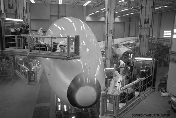
FIGURE 5-4a Paint hangar for transport aircraft. (Airbus.)
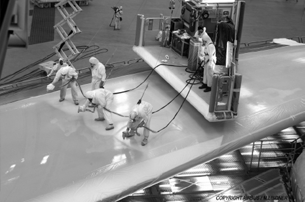
FIGURE 5-4b Wing painting of transport aircraft. (Airbus.)
Compressed-Air Systems
A compressed-air system is an important component of any spray painting operation. A compressed-air system typically includes an air compressor, which produces air that is piped to an air transformer-regulator and fed to the spray gun by a flexible hose. Compressed-air systems collect water that must be drained daily. Both the regulator and compressed-air tank have drain valves for this purpose.
Air Transformer
An air transformer-regulator, shown in Fig. 5-5, is a device that removes oil, dirt, and moisture from compressed air, regulates the air pressure, indicates the regulated air pressure by means of gauges, and provides outlets for spray guns and other air tools.
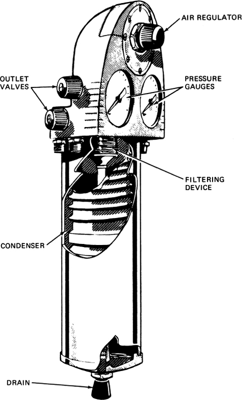
FIGURE 5-5 An air transformer. (DeVilbiss Co.)
The air transformer removes entrained dirt, oil, and moisture by centrifugal force, expansion chambers, impingement plates, and filters, thus allowing only clean, dry air to emerge from the outlets. The air-regulating valve provides positive control, ensuring uniform, regulated pressure. The pressure gauges indicate regulated pressure and, in some cases, main-line air pressure. Valves control air outlets for hose lines to spray guns and other air-operated equipment. The drain valve provides for elimination of accumulated sludge, which consists of oil, dirt, and moisture.
The air transformer should be installed at least 25 ft [8 m] from the compressor and should have its air takeoff from the main line rising from the top of the line. This prevents liquid water from entering the transformer air inlet. The main line should be equipped with a water trap or drains to prevent the accumulation of water. The drain at the bottom of the air transformer should be opened at least once a day to remove moisture and sludge.
Pressure Drop
One of the most important considerations that must be given in the selection and utilization of hoses and fittings is the pressure drop that will occur between the regulator and the spray gun. One of the most important factors in producing a quality paint finish is the ability to maintain the constant desired air pressure. The pressure will always drop whenever a spray gun is turned on and the air begins to flow through the hose. A pressure drop also occurs when air moves through a hose. Pressure drop cannot be eliminated, but it may be reduced through the proper selection and use of hoses. The inside diameter of a hose has the greatest effect on the pressure drop, as illustrated in Fig. 5-6. As the length of the hose increases, the pressure drop will also increase, as shown in Fig. 5-6. The surface smoothness inside an air hose will greatly influence the pressure drop; a rough surface can cause as much as a 50 percent increase in the pressure drop.
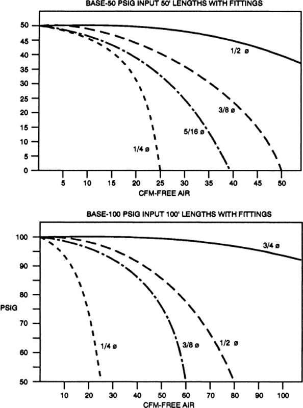
FIGURE 5-6 Pressure drop for various diameter hoses.
Spray Equipment Classification
Spray equipment can be classified into several different types by principles of operation. Different types of equipment may be suitable to specific types of operations. An understanding of the principles of the different types of spray systems will assist the technician in matching the equipment requirements to a specific job.
Airless Spraying
Airless spraying is a method of spray application that does not directly use compressed air to atomize the paint. Hydraulic pressure is used to atomize the fluid by pumping it at relatively high pressure through a small orifice in the spray gun nozzle. The resulting high fluid velocity of the paint flowing through the orifice results in the paint material being atomized. Since air is not being used to atomize the material, the term airless is used to describe this method. Airless spraying is not commonly used on aircraft. Instead, it is better suited to industrial applications where large areas are to be painted and high flow rates are required.
Air Spraying
In air spraying the paint is delivered to the spray gun by either siphon feed, gravity, or pressure feed. Compressed air is introduced at the front end of the spray gun to atomize the paint. The atomizing of the material can take place either outside the air nozzle (external mix) or inside the air nozzle (internal mix).
Environmental regulations have also affected the type of air spraying equipment. Conventional high-pressure spray guns produced a very good finish but the paint transfer to the aircraft skin was relatively low, about 35% of the paint actually transferred to the aircraft and the rest of the paint got lost in the atmosphere. Newer high-volume low-pressure (HVLP) spray equipment has largely replaced older high-pressure paint guns. These HVLP guns can transfer at least 65% of paint upward to 80% due to the lower pressure, which means less overspray and less waste. It is important for technicians to recognize the difference between the two paint gun systems because they look very similar.
Siphon feed is used only on internal-mix spray guns. In the siphon-feed gun, the siphon-type air nozzle sends a hollow column of moving air around the fluid nozzle and, in so doing, draws the paint material out of the paint gun cup, as shown in Fig. 5-7. Siphon-feed spray guns usually operate in the 30- to 60-psi range and 5- to 25-psi range for HVLP guns. Siphon spraying is best suited to smaller paint jobs with the use of light finishing materials that require good atomization. It is ideal for applications where small amounts of color or frequent color changes are required. A gravity-feed gun provides the same high-quality finish as a siphon-feed gun, but the paint supply is located in a cup on top of the gun and supplied by gravity. The operator can make fine adjustments between the atomizing pressure and fluid flow and utilize all material in the cup. Many new paint gun designs utilize the gravity-feed design. Figure 5-8 shows a gravity-feed HVLP gun.
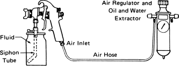
FIGURE 5-7 Siphon spray system. (Binks Manufacturing Co.)
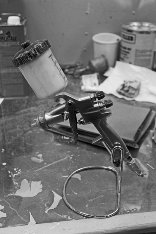
FIGURE 5-8 HVLP gravity paint gun.
In a pressure-feed system, the paint is delivered under air pressure to the spray gun. The pressure container may be either a cup on the gun or a tank, as shown in Fig. 5-9.
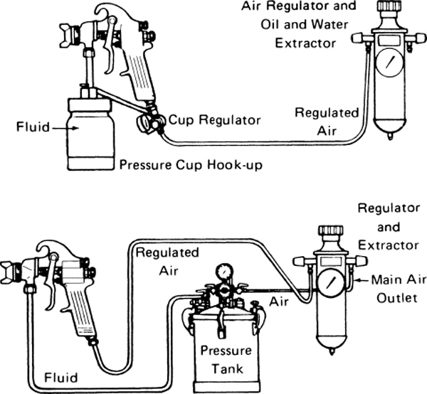
FIGURE 5-9 Pressure spray systems. (Binks Manufacturing Co.)
The pressure tank, also called a pressure pot or pressure-feed tank, is a closed metal container that provides a constant flow of paint or other material to the spray gun at a uniform pressure. These tanks range in size from 2 to 120 gal [7.57 to 454.2 L]. A pressure-feed tank is illustrated in Fig. 5-10.
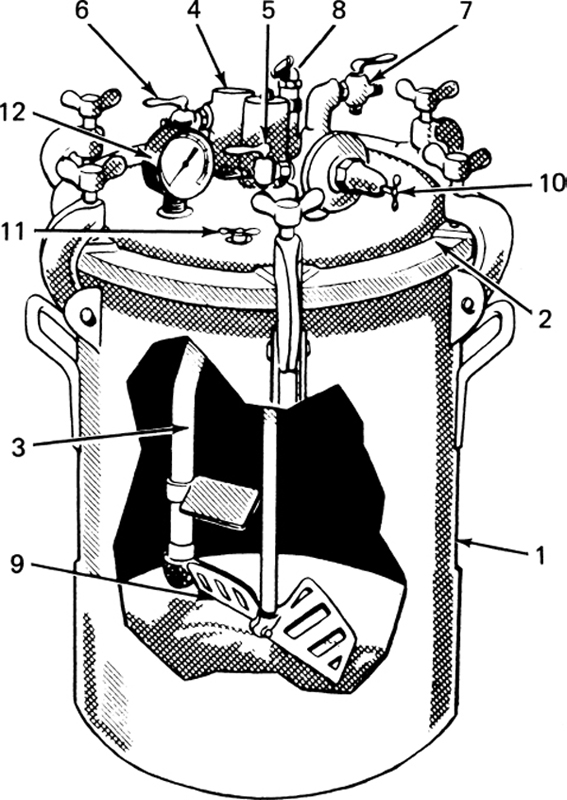
FIGURE 5-10 A pressure tank. (DeVilbiss Co.)
Fluid is forced out of the tank by the compressed air in the tank. To change the rate of fluid flow from the tank, the air pressure is adjusted by means of the pressure regulator. If the tank is the type without a regulator, the air pressure is controlled by an air transformer. Pressure tanks are designed for working pressures up to 110 psi [759 kPa].
As can be seen in Fig. 5-10, a typical pressure feed tank consists of a shell (1), clamp-on lid (2), fluid tube (3), fluid header (4), air-outlet valve (5), fluid-outlet valve (6), air-inlet valve (7), safety relief valve (8), agitator (9), pressure regulator (10), release valve (11), and pressure gauge (12).
The agitator is an essential mechanism for a pressure tank. Its purpose is to ensure that the finishing materials being sprayed are kept in a thoroughly mixed condition. The most convenient type of agitator is driven by an air motor.
Pressure tanks are often utilized with a separate fluid container set inside the tank. This reduces the cleanup problems and makes it possible to change rapidly from one material to another.
The air pressure for which the pressure vessels are rated must not be exceeded, because its failure under pressure could be harmful to operating personnel. The delivery of compressed air supplied to the container is controlled by a pressure regulator. The air-pressure control together with the selection of the fluid-nozzle orifice size and adjustment of the fluid-flow valve provides the rate of flow of the paint from the gun. Pressure-feed painting is well suited to applications requiring medium to large quantities of paint, such as painting an entire aircraft. Many manufacturers and repair stations have switched to HVLP production spray equipment to comply with environmental regulations and to improve the transfer of paint and the reduction of waste.
Electrostatic Attraction
Electrostatic painting may have either air or airless painting systems for atomizing the paint. During the paint-atomization phase, a high-voltage electrostatic charge is placed on the paint particles as they leave the nozzle. This causes the paint particles to be attracted to the nearest grounded object (the item being sprayed), as illustrated in Fig. 5-11. As the paint particles build up on the surface, they exhibit electrical resistance, preventing other particles from attaching themselves to the same place. This action forces the other particles to seek out areas that are still uncoated, resulting in a very uniform coating, which extends into areas that would not normally be coated. Electrostatic spraying generally reduces overspray and results in less paint being used to cover the surface. The limitation associated with electrostatic painting is that the parts being painted must be electrically conductive, and as such it is not generally used on items such as plastic fairings.
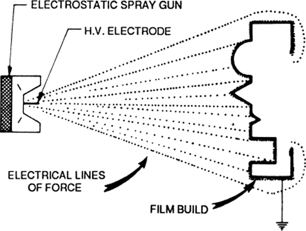
FIGURE 5-11 Electrostatic spray action. (Binks Manufacturing Co.)
Spray Guns
Spray guns are manufactured in a number of different types and sizes. Sizes vary from the small airbrush guns to the heavy-duty production guns used with pressure tanks. Guns are made to spray fluids of various viscosities. Spray guns are manufactured for conventional spraying, HVLP spraying, and airless spraying. The nozzle and air cap of the conventional gun and HVLP gun are designed to mix air with the paint stream to aid in atomization of the liquid. Airstreams are also utilized to shape the pattern deposited by the gun. Airless spray guns do not mix air with the paint before it leaves the nozzle. This results in reduced overspray, less paint “fog” in the air, and a saving of paint. Regardless of the type of spray gun being used, the technician must be certain to adjust it correctly for the type of paint being applied.
One of the popular spray guns for general use in conventional spraying is the type of MBC gun manufactured by the DeVilbiss Company. A gun of this type is shown in Fig. 5-12. Figure 5-13 shows the same spray gun used with a liquid container, also called a cup. The spray gun also can be used with a pressure tank (pressure pot), in which case the liquid is fed under pressure from the tank through a hose to the gun. Spray guns manufactured by the Binks Manufacturing Company are also extensively employed for the application of all types of finishes. The choice, in any case, depends upon the preference of the operator.
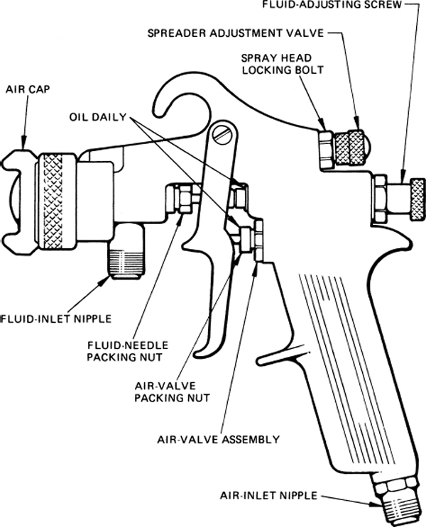
FIGURE 5-12 Drawing of a typical spray gun. (DeVilbiss Co.)
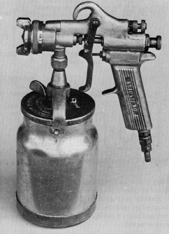
FIGURE 5-13 Spray gun with paint cup. (DeVilbiss Co.)
As shown in Fig. 5-12 a spray gun includes a fluid adjusting screw, which controls the fluid valve, a spreader adjustment valve, an air-valve assembly, an air cap, a fluid inlet, and an air inlet. The balance among air pressure, airflow, fluid pressure, and fluid flow is controlled by adjusting the valves concerned to provide the desired spray quality and pattern. Air flowing through the center area of the air cap and through holes near the center mixes with fluid from the fluid tip and produces an atomized spray. Air flowing from the openings in the horns of the air cap impinges on each side of the fluid spray to produce an elongated spray pattern. This pattern may be adjusted for a wide or narrow area by changing the setting of the spreader adjustment valve. The pattern can be made vertical or horizontal by turning the air cap.
If the spray gun is used with a pressure tank, the fluid is fed under pressure to the fluid inlet of the gun. The fluid pressure must be correct to obtain the proper fluid flow. The pressure is controlled by means of a regulator on the pressure tank.
The air pressure, fluid pressure, airflow, and fluid flow are adjusted to provide the best spray quality for the material being sprayed. Manufacturers often give the most satisfactory settings for the application of each product and also specify the viscosity for best results.
Using a Spray Gun
The difference between a first-class finishing job and a poor job is often determined by the use of the spray gun. An experienced technician who has mastered the techniques in handling a spray gun usually has no difficulty in producing a good finishing job. The first requirement is to have the gun properly adjusted for the type of finishing material being applied.
A good spray pattern depends on the proper mixture of air and paint. Under normal conditions, three basic adjustments will provide a good spray pattern and the desired degree of wetness. First, the size of the spray pattern should be adjusted using the spreader adjustment valve. This valve regulates the flow of air through the holes in the cap. The more the valve is open, the wider the spray pattern. Second, the fluid-adjusting screw should be adjusted to match the fluid volume to the spray-pattern size. Last, it is important to ensure that the air pressure for the gun is correctly adjusted. This pressure is normally controlled by an air transformer. The device acts as a pressure regulator to provide the correct pressure as adjusted by the knob on the top. This unit has fittings for the incoming air from a standard air-pressure line and one or more outlet fittings for the attachment of the air hose to the gun. Many paint guns use a regulator valve and pressure gauge to adjust the pressure at the air inlet of the spray gun (see Fig. 5-8). Conventional paint guns operate at 50 to 60 psi and HVLP paint guns operate at 10 to 25 psi. The tech sheet provided by the paint system manufacturer will prescribe the correct air pressure setting (see Fig. 5-2).
The operator may test the gun by trying it against a test surface. When the desired pattern is obtained, the operator may start applying the finish.
Among the conditions that the operator of a spray gun must observe are the following:
1. The gun must be held at the correct distance from the surface being sprayed (6 to 10 in [15 to 25 cm]). If the gun is held too close, it is likely to cause runs or sagging.
2. Air pressure should be correctly adjusted.
3. The trigger must be released at the end of each pass; otherwise, excessive paint buildup occurs when the direction of spray-gun movement is reversed. This procedure is shown in Fig. 5-14.
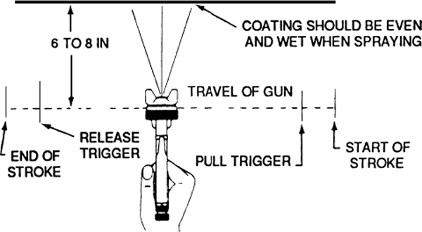
FIGURE 5-14 Correct spray-gun technique. (Binks Co.)
4. The gun must be moved in a straight line, parallel to the surface being sprayed. Moving the gun in an arc causes heavy paint buildup and runs in the center portion of the pass.
5. The gun must be held level and perpendicular to the surface.
6. The correct type of air cap and spray nozzle must be used. Consult the appropriate instructions for the material being sprayed.
7. The paint must be thinned to the correct consistency (viscosity). Manufacturers of aircraft finishes often recommend testing the viscosity with a Zahn viscosity cup. This test is accomplished by placing the required amount of finish in the specified cup and noting the time required in seconds for the finish to drain from the cup.
8. The surface to be sprayed must be clean. A tack cloth may be used to wipe away dust or other particles. A tack cloth is a specially treated soft cloth that removes all dust from a surface but leaves no wax, oil, or other material on the surface that would interfere with the adhesion of coatings.
9. The temperature and humidity must be within the proper range for satisfactory results; otherwise a variety of problems may occur.
The two most common problems in spray painting are tilting the gun and arcing the gun. If the gun is tilted, the part of the spray pattern closest to the surface will receive a heavier film and the part farthest away will get a light covering. If the gun is swung in an arc, the gun will be closer to the surface at the middle of the pass and the paint film will be heavier in that area.
A normal spray pattern for a spray gun forms an elongated oval, with a length 2 to 3 times the width. This is shown in Fig. 5-15(a). This pattern indicates that the spray gun is clean and properly adjusted for the liquid being sprayed. The pattern at (b) is top-heavy and indicates that the horn holes are partially plugged, there is an obstruction on top of the fluid tip, or there is dirt on the air cap seat or fluid-tip seat. Causes for the bottom-heavy pattern at (c) are the same as for the top-heavy pattern, except that the obstruction is on the bottom side of the fluid tip. Heavy right or left patterns, shown in (d) and (e), indicate that one or the other of the horn holes is partially clogged or that there is dirt on either the right or left side of the fluid tip. The heavy center pattern shown in (f) indicates that the spreader adjustment valve is set for too low an airflow, or, for a pressure feed, the fluid pressure is too high for the atomization air being used, or the material flow is in excess of the cap’s normal capacity. The condition can also be caused by too large or too small a nozzle. A split spray pattern (g) is due to air and fluid flows not being properly balanced. Increasing fluid pressure or decreasing spreader air should correct the split spray condition.
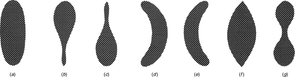
FIGURE 5-15 Correct and distorted spray-gun patterns.
The best results in the use of a spray gun are obtained when the gun is properly maintained and serviced. Bearing surfaces and moving parts should be lubricated daily with a light oil. The lubrication of the gun should be done according to the manufacturer’s instructions.
After each use of the gun, it is necessary that it be cleaned thoroughly to prevent the accumulation of dried paint in the nozzle and paint passages. It is not usually necessary to take the spray gun apart to clean it, because paint solvent sprayed through the gun will ordinarily clean out the paint. The outside of the gun should be thoroughly washed with solvent.
It is desirable to disassemble the gun periodically and inspect it for wear and accumulation of paint and dirt. Worn parts should be replaced.
The packing nuts around the fluid needle and air-valve stem should be kept tight, but not so tight that parts cannot move freely.
It is not wise to allow the gun to become so dirty that soaking of the complete gun becomes necessary. Also, the gun should not be left immersed in solvent or thinner. It is especially important to avoid the use of caustic alkaline solutions for cleaning, because alkalis destroy aluminum alloy components of the gun.
An unbalanced or distorted spray pattern indicates a dirty air cap. The air cap should be removed and washed thoroughly in clean thinner. If reaming of the air-cap holes is necessary, a match stick, broom bristle, or some other soft material should be used. Do not use a hard or sharp instrument, because it may permanently damage the cap.
Spray-gun parts are not ordinarily removed, except for the air cap. When replacing the air-valve assembly, the air-valve spring should be properly seated in the recess in the body of the gun. When removing any parts that seal on a gasket, the condition of the gasket should be examined. When the fluid tip is replaced, it must be tightened carefully.
FINISHING METAL AIRCRAFT AND PARTS
Since all aircraft contain metal parts and most aircraft are of all-metal construction, it is important that the technician be familiar with certain principles involved in metal finishing. In this section, the processes of plating or the special chemical finishes are not discussed because they are not usually in the realm of general airframe maintenance. If such a process is required by the manufacturer, the work can be done by companies that specialize in this type of work.
Paint Removal
For many years, chemical stripping has been the standard procedure for removing paints, primers, and surface contaminants from the surfaces of aircraft components. Although chemical stripping is still frequently used, a new process called dry stripping reduces the environmental hazards associated with the use of chemicals.
Chemical Stripping
Several paint-stripping products are available, and these usually fall into two categories. Wax-free paint remover is a highly volatile liquid that evaporates rapidly after it is applied. For this reason, stripping large areas of an airplane surface with this material is a slow and arduous process. Wax-type stripper has the consistency of thick cream because of the wax, which holds the solvent in contact with the paint surface long enough to lift or dissolve the old coatings. Wax-type stripper is applied with a brush in a thick layer and is allowed to remain on the surface until the coating lifts or dissolves. Some manufacturers recommend laying a polyethylene drop cloth over the stripper-coated surface to slow the drying of the solvents. The stripper should not be removed from the surface until all the paint has lifted or softened. If an area dries before this happens, additional stripper should be applied to the dried area. When all the old finish has softened or lifted, the stripper and finish can be flushed off with water.
Acrylic lacquer will not lift and wrinkle when stripper is applied, but it will soften. When acrylic lacquer has softened, it should be scraped off with a nonmetallic scraper, and then the area should be washed with MEK, acetone, or similar solvent. A powerful spray gun should be used to spray the solvent into cracks, crevasses, and metal joints or seams. The purpose of the solvent is to remove all traces of wax that would otherwise be left by the stripper.
Polyurethane coatings are not easily removed with paint stripper; however, if the stripper is retained on the surface for sufficient time, the bond between the coating and primer is loosened and the coating can be removed. The surface should then be scrubbed with MEK, acetone, toluol (toluene), or xylol.
Paint stripper should not be allowed to come into contact with Plexiglas windows, fiberglass parts, fabric, or other plastic or porous materials. The active agent in the stripper damages some materials and is absorbed by others, neither of which is acceptable.
The principal consideration in the stripping of an airplane is to see that all wax and other residues are completely removed from the surface. This is accomplished by proper solvents, as mentioned, and by washing the aircraft with approved cleaners.
WARNING: Paint-stripping agents must not be used on metal aircraft that employ adhesive-bonded seams rather than riveted seams. Stripping material is likely to penetrate the bonded seams and render the entire structure unairworthy. Manufacturers specify methods by which seams can be masked and protected if stripping operations are necessary.
For specific chemical-stripping procedures, consult the manufacturer of the finish being removed or the stripper’s manufacturer.
Dry Stripping
The dry stripping process utilizes a stream of nonabrasive plastic beads propelled by low-pressure (20 to 60 psi) air to remove materials from the surface that is to be cleaned. The mixture of air and plastic media is accelerated through a venturi nozzle and directed onto the work surface. When the beads strike the surface, paints and contaminants are stripped off.
The unique cleaning capability of this process lies in its ability to control the removal rate of surface buildup without scratching, etching, marring, or otherwise damaging most substrates, thus preserving surface integrity. It also leaves a good surface for painting. Depth of surface removal is controlled by adjusting the distance between the nozzle and the surface, air pressure, and media selection. Thus, only the top layer of paint may be removed, leaving a sound primer or substrate. Chemical stripping does not permit such control.
The individual plastic beads used in the new process have an irregular configuration. They are granular, with sharp, angular edges that provide an extremely effective cutting, shearing, and chipping action to remove paint, carbon, sealants, grease, oil, and dirt deposits. Several different bead sizes are available. The beads can be reused an average of 5 to 10 times, since loss due to wear and breakdown is only 10 to 20 percent per use.
Before the plastic beads were developed, there was no medium on the market that was satisfactory for stripping paint from aluminum and magnesium parts. Hard media such as silica sand or aluminum oxide damaged these metal surfaces. Although a medium made from walnut shells is softer, it disintegrates more quickly. Since plastic beads are a manufactured product, their size, hardness, and consistency can be accurately controlled. The plastic beads are softer than aluminum and magnesium aircraft parts, yet they are sharp and sufficiently hard to remove paint and even chemical-resistant polysulfide primers.
Air pressure is only one variable among many that control speed, safety, and surface finish in the dry stripping process. Other variables that may be controlled are angle of attack, distance from nozzle to workpiece, and hardness and size of the plastic media, and the nozzle size. Optimum nozzle size for airframes is generally in I.D.
There have been a few incidents of airframe damage done by inexperienced operators. The process is operator-sensitive and has its limitations. One type of potential damage is metal expansion due to friction heat buildup or outright pummeling of the delicate metal surface. Keeping a close eye on the surface is essential. Excessive dwell time is a definite factor in this type of damage.
When dry stripping thin plate, it is important to use a low angle of attack and to keep the nozzle moving quickly across the surface, thus allowing heat to dissipate. It is often necessary to go back over an area several times to do a thorough cleaning, but this is generally safer than dwelling on a given area too long. Reducing air pressure—and thus media velocity—is another way to avoid metal expansion.
A related type of damage is unwanted removal of protective coatings such as Al-Clad or anodize. Again, a lower angle of attack, a softer or finer grade of media, and lowered air pressure will prevent this.
For specific dry stripping procedures, consult the directions for the equipment being used. For composite structures, sanding is often the only option because chemical and dry stripping methods could cause loss of fiber material, delamination, or disbonding of a honeycomb sandwich structure. The technician must carefully remove the paint without removing any of the carbon fiber or fiberglass material. A combination of power sanders and hand sanding is required.
Sanding
Sanding is frequently required as a part of the surface preparation or in between the paint finishing coats. Sanding may be performed with either power sanders or by hand. Hand sanding is a simple back and forth scrubbing action with the abrasive paper flat against the surface. On flat surfaces, the abrasive paper should be backed up with a sanding block or pad to produce an even pressure on the sandpaper surface. On flat surfaces a flat, hard sanding block may be used; however, on curved surfaces and on edges, a sponge rubber pad that will follow the contours should be utilized. Two common methods of hand sanding are wet and dry. Dry sanding often results in the paper becoming clogged with the material being removed. In wet sanding, periodically dipping the paper in water will rinse away the removed material. Wet sanding generally produces a smoother finish.
Most heavy sanding is done with power sanders. There are two types of power sanders commonly used in surface finishing, the disc sander and the orbital sander. Both types may be driven by compressed air or electricity.
Corrosion Protection
A metal fuselage is usually painted for two principal reasons: corrosion prevention and appearance. Corrosion is an electrochemical process in which oxygen or other elements combine with metals to form various compounds such as rust, aluminum oxide, metal chlorides, and other metal salts. The first requirement for corrosion is the presence of moisture; the other is a combination of dissimilar metals or metals and chemicals. If a metal is kept dry and clean, it will not corrode; however, a little moisture in the presence of other elements can cause severe corrosion.
In the design and manufacture of aircraft structures, engineers are careful to avoid a design of any assembly of parts that requires the contact of dissimilar metals. If two dissimilar metals must be joined, the surfaces are usually insulated from each other by means of special coatings, treated tapes, or other methods.
When preparing a metal structure for refinishing, the technician must be careful to avoid any condition that can cause corrosion and must remove any corrosion-causing condition that may be found. When in continuous contact with metals, hygroscopic materials (those that absorb and hold moisture), such as leather or canvas, are very likely to cause corrosion. Such materials should be waterproofed before installation.
The improper application of aircraft finishes can lead to filiform corrosion (so named because it forms in fine filaments). If phosphoric acid from an etching solution or wash primer is trapped under subsequent coatings before complete conversion to the phospate film, filiform corrosion will develop under the finish coating, damaging both the metal and the finish. To avoid this condition, it is necessary that there be adequate moisture in the air or in the wash primer to complete the conversion of the phosphoric acid to phosphate. Humidity should be such that a minimum of 0.09 lb of water is present in each pound of air [90 g per kilogram of air]. This is accomplished with a relative humidity of 57 percent at 70°F [21.1°C] or a relative humidity of 49 percent at 75°F [23.9°C]. If the humidity is not great enough to provide the required moisture, a small amount of distilled water may be added to the wash primer. Since a typical wash primer thinner is alcohol, water can be mixed with it.
Another important consideration in the conversion of the phosphoric acid in the wash primer is to allow sufficient time for the conversion to take place before applying the next coating. This is normally 30 to 40 min. If filiform corrosion starts, it will continue until it is removed. If it is discovered, the finish in the affected area and possibly the entire finish of the airplane will have to be removed and all traces of the corrosion eliminated.
Surface Preparation
The preparation of a metal surface for finishing depends upon the type of paint job required. Three general situations are usually considered. The first situation is the painting of a new airplane having a bare, polished Al-Clad finish. The preparation of a new aluminum surface involves only thorough cleaning and treating with a phosphoric acid etch and/ or a wash primer. The phosphoric acid etch is also referred to as a conversion coating.
Another condition involves refinishing an airplane over an old finish. In this case, the technician must determine what type of finish was previously applied to the airplane and then make sure that the material for the new finish is compatible with the old finish. Preparation of an old finish for refinishing usually requires sanding to remove the oxidized outer layer of finish. Any additional treatment required before application of the new finish will be described in the finish manufacturer’s instructions.
The third situation that the technician may encounter is the complete stripping of the old finish and treatment of the metal surface prior to the application of the new finish.
Conversion Coatings
Conversion coatings are applied to fresh, clean metal to aid in preventing corrosion and to microscopically roughen the surface for better adhesion of additional coatings. A conversion coating for aluminum or steel can be a phosphoric acid etch, which leaves a tough, inorganic phosphate film on the metal.
The treatment of a magnesium surface requires a chromic acid etch. This solution can be prepared by mixing approximately l percent chromic anhydride (CrO3), 0.78 percent calcium sulfate (CaSO4), and 98.22 percent water. This solution should be brushed on the bare magnesium and allowed to remain for l to 3 min. It should then be washed off with water and the surface should be dried. After drying, the surface is ready for the application of a wash primer.
Wash Primers
A typical wash primer is described as a two-part butyral-phosphoric acid resin containing corrosion-inhibiting pigments. Other wash primers contain chromic acid as the etching agent. Wash primer may be applied directly to clean, bare metal, or it may be applied over the conversion coating described previously. For best results, it is recommended that the wash primer be applied over the conversion coating.
The wash primer developed by the Stits Aircraft Coatings Company utilizes as many as four types of liquids. These are the pretreatment wash primer and metal conditioner, wash primer reducer, wash primer acid component, and wash primer retarder. To prepare the wash primer for use, the base component of the wash primer is shaken and mixed thoroughly. Then equal parts of the acid and base components are mixed and stirred thoroughly. The reducer is used to thin the mixture, if necessary, to reduce the viscosity, which should be such that the flow from a no. 2 Zahn viscosity cup requires 15 to 18 s. In warm, humid weather, when it is desired to slow the drying time, wash primer retarder is added to the mixture.
Wash primers should be applied in one very thin wash coat, not more than 0.5 mil [0.013 mm] in thickness. The wet, thin coat will penetrate the microscopic craters on the metal surface and any corrosion pits that exist.
Wash primers are manufactured in a variety of formulas by different companies, and it is essential that the technician follow carefully the directions on the container or in the manufacturer’s instruction manual. An important point to observe is the pot life of the primer. After the components of the wash primer are mixed, the pot life is usually from 6 to 8 h. All material should be used during the pot-life period; unused material should be discarded.
Application of Primers
A primer serves two principal purposes: improved bonding and corrosion protection. It provides a bonding layer for the finish coatings in that the primer makes a good with the metal and the finish coating makes a good bond with the primer.
Two-part epoxy primers are popular for use under the urethane and polyurethane coatings. The primer is prepared for use by mixing the required quantity of catalyst with the base component. There is a waiting period (induction time) of 30 to 40 min before the mixture is ready for spraying. This time is necessary to allow the catalytic action to progress to a point where the primer is satisfactory for spraying.
Epoxy primers may be used on steel, aluminum, magnesium, or fiberglass. For the most complete protection against corrosion, the epoxy primer is applied over a wash primer.
Finish coatings should be sprayed over the epoxy primer within 24 h of primer application. Otherwise, the primer forms a hard surface to which the finish coating will not adhere properly. If more than 24 h has elapsed since the application of epoxy primer, the surface can be roughened with 400-grit wet or dry sandpaper, Scotch Brite pads, or other recommended material before the application of finish coats.
Acrylic lacquers and enamels should not be applied over an epoxy primer for at least 5 h (preferably overnight). Acrylics have a tendency to penetrate epoxy primer if it is not fully cured, and this results in a poor surface appearance. Urethane and polyurethane coatings can be sprayed on epoxy primers after 1 h curing time. These coatings soften the surface of the epoxy and form a chemical bond with the primer.
When epoxy primer materials are handled, it is important that the catalyst container be kept tightly closed except when the material is poured. The catalyst is reactive to moisture and will absorb it from the air if the container is not closed. If the catalyst has absorbed considerable moisture and the container is resealed, a chemical action can take place that will cause the container to burst.
Typical instructions for the application of an epoxy primer are as follows:
1. See that the surface is thoroughly cleaned and dust-free.
2. Add exactly one part catalyst to two parts of the primer base component. Stir thoroughly and allow 30 min induction time before application. In high humidity, allow 1-h induction time to avoid curing agent “bloom.”
3. After the two components are mixed, reduce with epoxy reducer to attain a viscosity of 19 to 21 s with a no. 2 Zahn viscosity cup. Additional thinning is required in hot weather.
4. Apply spray coats at 30-min intervals.
Instructions for the application of epoxy primer will vary for different manufacturers. For example, one instruction for a particular product requires a mixture of one-to-one catalyst and base component. This same instruction requires the application of only one coat of primer to a thickness of approximately 0.0005 in [0.013 mm]. It is most important, therefore, that the technician pay strict attention to the appropriate instructions.
Another primer specifically designed for use under urethane coatings is urethane primer. This is a two-part primer, which must be mixed a short time before use and must be used within 6 to 8 h after mixing.
Typical instructions for the application of urethane primer on Al-Clad aluminum are as follows:
1. Mix two parts urethane primer with one part urethane primer catalyst. Add urethane reducer as needed to obtain a viscosity of 18 to 22 s with a no. 2 Zahn viscosity cup.
2. Allow the catalyzed material to stand for an induction period of 30 min.
3. Spray one coat of the urethane primer on the Al-Clad aluminum surface, which has been previously coated with chromate wash primer. Allow to air-dry at 77°F [25°C] for at least 4 h before applying urethane finish coats. Urethane enamel must be applied within 48 h; otherwise the primer will need a light sanding before the enamel is applied.
Three-component polyurethane primers for external use and structural components have been developed that are chromate free and isocyanate cured. These primers are compatible with polyurethane topcoats. These primers consist of a base material, hardener, and thinner. They have a limited pot life and can be recoated in 2 h. Lightly rub the surface with Scotch brite extra-fine pads if more than 72 h expire before the topcoat is applied. Like Epoxy primers there is an induction time of 15 to 30 min after mixing to fully activate the paint system. These produts are typically applied directly over a wash primer.
In some cases, primer or enamel will crater, or crawl, as soon as it is sprayed on the surface. This means that it does not remain flat and smooth but forms small craters and ridges as if being repelled from areas of the surface. This repulsion is usually caused by oil or some other contaminant on the surface. It is usually necessary to remove the fresh coating and thoroughly clean the area with an approved solvent. In some cases, anticrater solutions are available to reduce or eliminate cratering. Such solutions must be used only as directed.
After the application of a primer, the spray equipment should be cleaned thoroughly and immediately. Some primers, such as epoxy primer, will set up hard within a short time and ruin the equipment. Spray guns, paint cups, pressure pots, and paint hoses must be disassembled to the extent possible, and every trace of the primer must be removed. Reducer or MEK is suitable for this purpose.
Topcoat Finishes
A wide variety of finish coatings are available, each with its special characteristics. A number of these finish coatings have been described in this chapter.
Lacquers, both nitrate and acrylic, are quick-drying and easily applied with a spray gun, provided that they are properly thinned with the correct reducer to meet the conditions of temperature and humidity at the time they are applied. Because of their fast-drying characteristics, they quickly dry dust-free. Care must be taken to ensure that lacquers are not sprayed over coatings that they cause to lift and wrinkle.
Enamels do not dry as fast as lacquers and should, therefore, be applied in a dust-free spray booth. Some enamels are designed for air drying, and others should be baked to cure the finish. In any event, the surface of the enamel should be dry before being exposed to conditions where dust may settle and mar the finish.
As mentioned previously, urethane and polyurethane products are being used extensively for finishing aircraft. When properly applied, they provide a high gloss (“wet look”), durability, and ease of maintenance. Typical instructions for a urethane coating are as follows:
1. Prepare the surface to be coated, as previously explained with wash primer and epoxy primer. The primer should have been applied not more than 36 h before the finishing is begun.
2. Mix catalyst in proportions given by the manufacturer. Stir the mixture thoroughly and add reducer to lower to a spray viscosity of 17 to 19 s with a no. 2 Zahn viscosity cup. Filter through a 60 × 48-mesh (or finer) cone filter. Allow a 20-min induction time before spraying.
3. Apply a light, wet tack coat with a spray gun and follow with two medium cross coats at 10- to 20-min intervals. The dry film thickness should be approximately 1.7 mils [0.0017 in, or 0.041 mm]. A DeVilbiss model MBC-S10 or JGA-502 spray gun with a no. 30 air cap and EX tip and needle at 45-lb [310-kPa] pressure has been tested and found satisfactory.
There are varying degrees of thickness for a sprayed top coat. Terms such as dust, mist, single coat, and double coat are commonly used to describe the spray thickness. A very light dry coat is often referred to as a dust coat. An application of slower-drying thinners or reducers over a clear coat is called a mist coat. Double coating is often used in the application of lacquers, where a second spray coating is applied immediately after the first coat is finished. Generally two or more double coats are required to apply a lacquer topcoat properly. Two or three single coats are normally required for enamel topcoats. The first coat should be allowed to become tacky before applying additional coats.
Identification of Finish Coatings
When it becomes necessary to repair or touch up an airplane finish, the nature of the previous coating must be determined in order to ensure that the new coating will adhere to the old coating without lifting or otherwise damaging it.
Various methods and techniques for identification of finishes are employed. To begin, it is a good plan to examine the airplane logbook to see if the finish is identified. If the airplane has not been refinished since new, the type of finish can be identified by the manufacturer.
Cellulose nitrate dope and lacquer dissolve when wiped with a cloth saturated with nitrate thinner or reducer. The distinct odor of cellulose nitrate also aids in making an identification. Synthetic engine oil, MIL-L-7808 or equivalent, softens cellulose nitrate finishes within a few minutes after application but has no effect on epoxy, polyurethane, or acrylic finishes.
MEK wiped onto acrylic finishes picks up pigment but does not affect epoxy or polyurethane finishes unless it is rubbed into the surface.
In all cases where a product is to be used for refinishing, the manufacturer’s instructions should be consulted. Often the instructions provide information regarding the compatibility of other finishes with the finish to be applied.
Touching Up Finishes
Airplane finishes that have become scratched, scraped, cracked, or peeled should be repaired as quickly as possible in order to prevent the onset of corrosion. Any of the old finish that is loose or deteriorated should be removed. It is best to confine the operation to as small an area as possible; however, if the finish is badly deteriorated, it is best to strip an entire panel or refinish the entire airplane.
The old finish can be removed by the careful use of abrasive paper to take off the damaged coating and “feather” in the edges of the damaged area with the original coat. The surface should then be cleaned and all traces of dirt, wax, oil, and other contaminants removed. If the old finish is removed down to bare metal, the same sequence of primers and coatings should be followed as has been previously described. The same type materials as originally used on the aircraft should be used for the repair so that any interaction of products is avoided. If the original type of paint used cannot be located, select a product that will not interact with the coating being repaired.
Spray application of finishes is desirable, and the use of an air brush rather than a large spray gun may be appropriate, depending on the area being repaired. Be sure to protect the surrounding parts of the aircraft and work area from overspray.
Good-quality acrylic finishes are available in aerosol containers, and these may be used for a finish coat, provided that the undercoat material is compatible. Acrylic finish can be applied over epoxy primer if done within about 6 h of the epoxy application. If acrylic lacquer is applied over an old acrylic finish, it is considered good practice to soften the old finish with the application of acrylic thinner, either by wiping or spraying, immediately prior to applying the finish coat. The thinner must be dried before the finish is applied. Urethane enamel can be applied over an old epoxy or urethane coating but should not be applied over an old alkyd enamel surface. The surface should be thoroughly washed with an emulsion cleaner and then steam-cleaned. The surface is then sanded with 280- to 320-grit aluminum oxide or silicon carbide paper and wiped down with MEK or toluol. Urethane enamel can then be sprayed on the surface, as previously explained.
Masking and Decorative Trim
Aircraft are not painted in only one color. Most aircraft contain at least a line or two of decorative trim, with some even being painted in two-tone or multitone color combinations. Even if an aircraft does not have any decorative trim, registration numbers must be applied. The techniques for the application of trim are not complicated, but they do require some care on the part of the painter.
Templates and chalk lines are normally used in laying out the trim lines. The lines should not be laid out with a pencil or pen that can damage the surface or leave permanent marks. The surface of the finish must be hard enough (dry enough) so that this work will not damage the finish. For many finishing materials the paint must not have been on the aircraft more than a few hours or a few days when the trim color is applied. If the paint has been on too long and has cured, the trim color may not properly adhere to the surface coat.
Once the trim lines are laid out, tape is laid along the lines. The tape used should be of a type whose adhesive will not be attacked by the solvents in the trim paint. Propylene fine-line masking tape is a type that is commonly used. This tape also has a smoother edge than conventional crepe paper masking tape and gives a sharp trim line. Paper or plastic is then taped onto the trim tape so that a protective cover is placed over the surface areas next to the trim areas. This protects these surfaces from overspray.
When all the masking and protective covers are in place, the area to be painted is wiped with a clean cloth containing solvent, and after this is dry, the paint is applied.
Rubbing Compounds
Rubbing compounds contain an abrasive such as pumice, which levels the top of the finish, making it smooth. Rubbing compounds are available in various cutting strengths to be used for both hand and machine compounding.
Generally compounds with coarse particles are called rubbing compounds, whereas those with fine particles of pumice are called polishing compounds. Rubbing compounds are used to smooth out the surface being compounded and to remove fine scratches. Polishing compounds are used to smooth the finish and to bring out the gloss of topcoats, particularly with lacquers. Small areas are best done by hand; however, large areas generally are done with air-powered buffers.
Common Painting Problems
If the conditions for the application of an aircraft finish are not correct, one or more irregularities in the paint surface may show up. These irregularities are addressed here as they relate to spray painting.
Runs and sags are usually found on vertical or sloping surfaces and are the result of a heavy coat of paint being applied in an area. The heavy coat has such a buildup that gravity takes over and the paint runs down the surface before it can properly set. This can be caused by an improperly adjusted spray gun, by holding the gun too close, or by moving the gun too slowly.
Starved, or thin film, is the result of the gun being held too far away from the surface and from being moved too rapidly. An improper gun adjustment, providing too little paint or too much air, will also cause this condition.
Dry spray, or texture, is caused by the gun being held too far away, or by too much air pressure.
Blisters, or bubbles, are small raised circular areas with a layer of paint over them. These may be caused by oil or water in the air line of the spray gun. These may also be caused by applying a second coat of paint too soon over a fresh first coat that is still giving off large quantities of thinner.
Blushing means the paint appears to be cloudy or milky. It is caused by the vehicle in the paint evaporating so fast that the surface temperature of the paint is reduced to the point where the moisture in the air condenses and mixes with the paint.
Crazing is when fine splits or small cracks, often called “crow’s-feet,” appear in the finished surface. This is usually caused by the air temperature being too cold.
Fish eyes are small, craterlike openings in the finish. They are caused by improper surface cleaning or preparation. Many waxes and polishes contain silicone, which is the most common cause of fish eyes. Silicones adhere firmly to the paint film and require extra effort for their removal. Additives are available that will help eliminate fish eyes.
Orange peel is the term for paint that creates an irregular surface like the surface of an orange peel. The paint is of varying thickness on the surface and does not flow out properly. It may be caused by improper air pressure at the gun, the gun being held too far away from the surface, or insufficient thinning of the paint.
Peeling is the loss of adhesion between the paint and the surface or the primer coat. This may result from the surface not being properly cleaned and prepared or from the use of an incompatible primer.
Pinholes are small holes or depressions in the paint. These are caused by insufficient drying time between coats of paint or trapped solvents or moisture in the finish.
The correction for each of these problems involves eliminating the stated cause. In some cases, depending on the finishing product being used, the paint may have to be completely removed. In other cases, it may be allowed to dry for some period of time and then sanded lightly before continuing with the process. Still another solution may be to apply a corrective coat to the surface, normally consisting of a combination of paint, thinners, and retarders. In each case, follow the product manufacturer’s recommendations.
REGISTRATION MARKS FOR AIRCRAFT
The finishing of certificated aircraft involves the application of required identification marks as set forth in FAR Part 45. This section gives the general requirements for such markings; however, the technician should consult the latest regulations when applying the markings to an aircraft.
All aircraft registered in the United States must be marked with nationality and registration marks for easy identification. The marks must be painted on the aircraft or otherwise affixed so they are as permanent as the finish. The marks must contrast with the background and be easily legible. The letters and numbers must be made without ornamentation and must not have other markings or insignia adjacent to them that could cause confusion in identification.
Required Markings
The registration and nationality markings for United States—registered aircraft consist of the Roman capital letter N followed by the registration number of the aircraft. The registration number is issued by the FAA when the aircraft is first registered.
When marks that include only the Roman capital letter N and the registration number are displayed on limited, restricted, or experimental aircraft or on aircraft that have provisional certification, the words limited, restricted, experimental, or provisional airworthiness must be displayed near each entrance to the cockpit or cabin. The letters must be not less than 2 in [5.08 cm] or more than 6 in [15.24 cm] in height.
Location of Marks for Fixed-Wing Aircraft
Registration marks for fixed-wing aircraft must be displayed on both sides of the vertical tail surface or on both sides of the fuselage between the trailing edge of the wing and the leading edge of the horizontal stabilizer. If the marks are on the tail of a multivertical-tail aircraft, the marks must be on the outer surfaces of the vertical sections.
If the aircraft has engine pods or components that tend to obscure the sides of the fuselage, the marks can be placed on the pods or other components.
Location of Marks for Non-Fixed-Wing Aircraft
Helicopters or other rotorcraft must have nationality and registration markings displayed on the bottom surface of the fuselage or cabin, with the top of the marks toward the left side of the fuselage and on the side surfaces of the fuselage below the window lines as near the cockpit as possible.
Airships (dirigibles and blimps) must have markings displayed on the upper surface of the right horizontal stabilizer and on the undersurface of the left horizontal stabilizer, with the top of the marks toward the leading edge, and on each side of the bottom half of the vertical stabilizer.
Spherical balloons must display markings in two places diametrically opposite each other and near the maximum horizontal circumference of the balloon.
Nonspherical balloons must have markings displayed on each side of the balloon near the maximum cross section and immediately above either the rigging band or the points of attachment of the basket or cabin-suspension cables.
Sizes of Nationality and Registration Marks
Except for the special cases discussed in FAR Part 45, the height of letters and numbers for fixed-wing aircraft must be equal and at least 12 in [30.48 cm] high.
Marks for airships and balloons must be at least 20 in [50.8 cm] in height. The marks on the bottom of the fuselage or cabin of a rotorcraft must be four-fifths as high as the fuselage is wide or 20 in [50.8 cm] in height, whichever is less. The marks on the sides of the rotorcraft cabin must be a minimum of 2 in [5.08 cm] but need not be more than 6 in [15.24 cm] in height.
The width of the characters in the markings must be two-thirds the height of the characters, except for the number 1 and the letters M and W. The number 1 must have a width one-sixth its height and the letters M and W may be as wide as they are high. The thickness of the strokes or lines in the letters and numbers must be one-sixth the height of the characters. The spaces between the characters must not be less than one-fourth the width of the characters. For 12-in-[30.48-cm] high letters, this equals a width of 8 in [20.32 cm] for all letters except W and M, which are 12 in [30.48 cm] wide, and a 1, which is 2 in [5.08 cm] wide. The space between characters is 2 in [5.08 cm]. Figure 5-16 illustrates the taping and painting of letters and trim on aircraft exterior.
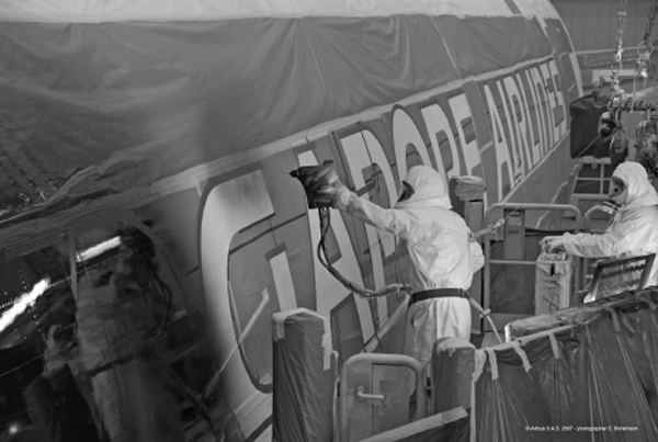
FIGURE 5-16 Taping and painting of letters on aircraft exterior. (Airbus)
Laying Out Letters and Numbers
Letters and numerals for the markings on aircraft are formed as shown in Fig. 5-17. The illustration is not intended to show the correct interval or spacing between the characters but merely to indicate the type and proportions of approved characters.
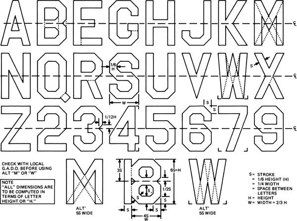
FIGURE 5-17 Letters and numerals for aircraft marking.
To lay out numerals or letters, a master template, such as the one shown in Fig. 5-18, can be constructed. With this device it is possible to lay out any letter or numeral. For some letters or numerals it is necessary to do a small amount of additional construction, but the template will provide the principal guidelines. Some people find that an additional template measuring 2 × 12 in [5.08 × 30.48 cm] aids in making the diagonal lines of the characters. This guide can be made of Plexiglas or sheet metal.
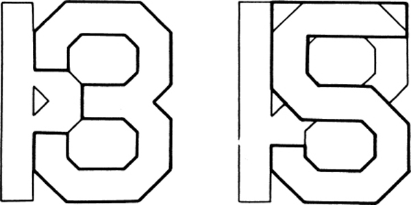
FIGURE 5-18 Template for laying out letters and numerals.
When laying out the registration letters and numbers on the side of the aircraft, light guidelines are drawn with chalk, and after the letters are outlined properly, paint trim tape is laid along the lines and masking, and covers are placed over the rest of the aircraft to protect it from over-spray. The masked-off characters are wiped with a soft cloth containing solvent to remove chalk marks and any oil or other contaminants. The surface is then sprayed with the appropriate color.
Stencils for laying out registration numbers are available, as are decals. The stencils are faster than laying out the number by hand, but additional expense is involved. The use of decals may be warranted if spraying is not practical or if the numbers are only temporary.
REVIEW QUESTIONS
1. Describe the primary functions of a primer.
2. Describe a wash primer.
3. Why is an epoxy-type primer supplied in two parts?
4. What basic components make up paint?
5. What are the two types of exterior paint commonly used on aircraft?
6. What are the advantages of polyurethane enamel?
7. What is the function of thinners and reducers?
8. What is the purpose of using additives in the paint?
9. Why are respirators used in conjunction with paint spraying?
10. What are the functions of an air transformer?
11. How often should an air transformer be drained?
12. How do air-hose diameter and length affect pressure drop?
13. List two common types of air-spraying equipment.
14. Describe a paint pressure tank.
15. What is the advantage of electrostatic painting?
16. Describe the operation of a spray gun.
17. What are the adjustments on a spray gun?
18. How is the shape of the spray pattern adjusted?
19. What will happen if the spray gun is moved in an arc when spraying instead of parallel to the surface?
20. List two methods of stripping paint from an aircraft.
21. What precautions must be observed when chemical-stripping an aircraft?
22. What variables may be controlled when dry-stripping an aircraft?
23. Why is it necessary to avoid contact between dissimilar metals in an aircraft structure?
24. What condition can lead to filiform corrosion?
25. What may be done to slow drying time if relative humidity is comparatively high when wash primers are applied?
26. What is the purpose of a conversion coating?
27. What is the value of an etch for a metal surface before finishing?
28. What are the principal reasons for applying a primer before finishing a metal surface?
29. What precautions must be taken in the application of a lacquer finish over other finishes?
30. What causes runs or sags to appear when using a spray gun?
31. What devices may be used to assist in the laying out of aircraft markings?
32. What type of tape should be used when laying out aircraft paint trim lines?
33. What markings are required on any aircraft registered in the United States?
34. Describe the form and size of the characters used for official aircraft markings.
35. What is the total length of the area on which the N-number N1234M is installed if 12-in [30.48-cm] letters are used?
..................Content has been hidden....................
You can't read the all page of ebook, please click here login for view all page.