

Welding Equipment and Techniques |
6 |
INTRODUCTION
The technician may be called upon to repair important aircraft parts by welding. If the technician does not understand the process of welding or is careless, the weld may fail. It is, therefore, essential to be well acquainted with the approved welded repairs, techniques for welding, and the operation of welding equipment. The technician who is not sufficiently skilled to perform an airworthy welded repair should call upon a qualified welder to do the work. In any event, the technician must be able to inspect and evaluate the quality of any welded structure or welded repair.
FUNDAMENTALS OF WELDING
Types of Welding
Welding is a process used for joining metal parts by either fusion or forging. Forge welding is the process used by a blacksmith when heating the ends of wrought iron or steel parts in a forge fire until the ends are in a plastic state and then uniting them by the application of mechanical pressure. Even today this mechanical pressure is sometimes the result of blows from a heavy hammer. Fusion welding is the process used by welders in the aviation industry and other industries in which enough heat is applied to melt the edges or surfaces of the metal so that the molten (melted) parts flow together, leaving a single, solid piece of metal when cool. In both forge and fusion welding, the process is described as a thermal metal-joining process because heat is required. Only fusion-type welding is used in aircraft work.
Typically, the types of fusion welding used by the technician are oxyacetylene (or oxyfuel) welding, commonly called gas welding,electric-arc welding, and inert-gas arc welding. A variety of special welding processes and techniques have been developed, but these are generally employed only in the original manufacturing processes.
Gas welding and inert-gas arc welding are the most frequently used of all welding processes in aviation. Gas welding produces heat by burning a properly balanced mixture of oxygen and acetylene or other fuel as the mixture flows from the tip of a welding torch. Since the temperature of an oxyacetylene flame at the tip point of the torch may be 5700°F [3149°C] to 6000°F [3316°C], it is apparent that it is hot enough to melt any of the common metals.
Another gaseous fuel that produces almost as much heat as acetylene is a mixture of methylacetylene and propadiene stabilized. Sold under the name of MAPP® by Airco Welding Products, this fuel is safer than acetylene because it does not become unstable at any operating pressure.
The heat required for the fusion of metal parts can be produced by an electric current. Electric welding includes electric-arc welding, electric-resistance welding, and inert-gas-arc welding. In electric-arc welding, the heat of an electric arc is used to produce fusion of the parts by melting the edges of the parts being joined and the end of the welding electrode and then allowing the molten metal to solidify in a welded joint. The arc is formed by bringing together two conductors of electricity, the edges being joined and the electrode, and then separating them slightly. Electric-resistance welding is a process whereby a low-voltage, high-amperage current is brought to the work through a heavy copper conductor offering very little resistance to its flow. The parts are placed in the path of the current flow, where they set up a great resistance to it. The heat generated by the current flow through this resistance is enough to fuse the parts at their point of contact. Spot welding and seam welding are common versions of electric-resistance welding.
Inert-gas-arc welding is a process in which an inert gas such as helium or argon blankets the weld area to prevent oxidation of the heated metal. This is particularly important in welding titanium, magnesium, stainless steels, and other metals that are easily oxidized when subjected to melting temperatures. Tungsten inert-gas (TIG) welding and metal inert-gas (MIG) welding are commonly used forms of inert-gas welding. The names Heliarc® and Heliweld® are trade names that have been used to designate tungsten inert-gas welding when helium is used as the inert gas.
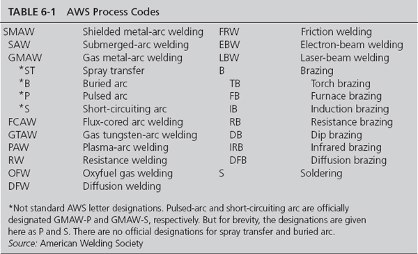
The American Welding Society (AWS) has developed a series of codes used to standardize the identification of the various processes. The AWS process codes for welding techniques are identified in Table 6-1.
Identification of Metals
The technician must be able to identify various metals before attempting to weld them so that the proper torch tip, filler rod, and technique required can be determined. In some organizations, metals may be marked with painted bands of different colors on tubes and bars or by means of numbers on sheet stock. When acquiring the material from stock, the technician should be sure that the material not used retains the material identification coding or is recoded in the same manner as the original material.
Where there are no colored bands or numbers on the metal, three types of tests are commonly used: (1) spark test, (2) chemical test, and (3) flame test.
In the identification of metals by means of the spark test, ferrous metals may be recognized by the characteristics of the spark stream generated by grinding the material with a high-speed grinding wheel. A ferrous metal is one that contains a high percentage of iron. In general, nonferrous metals cannot be identified by a spark test because they do not produce a large shower of sparks and, in fact, may produce almost none.
In applying the spark test the technician should obtain samples of various metals in order to compare the pattern of a known material with the pattern produced by the material being identified. When a known sample produces the same spark characteristics as the unknown piece of metal, identification is accomplished. The characteristics to be observed are: (1) the volume of the spark stream, (2) the relative length of the spark stream (in inches), (3) the color of the spark stream close to the grinding wheel, (4) the color of the spark streaks near the end of the stream, (5) the quantity of the sparks, and (6) the nature of the sparks.
In volume, the stream is described as extremely small, very small, moderate, moderately large, and large. The relative length may vary from 2 to 70 in [5 to 177 cm], depending upon the metal. For example, cemented tungsten carbide produces an extremely small volume of sparks and the stream is usually only about 2 in [5.08 cm] long. On the other hand, machine steel produces a large volume and may be about 70 in [180 cm] long. These particular figures apply when a 12-in [30.48-cm] wheel is used on a bench stand. The actual length in each case depends upon the size and nature of the grinding wheel, the pressure applied, and other factors.
In color, the stream of sparks may be described as red, white, orange, light orange, or straw-colored. The quantity of sparks may be described as none, extremely few, very few, few, moderate, many, or very many. The nature of the sparks may be described as forked or fine and repeating (exploding sparks). In some cases, the sparks are described as curved, wavy, or blue-white, but in most instances the terms previously given apply.
Some handbooks for welders include tables showing these characteristics of the sparks, but all the terms used to describe the spark stream are only comparative. One person may describe a color as orange, whereas another person will refer to the same stream of sparks as light orange or even straw-colored. Because of this situation, the use of the known samples saves time and improves accuracy.
The chemical test for distinguishing between chrome-nickel corrosion-resisting steel (18-8 alloy) and nickel-chromium-iron alloy (Inconel) should be known by welders. A solution consisting of 10 g cupric chloride dissolved in 100 cm3 hydrochloric acid is used. One drop is applied to the unknown metal sample and allowed to remain on the metal for about 2 min. At the end of this time, three or four drops of water are slowly added with a medicine dropper. The sample is then washed and dried. If the metal is stainless steel, the copper in the cupric chloride solution will be deposited on the metal, leaving a copper-colored spot. If the sample is Inconel, the spot left will be white.
A flame test is used to identify magnesium alloys. The welding flame is directed on a small sample until the metal is brought to the melting point. If the metal sample is magnesium alloy, it will ignite at once and burn with a bright glow.
Types of Weld Joints
A joint is that portion of a structure where separate base-metal parts are united by welding. The word weld is often used to refer to a joint. For example, a butt weld is a welded butt joint. The word seam is often used to refer to a welded joint, especially in a case of tanks and containers. Five different types of joints, illustrated in Fig. 6-1, are used to weld the various forms of metal. These are (1) butt joints, (2) tee joints, (3) lap joints, (4) corner joints, and (5) edge joints. In addition to the various types of joints, the technician should be aware that the edges of the materials to be welded may require special preparation. The type of edge preparation required depends upon the materials being welded and the techniques used in the welding process. Where appropriate, edge preparation will be discussed as a part of the description of the various welding processes.

FIGURE 6-1 Types of welding joints.
Butt Joints
A butt joint is a joint made by placing two pieces of material edge to edge in the same plane so that there is no overlapping. It is called a butt joint because the two edges, when joined, are abutted together. There are two classifications of butt joints: plain butt joint and flange butt joint. The plain butt joint is used where the two pieces of the materials to be welded are aligned in approximately the same plane. Flange butt joints are welded using edges that are turned up 90°, producing a flange height of from one to three times the thickness of the material being welded. The flanges are fused together during the welding process. Since the flanges supply enough metal to fill the seam, a filler rod is not normally used. The result is a joint that appears similar to that of a plain butt joint.
Tee Joints
A tee joint is a form of joint made by placing the edge of one base part on the surface of the other base part so that the surface of the second part extends on either side of the joint in the form of a T. Filler rod is used with tee joints.
A plain tee joint is acceptable for most metal thicknesses in aircraft work and also may be used for heavier metals, where the weld can be located so that the load stresses will be transverse (perpendicular) to the longitudinal dimensions of the weld. The only preparation required is cleaning the surface of the horizontal member and the end of the vertical member. The weld is then made from each side with penetration into the intersection. This results in a fillet weld, having a general triangular cross-sectional shape. (Any weld that joins two parts that are at right angles to each other may be called a fillet weld. Corner joints, lap joints, and edge joints also require fillet welds.)
Lap Joints
A lap joint is a joint made by lapping one base over the other and is used in plate, bar, tubing, and pipe. These joints are widely used in the construction of articles fabricated from plate and sheet metal (flat, wrought metals), but a lap joint is not as efficient as a butt joint for distributing load stresses. A lap joint is commonly used where the primary load stress will be transverse (perpendicular) to the line of weld.
A single-welded lap joint is used for sheet, plate, and structural shapes where the loading is not severe. The same type of joint can be used for telescope splices in steel tubing, and in that application it is better than a butt joint.
A double-welded lap joint is used for sheet and plate where the strength required is greater than that which can be obtained when a single weld is used. This type of joint provides for great strength, when properly made, in all ordinary thicknesses of sheet and plate.
The offset, or joggled, lap joint is used for sheet and plate where it is necessary to have a lap joint with one side of both plates or sheets in the same plane; that is, on one side the surface is flush. This type of joint provides for a more even distribution of load stresses than either the single or double lap joint, but it is more difficult to prepare.
Edge Joints
An edge joint is a form of joint made by placing a surface of one base part on a surface of the other base part in such a manner that the weld will be on the outer surface planes of both parts joined. This type of joint is not used where a high joint strength is required, but it is widely used for fittings composed of two or more pieces of sheet stock where the edges must be fastened together. This use is acceptable because the joint is not subjected to high stresses. Edge joints can be used also for tanks that are not subjected to high pressures.
Edge joints are usually made by bending the edges of one or both parts upward at a 90° angle, placing the two bent ends parallel to each other, or placing one bent end parallel to the upright unbent end and then welding along the outside of the seam formed by the two joined edges.
Corner Joints
A corner joint is made by placing the edge of one part at an angle on an edge or a surface of another part so that neither part extends beyond the outer surface of the other, the structure resembling the corner of a rectangle.
There are three types of corner joints for plate and sheet. The closed type of corner joint is used on lighter-gauge metals, where the joint is subjected only to moderate stresses. It is made without adding much, if any, filler rod because the edge of the overlapping sheet is melted and fused to form the bead.
The open type of corner joint is used on heavier sheet for the same purpose as a closed type of corner joint. It is made by fusing the two edges at the inside corner and adding enough welding rod to give a well-rounded bead of weld metal on the outside.
In the third case, if such an open joint is required to bear a fairly heavy load, an additional weld must be made on the inside corner to provide the necessary strength where a light concave bead has been laid on the inside.
Welding Characteristics and Nomenclature
To make a proper weld it is necessary to identify the characteristics of a correct weld. The technician should also be aware of the changes in material characteristics that may take place as a result of the welding operation.
Parts of a Weld
Figure 6-2 shows the names of the parts of a weld. The face is the exposed surface of the weld. The root is the zone at the bottom, or base, of the weld; in other words, it is the depth that fusion penetrates into the base metal at the joint. The throat is the distance through the center of the weld from the root to the face. The toe is the edge formed where the face of the weld meets the base metal; that is, it is the edge of the fusion zone in the base metal on each side of the weld. The reinforcement is the quantity of weld metal added above the surface of the base metal (the metal in the parts being joined) to give the weld a greater thickness in cross section. Materials welded by the electric-resistance process may not have a reinforcement, depending upon the details of the technique used.
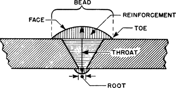
FIGURE 6-2 Nomenclature of a weld.
Other terms not illustrated in Fig. 6-2 are as follows: (1) The leg is the dimension of the weld metal extending on each side of the root of the joint, and (2) the fusion zone is the width of the weld metal, including the depth of fusion in the base metal on each side of the joint.
In Fig. 6-2, the bead is shown. This is the metal deposited as the weld is made. In order to have good penetration, the base metal at the joint must be melted throughout its thickness; hence a bead of weld metal should be visible on the underside of a butt joint, as shown in Fig. 6-2. A good indication of penetration in the case of a fillet weld is the presence of scale on the lower side.
Figure 6-3 consists of three drawings that illustrate the meaning of width of fusion, reinforcement, throat, root, leg, and toe.
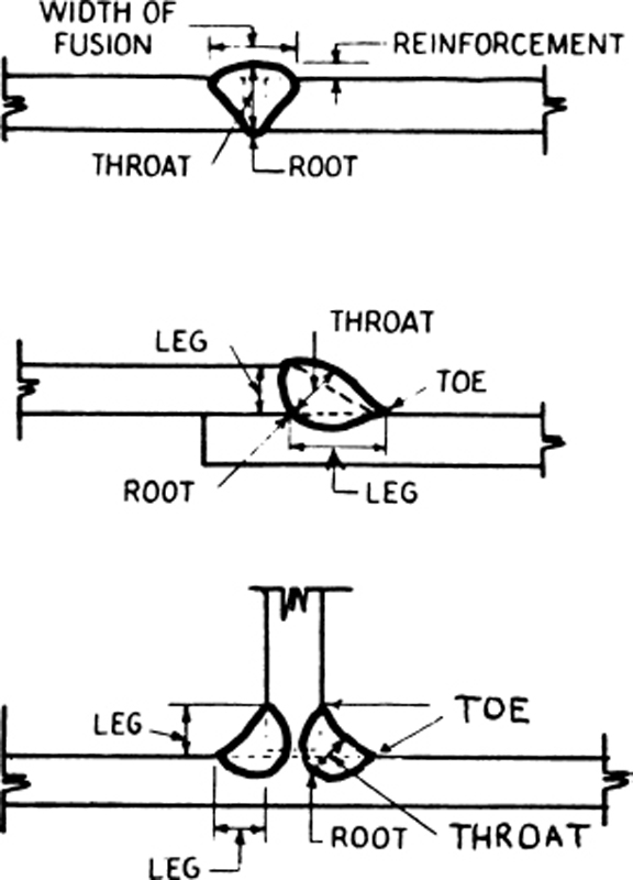
FIGURE 6-3 Details of weld nomenclature.
Proportions of a Weld
The three most important proportions of a weld are (1) the depth of penetration, which should be at least one-fourth the thickness of the base metal; (2) the width of the bead, which should be between two and three times as great as the thickness of the base metal; and (3) the height of the reinforcement, which should be not less than one-half the thickness of the base metal. Note that these dimensions should be considered minimums and are less than the recommended values shown in the various figures included in this chapter.
In Fig. 6-4, the butt weld shown in drawing 1 has a bead that is three to five times the thickness of the base metal. In attaching an aircraft fitting by means of a lap weld, as in drawing 2 of Fig. 6-4, the width of the fillet bead is 1 times the thickness of the upper sheet. In making a tee joint, as in drawing 3, the weld bead has a thickness through the throat that equals the thickness of the vertical member. The penetration of the weld into the sides of the joint is one-fourth the thickness of the base metal, and the height of the reinforcement meets the requirements previously given.
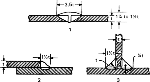
FIGURE 6-4 Preferred dimensions of a weld.
Correct Formation of a Weld
A weld must be formed correctly to provide strength and to resist fatigue in a joint. If it is not made properly, the weld may have less than 50 percent of the strength for which the joint was designed. Figure 6-5 shows correct lap joints; Fig. 6-6 shows correct tee joints; Fig. 6-7 shows good corner joints; and Fig. 6-8 illustrates properly formed butt joints.

FIGURE 6-5 Properly made lap joints.
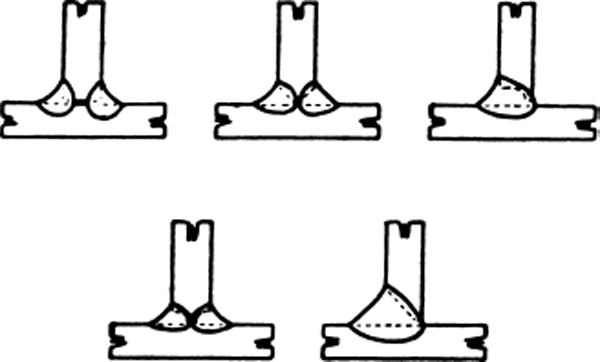
FIGURE 6-6 Correct tee joints.

FIGURE 6-7 Good corner joints.

FIGURE 6-8 Properly formed butt joints.
The typical causes of improperly formed weak welds are (1) undercutting of the base metal at the toe of the weld; (2) not enough penetration; (3) poor fusion of the weld metal with the base metal; (4) trapped oxides, slag, or gas pockets in the weld; (5) overheating of the weld; and (6) overlap of the weld metal on the base metal. These incorrect conditions result from inexperience, poor technique, or carelessness. Figure 6-9 shows a large number of faults commonly found in the weld-metal formation of various joints. Any weld that has an appearance similar to one of the drawings in this illustration should be rejected.
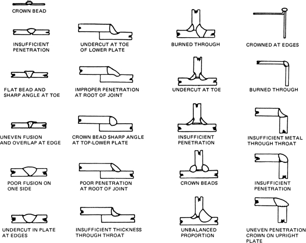
FIGURE 6-9 Common faults in welding.
Chemical Changes Produced by Welding
A chemical change occurs when a substance is added to or taken from a metal. The heat of the welding process will cause the loss of one or more of the chemical constituents of a piece of metal if the heat remains on the metal for any length of time; this loss usually will result in a reduction of such physical properties of the metal as tensile strength, ductility, and yield point. Also, if some element is added to the metal during the welding process or if there is some material change in one or more of the chemical constituents, the change will usually lower the strength of the metal.
Physical Changes Produced by Welding
A physical change is a change of any kind that takes place without affecting the chemical structure of a metal. Some of the physical changes most important in welding are changes in the melting point, heat conductivity, and rate of expansion and contraction.
The melting point is the degree of temperature at which a solid substance becomes liquid. Pure metals have a melting point, but alloys have a melting range. Welders should know the approximate melting points of the various metals with which they work because they must often weld together metals that have widely different melting points. If a metal includes an alloyed element, the melting point is lowered; hence the melting points given in tables for alloyed metals vary according to the proportion of alloying elements present and should be considered with this fact in mind.
Some physical changes take place in the materials being welded because the application of heat during the welding process results in expansion and contraction of the materials. The technician should keep in mind the difference between temperature and heat. Put simply, heat is the quantity of a temperature that is available. Heat is measured in British thermal units (BTUs), whereas temperature is measured in degrees.
Expansion is an increase in the dimensions (length, width, thickness) of a substance under the action of heat. If a metal structure is unevenly heated, there will be an uneven expansion, and this will produce distortion (warping) and possibly breakage. On the other hand, if the temperature is raised progressively throughout the whole mass of the object, the action is uniform and there is no distortion or breakage.
Applying this to welding, if the heat from the welding process is concentrated at one point on a metal object, the metal in the heated area tends to expand where the heat is applied, and the portion that opposes this expansion may be distorted, cracked, or severely strained.
Tables giving the properties of metals usually include the coefficients of expansion. A coefficient of thermal expansion of any metal is the amount that the metal will expand per inch for each degree rise in temperature. For example, aluminum has a coefficient of expansion of 0.000 012 34, whereas steel has a coefficient of expansion of 0.000 006 36. This shows that aluminum expands more than steel for each degree rise in temperature. In both these cases, the coefficient refers to a rise of 1°F [0.5556°C].
To apply this knowledge, a simple formula can be used. Let A represent the length in inches of the piece of metal, B the temperature in degrees Fahrenheit, and C the coefficient of expansion. Then, expansion in inches = A × B × C. Thus, if a piece of aluminum is l in [2.54 cm] long, is raised in temperature 1°F [0.5556°C), and has a coefficient of expansion of 0.000 012 34, then the expansion is 1 × 1 × 0.000 012 34, or 0.000 012 34 in [0.000 031 2 cm].
Contraction is the shrinking of a substance when cooled. It is the reverse of expansion. Unless there is some restraint, materials contract as much when cooled as they expanded when they were heated, assuming that the temperature is uniform throughout.
In a trussed frame, whether it is in an airplane or a bridge, there is a restriction of the free movement of the metal parts. When such restrictions are present and the metal is malleable (capable of being worked into shape by hammering, rolling, or pressing), warping will take place. If the metal is brittle, it will usually crack. If the piece of metal is “open,” that is, if no obstructions or restrictions hinder its free expansion and contraction, there is no danger of its being damaged from expansion and contraction. An example of open metal occurs in the case of an ordinary bar of metal, a length of unattached tubing, or some similar detached piece of metal.
If the metal is “closed,” as in Fig. 6-10, there is danger from expansion and contraction. The bar that was formerly free and unattached is now the center section in Fig. 6-10, and it is fastened rigidly to a solid frame. If the break marked with the letters A and B in Fig. 6-10 is welded, provision must be made for expansion and contraction. Since the crosswise and lengthwise members of the frame are rigid, they do not permit the ends of the bar in the center to expand; hence, the only place where expansion can take place while the metal is heated during the welding process is at the point of the weld. When this portion begins to cool, the center bar contracts and shortens, but the frame in which it is placed refuses to surrender to the inward pull of the ends of the center bar. Warping occurs along the line of weld, or possibly a break occurs.
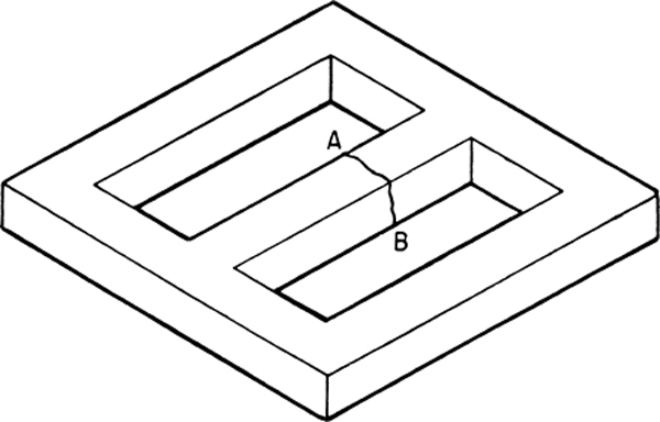
FIGURE 6-10 Welding a closed section requires heating of the entire closed area.
To avoid this damage, a trained welder heats the whole object before attempting to weld the break in the center piece. The whole object expands equally, pulling apart the edges of the break. The welder makes the weld and allows the object to cool. It all cools to the same extent, contracts equally, and suffers neither warpage nor breakage. Figure 6-11 shows examples of shrinkage in welded metal objects.
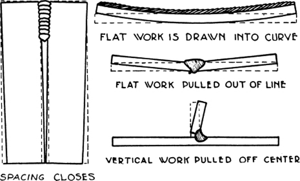
FIGURE 6-11 Shrinkage of metal caused by welding.
Conductivity
Conductivity is the physical property of a metal that permits the transmission of either an electric current, called electrical conductivity, or heat, called thermal conductivity, through its mass. The rate of conductivity is the speed at which a metal body will transmit either an electric current or heat through its mass. The rate of conductivity varies among metals. Radiation (heat loss) influences both the rate of heat conductivity and the area that will be affected by heat conductivity. Thus, metals that are good heat conductors may be poor radiators, and those that are good radiators may be poor conductors.
In welding, a considerable amount of heat is carried away from the point of application and is lost to the surrounding environment. For this reason, metals that have a high thermal conductivity require more heat in welding than those with a low conductivity, other things being equal.
Another thing to remember in welding is that the higher the thermal conductivity, the more extensive and the hotter will become the heated area around the weld. Therefore, more expansion can be expected with metals of high thermal conductivity, other things being equal.
Effect of High Temperatures on the Strength of Metals
Some metals have absolutely no strength or almost no strength when they are raised to extremely high temperatures. In some cases, this temperature may be far below the melting point of the metal. For example, aluminum alloys, brass, bronze, copper, cast iron, and certain alloy steels become very brittle at high temperatures near their melting points. If such metals are strained while at these high temperatures, they will break, or check, in the area that has been heated.
For example, the melting point of aluminum is 1218°F [659°C]. At 210°F [99°C], it has 90 percent of its maximum strength; at 400°F [204°C], it has 75 percent; at 750°F [399°C], it has 50 percent; at 850°F [454°C], it has 20 percent; and at 930°F [499°C], it has only 8 percent of its maximum strength. Yet at 930°F [499°C], it is still far below the melting point.
OXYACETYLENE WELDING
Oxyacetylene Welding Equipment
Oxyacetylene welding equipment may be either portable or stationary. A portable apparatus can be fastened on a hand truck or cart and pushed around from job to job. It consists of one cylinder containing oxygen; another containing acetylene; acetylene and oxygen pressure regulators, complete with pressure gauges and connections; a welding torch with a mixing head, tips, and connections; two lengths of colored hose, with adapter connections for the torch and regulators; a special wrench; a pair of welding goggles; a safety flint and file gas lighter; and a fire extinguisher. Figure 6-12 shows a portable welding outfit.
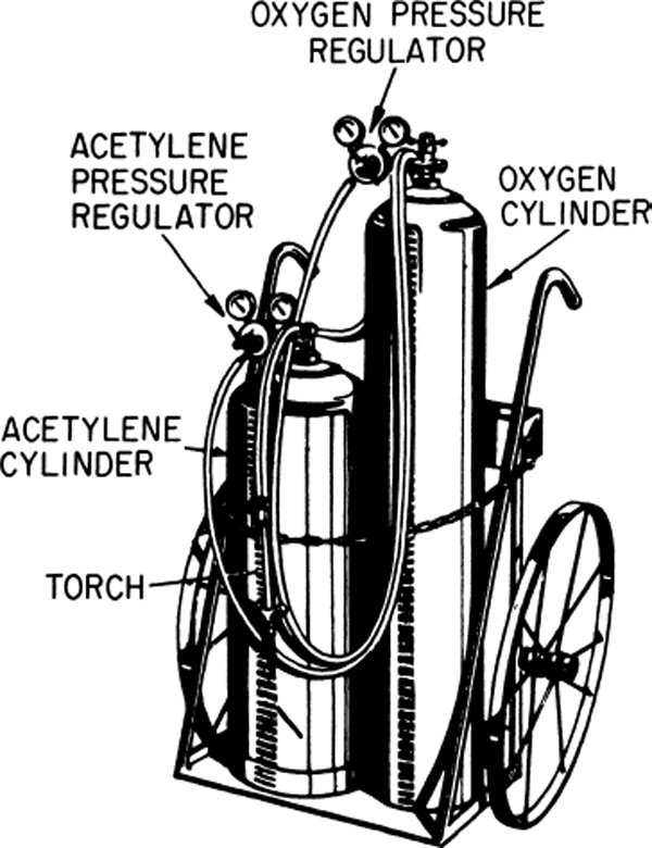
FIGURE 6-12 A portable welding outfit.
Stationary equipment is used where several welding stations are located close to each other and the stations can be supplied with gases through a manifold system. The oxygen and acetylene cylinders, located in areas separate from each other for safety, feed into the appropriate manifold through a master regulator. The master regulator sets the maximum pressure for the manifold. Each work station has a line regulator so that the welder can set the pressure as necessary for the particular task. In some shops, the acetylene does not come from cylinders. Instead, it is piped directly from an acetylene generator, an apparatus used for producing acetylene gas by the reaction of water upon calcium carbide.
Acetylene
Acetylene is a flammable, colorless gas with a distinctive odor that is easily detected, even when strongly diluted with air. It is a compound of carbon and hydrogen having the chemical symbol C2H2, which means that two atoms of carbon are combined with two atoms of hydrogen.
When acetylene is mixed with air or oxygen, it forms a highly combustible gas. It has a flame spread of 330 ft/s [99 m/s]. To prevent it from burning back to the source of supply during welding, the acetylene, when mixed with air or oxygen, must flow from the torch at a velocity greater than the flame spread, or the absorption of heat by the torch tip must be sufficient to prevent the flame from entering the tip.
Under low pressure at normal temperature, when free from air, acetylene is a stable compound; however, when it is compressed in an empty container to a pressure greater than 15 psi [103 kPa], it becomes unstable. At 29.4 psi [202.74 kPa) pressure it becomes self-explosive, and only a slight shock is required to cause it to explode even when it is not mixed with air or oxygen. As a general rule, the technician should never allow the acetylene pressure in the welding system to exceed 15 psi [103 kPa].
Although this gas is highly explosive, it is shipped in cylinders under high pressure with a high degree of safety. This is possible because the manufacturers place a porous substance inside the acetylene cylinder and then saturate this substance with acetone, which is a flammable liquid chemical that absorbs many times its own volume of acetylene. A cylinder containing a correct amount of acetone can be charged to a pressure of more than 250 psi [1724 kPa] with safety under normal conditions of handling and temperature.
Acetylene cylinders are available in several sizes, holding up to 300 ft3 [8.5 m3] of gas at a maximum pressure of 250 psi [1724 kPa]. The cubic feet of acetylene gas in a cylinder may be found by weighing the cylinder and subtracting the tare weight stamped on the cylinder from the gross weight; that is, the weight of an empty cylinder is subtracted from the weight of a charged cylinder. The difference is in pounds; this figure is multiplied by the weight of acetylene, 14.5 ft3/lb [411 L per 0.454 kg], to obtain the number of cubic feet in the cylinders. Figure 6-13 is an exterior view of an acetylene cylinder.

FIGURE 6-13 An acetylene cylinder. (Linde Div., Union Carbide Corp.)
Oxygen
Oxygen is a tasteless, colorless, odorless gas that forms about 23 percent by weight and about 21 percent of volume of the atmosphere. Oxygen is an extremely active element. It combines with almost all materials under suitable conditions, sometimes with disastrous results. For example, grease and oil are highly combustible in the presence of pure oxygen; hence it is important to avoid bringing pure oxygen into contact with oil or grease. Such a mixture of oxygen and oil can produce a violent explosion. There are recorded cases of welders being killed by turning a stream of pure oxygen into a can of grease. Even grease spots on clothing may lead to explosions if they are struck by a stream of oxygen. Oxygen is necessary to make acetylene burn at a temperature high enough to melt metal in welding. In technical language, oxygen supports the combustion of the gas used in producing the welding flame.
The standard cylinder for storing and shipping oxygen gas for welding and cutting purposes is a seamless, steel, bottle-shaped container like the one shown in Fig. 6-14. It is made to withstand exceedingly high pressures. Although an acetylene cylinder is normally charged at a pressure of 250 psi [1724 kPa] at a temperature of 70°F [21.1°C], an oxygen cylinder is initially charged at the plant to a pressure of 2200 psi [ 15 171 kPa] at a temperature of 70°F [21.1°C].
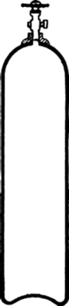
FIGURE 6-14 An oxygen cylinder.
Two sizes of oxygen tanks are generally available. The standard size is a cylinder having a capacity of 220 ft3 [6.23 m3]; the small cylinder has a capacity of 110 ft3 [3.11 m3]. Since the weight of oxygen is 0.08926 lb/ft3 [1.43 kg/m3], 11.203 ft3 [0.32 m3] equal 1 lb [0.4536 kg]. To find the quantity of oxygen in a cylinder, simply subtract the weight of an empty cylinder from the weight of a charged cylinder, and multiply the number of pounds by 11.203 to obtain the cubic feet of oxygen in the cylinder.
Figure 6-15 shows the construction of an oxygen cylinder valve assembly. A safety device (bursting disk) is contained in the nipple at the rear of the valve and consists of a thin copper-alloy diaphragm. When the cylinder is not in use, the valve is covered with a protector cap. This is an important feature in preventing the valve from being broken in handling.
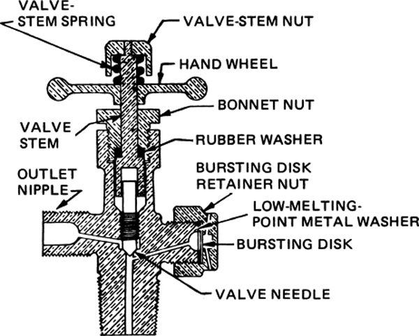
FIGURE 6-15 An oxygen cylinder valve.
Acetylene and Oxygen Regulators
Acetylene and oxygen regulators are mechanical instruments used to reduce the high pressure of the gases flowing from their containers and to supply the gases to the torch at a constant pressure and volume, as required by the torch tip or nozzle. Almost all regulators are available for either single-stage or two-stage pressure reduction.
In an installation where the gases are piped to the individual welding stations, only one gauge is required for each welding station, because it is necessary only to indicate the pressure of the gas flowing through the hose to the torch.
Regulators on cylinders are usually equipped with two pressure gauges. A high-pressure gauge shows the pressure of the gas in the cylinder, and a low-pressure gauge indicates the pressure of the gases flowing to the torch.
The high-pressure gauges on oxygen regulators are graduated in pounds per square inch from 0 to 3000. The low-pressure, or working, gauge for oxygen-welding regulators is usually graduated in pounds per square inch from 0 to 100, 0 to 200, or 0 to 400. Figure 6-16 shows oxygen-pressure gauges mounted on a pressure regulator.
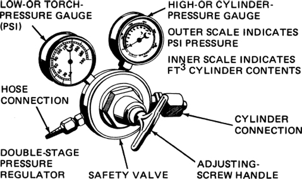
FIGURE 6-16 Oxygen-pressure gauges on the regulator.
Figure 6-17 shows acetylene-pressure gauges mounted on a pressure regulator. Acetylene regulators are designed in a manner similar to oxygen regulators, but they are not required to withstand such high pressures. The high-pressure gauge for acetylene indicates pressures up to a maximum scale value of only 400 psi. The maximum scale values on various low-pressure, or working, gauges range from 30 to 50 psi and the dial graduations have values of to 2 psi, depending upon the purpose for which the gauge is to be used.
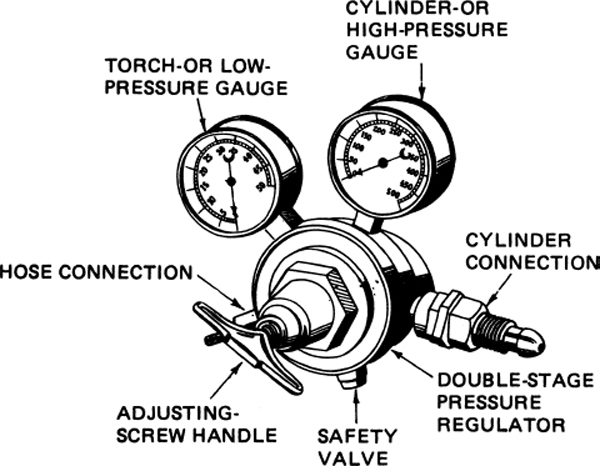
FIGURE 6-17 Acetylene-pressure gauges on the regulator.
Welding Torches
A welding torch is a device used to mix oxygen and acetylene together in the correct proportions and to provide a means of directing and controlling the quality and size of the flame. The welding gases flow from the inlet ports, past needle valves, through tubes in the torch to a mixing valve and then through the tip. Needle valves are used to regulate the volumes of acetylene and oxygen that flow into the mixing head. The torch head is usually located at the forward end of the handle. The mixing head is seated in the torch head and extends beyond the torch head. As its name indicates, the purpose of the mixing head is to provide for the correct mixing of the gases for the best burning conditions. The mixture of oxygen and acetylene flows from the mixing head into the tip of the torch and then emerges at the end of the tip, where it is ignited and burns to provide the welding flame. Some welding torches use the oxygen flow to help dissipate the heat absorbed by the torch during the welding process by routing the oxygen passage through the torch; then the passageway acts as a cooling coil.
Welding torches may be divided into two principal types: (1) the balanced-pressure type, sometimes called the equal-pressure type, illustrated in Figs. 6-18 and 6-19, and (2) the injector type, illustrated in Figs. 6-20 and 6-21. These torches are available in different styles and sizes, and they are obtainable for use with several tip sizes, which are interchangeable. The selection of the style and size of the torch depends upon the class of work to be done. The selection of the tip size depends upon the amount of heat and the size of the flame required for the kind and thickness of the metal to be welded.
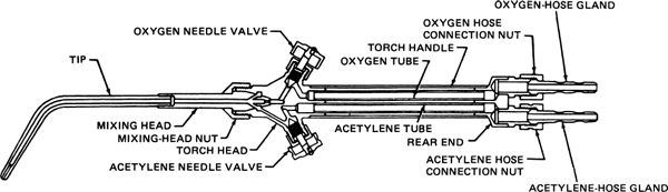
FIGURE 6-18 Cutaway drawing of a balanced-type welding torch.
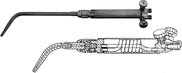
FIGURE 6-19 Photo of a balanced-type torch with a cutaway drawing to show cooling coil. (Linde Div., Union Carbide Corp.)
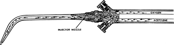
FIGURE 6-20 Injector-type welding torch.

FIGURE 6-21 Mixing head for injector-type welding torch.
The primary difference to be considered in selecting balanced-pressure type or an injector-type welding torch is the source of the acetylene gas. If the acetylene gas is obtained from an acetylene generator, the pressure in the acetylene lines will be low. When the acetylene comes from cylinders the pressure is comparatively high. Balanced-pressure-type torches are used where the acetylene source pressure is high. The injector-type torch uses the velocity of the oxygen to cause a low-pressure effect that draws the necessary amount of acetylene into the mixing chamber, where the acetylene and oxygen are thoroughly mixed and directed to the tip.
Tip nozzles may have a one-piece hard copper tip or they may have a two-piece tip that includes an extension tube to make the connections between the mixing head and the tip. Welding tips are made in a variety of sizes and styles. Removable tips are made of either hard copper or of an alloy such as brass or bronze. The tip sizes differ in the diameter of the orifice, which provides the correct amount of gas mixture at a velocity that will produce the heat necessary to do the job.
Both the velocity and volume of gases are important. Velocity is important because it regulates the amount of heat that the technician will be able to apply to the material to be welded. The temperature is regulated by the mixing head, but the amount of that temperature or heat (measured in BTUs) is regulated by the velocity of the gases.
Too low a velocity will also allow the flame to burn back into the tip and cause a “pop” (backfire), which will blow the flame out. This will also happen if the tip gets too hot.
The manufacturer of the welding equipment supplies a table giving the approximate pressure of acetylene and oxygen for the various-size tips for an equal-pressure torch and a similar table for an injector-type torch. The torch tips should be of a proper size for the thickness of the material and the type of intersection involved. Tip sizes are designated by numbers, and each manufacturer has an individual system of numbering. Some manufacturers designate tip sizes by 0, 1, 2, 3, 4, etc., and others start with a higher number such as 20, 21, or 22. The commonly used sizes for working on steel butt welds are given in Table 6-2.
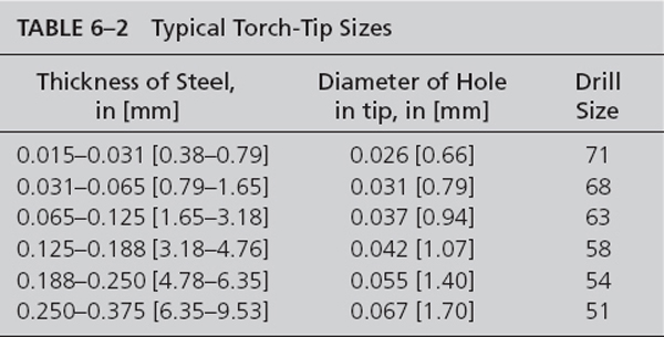
For any given thickness of steel or steel alloys, the heat required varies according to the angle of intersection. For example, the heat required for two pieces of metal of the same thickness intersecting at an angle of 30° is different than the heat required for welding the same two pieces intersecting at an angle of 90°.
It is important to select a small tip for light work and a larger tip for heavy work, because the size of the tip determines the amount of heat applied to the metal. If a small tip is used for heavy work, there is not enough heat to fuse the metal at the right depth. If the tip is too large, the heat is too great, and holes will be burned in the metal.
Cleaning the Torch Tip
Small particles of carbon, oxides, and metal can be removed from the tip of a welding torch with a soft copper wire, a drill of the correct size, a tip cleaner manufactured for the purpose, shown in Fig. 6-22, or any other suitably shaped device that will not damage the tip. Care must be taken to maintain a smooth, round orifice through which the gases can emerge.

FIGURE 6-22 Tip cleaner. (Linde Div., Union Carbide Corp.)
If the tip becomes worn to the extent that the opening of the orifice flares out or is bell-shaped, the end of the tip should be ground square on a piece of fine emery cloth held flat against a smooth surface. The tip should be held perpendicular to the surface of the emery cloth and moved back and forth with straight strokes.
The outside surface of the tip can be cleaned with fine steel wool to remove carbon, oxides, and particles of metal. After the outside is cleaned, the orifice should be cleaned to remove any material that may have entered.
Welding Hose
A welding hose is a specially made rubber or synthetic rubber tube attached to the torch at one end and to a pressure regulator at the other end. It is used to carry the gases from their containers to the torch.
Several techniques are used in combination to prevent the oxygen and acetylene hoses from being connected to the wrong regulator or the wrong fitting on the torch. The acetylene hose is usually red or maroon in color, the threads on the fittings are left-handed, the fittings normally have a groove cut around the middle of the wrenching surface, and the word ACETYLENE may be found on the hose or the letters ACE may be found on the fittings. The oxygen hose is normally green in color, the fittings are right-handed with no groove on the wrenching surface, and the word OXYGEN may be found on some hoses or the letters OXY may be on the fittings. Figure 6-23 illustrates typical acetylene- and oxygen-hose connections to show the difference.

FIGURE 6-23 Acetylene- and oxygen-hose connectors.
Welding hoses and fittings should be examined regularly to see that the hoses are in good condition and that the fittings are not worn or damaged to the extent that they allow leakage of gases.
Welding, or Filler, Rod
The welding rod, sometimes called a filler rod, is filler metal, in wire or rod form, drawn or cast, used to supply the additional metal required to form a joint. During welding, the rod is melted into the joint, where it fuses with the molten base metal, the metal from the rod forming a large proportion of the actual weld metal. Welding rods are usually composed of only one metal or alloy, although rods known as composite rods contain more than one metal. If a rod has a very small diameter, it is usually known as a wire.
In selecting welding rod or wire for a particular application, the technician must be certain that the rod will be compatible with the material being welded and that the rod material will respond properly to any heat-treatment process required after the weld is completed. Additionally, some rods are available with coatings or flux to prevent contamination of welds, and other rods, such as those used for common steel applications, are coated with copper to prevent the rod from rusting.
Welding rods are 3 ft [0.91 m] long and come in several diameters, ranging from  in [1.59 mm] to
  in [6.35 mm]. The size of the rod must be matched to the size of the material being welded. The diameter of the rod used is often the same as the thickness of the material being welded. Manufacturers of welding rods can provide specific information about their products to aid the technician in selecting the correct rod material and diameter for a specific welding application.
Safety Equipment
Welding goggles, such as those shown in Fig. 6-24, are fitted with colored lenses to keep out heat and the ultraviolet and infrared rays produced during welding. Clear lenses are provided in front of the colored lenses to protect the colored lenses from damage. The goggles should hug the face so closely that sparks and tiny pieces of hot metal cannot get inside.
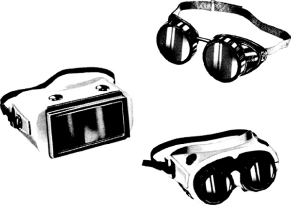
FIGURE 6-24 Welding goggles. (Linde Div., Union Carbide Corp.)
Figure 6-25 shows a pair of welding gloves, commonly described as the gauntlet style. The material, manufacturing quality, and fit must be such that the gloves protect the hands and wrists from burns and flying sparks. They are usually made of asbestos or of chemically treated canvas.
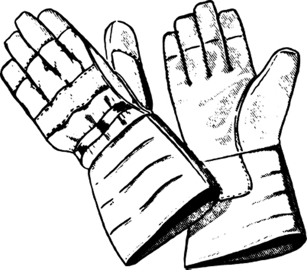
FIGURE 6-25 Welding gloves.
Figure 6-26 shows a device that has several names. It may be called an igniter, friction lighter, safety lighter, or spark lighter. It is a hand-operated device used to light a gas torch safely. It consists of steel, a flint, a shield, and a spring. The steel, usually placed in a cup-shaped shield, resembles a file and is attached to the other end of the spring. The technician grasps the spring in one hand and compresses and releases the spring, forcing the flint to rub across the steel, thus producing sparks that light the gas coming out of the torch. This device is safe because it is composed of non-combustible material, the spark burns only for a fraction of a second, and the lighter is long enough to protect the welder’s hand from the flame when properly used.
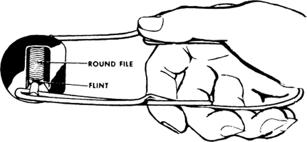
FIGURE 6-26 A friction lighter for welding torches.
Stationary welding benches are often equipped with a pilot flame by which the welder may light the torch. If the torch should blow out while the welder is adjusting it or while welding, it is necessary merely to pass the tip of the torch over the pilot flame to reignite it.
Never use cigarette lighters or matches. Always use the spark lighter just described or a pilot flame. If a cigarette lighter or matches are used, the puff of the flame from the torch may burn the hand.
One or more portable fire extinguishers are kept at hand to be used if the flame from the welding torch, flying sparks, or flying pieces of hot metal set fire to anything. Carbon dioxide is generally the fire-extinguishing medium used because it is effective in combating gasoline or oil fires and may be used on wood and fabric fires. Carbon dioxide is often combined with a chemical powder, which aids in extinguishing fires.
Setting Up Oxyacetylene Welding Equipment
In order for efficient welding to take place, the equipment must be set up properly. This will allow a proper torch flame to be created, afford the maximum safety for the operator, and prevent unnecessary wear or damage to the equipment. In this discussion, the general procedures used for a portable system are addressed, but the basic procedures discussed are also applicable to a stationary system. When working with specific welding equipment, always follow the equipment manufacturer’s procedures and recommendations.
Assembling the System
The first step in setting up portable welding apparatus is to fasten the cylinders to the cart or hand truck. The purpose of this step is to prevent the cylinders from being accidentally pulled or knocked over. The protecting cap that covers the valve on the top of the cylinder is not removed until the welder is ready to make a connection to the cylinder.
The second step in setting up the apparatus is to “crack” the cylinder valves. The welder stands beside or behind the cylinder outlet, as shown in Fig. 6-27, and opens the cylinder valve slightly for a moment and then quickly closes it. The purpose of this step is to clear the valve of dust or dirt that may have settled in the valve during shipment or storage. Dirt will cause leakage if it gets into the regulator, and it will mar the seat of the regulator inlet nipple even if it does not actually reach the regulator.

FIGURE 6-27 Correct position for the operator when opening the cylinder valve.
The third step is to connect the regulators to the cylinders. The welder uses a tight-fitting wrench to turn the union nut, as shown in Fig. 6-28, and makes certain that the nut is tight so that the gas will not leak.

FIGURE 6-28 Wrench in position for tightening the union nut.
The fourth step is to connect the hoses to their respective regulators. The green hose is connected to the oxygen regulator and the red hose is connected to the acetylene regulator. With the cylinder valves open, the regulator adjustment handles should be turned clockwise a sufficient amount to blow gas through the hoses and clear any dust or dirt. The handles are then turned counterclockwise until there is no pressure on the diaphragm spring and the cylinder valves are closed.
The fifth step is to connect the hoses to the torch, as shown in Fig. 6-29. The acetylene fitting, identified by the groove around the nut, has a left-hand thread and, therefore, will fit only the acetylene fitting on the torch. A tight-fitting wrench should be used to avoid damage to the nuts.
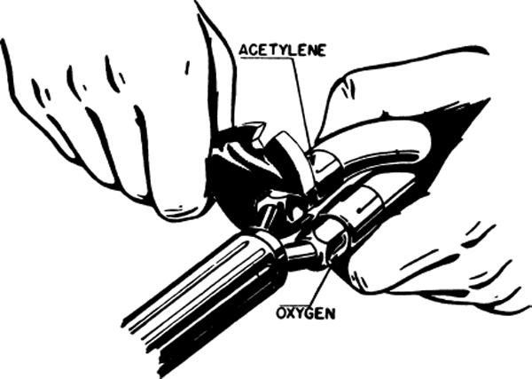
FIGURE 6-29 Connecting the gas hose to a torch.
The sixth step in setting up the welding equipment is to test for leaks. This should not be done by using a lighted match at the joints. No open flame should be allowed in the vicinity of welding equipment except for the flame of the torch. There are several ways to test for leaks, but the best method is to apply soapy water to the joints with a brush. Before making this test, the oxygen and acetylene needle valves on the torch are closed. The cylinder valves are opened, and then the regulator adjusting screws are turned to the right (clockwise) until the working gauges show only a low pressure. The brush is dipped in the soap solution, and the solution is spread evenly over the connections. A leak is indicated by a soap bubble.
If a leak is discovered, the welder should close the cylinder valves and search for the source of trouble. It is generally sufficient to tighten the connecting unit slightly in order to stop the leak. Less common sources of trouble are dirt in the connection, which must be cleaned out, or marred seats or threads in the connection. If the seats or threads are damaged, the connections should be replaced. Having removed the trouble causing a leak, the welder must again test for leaks to be absolutely certain that none exist.
Ordinarily, the welder knows the correct tip size for the work to be done, a small opening for thin metal or a larger opening for thick metal being provided. On the assumption that the apparatus is set up, the next job is to adjust the working pressure of the gases.
Setting the Pressure
Figure 6-27 shows a welder in the correct position for opening the cylinder valve, regardless of whether the cylinder has a regulator attached or not. When a regulator is installed on the cylinder, the operator stands behind or to the side of the regulator and opens the valve slowly. If the regulator is defective, pressure may build up behind the glass and cause it to burst. This would be likely to inflict injury on anyone standing in the area immediately in front of the regulator.
When ready to open the cylinder valves, the welder should open the acetylene cylinder valve about one complete turn and open the oxygen valve all the way, slowly in both cases. If a valve wrench is used on the acetylene valve, this should be left on the valve so that the acetylene flow can be turned off quickly if a flame appears at a fitting or at a hose rupture. Then the welder sets the working pressure for the oxygen and the acetylene by turning the adjusting screw on the regulator to the right (clockwise) until the desired pressure reading is obtained on the gauge. As mentioned before, the exact pressure required for any job primarily depends upon the thickness of the metal, and this determines the size of the welding tip used. Remember, do not allow the acetylene pressure in the hose to exceed 15 psi.
Lighting the Torch
To light the torch, the welder opens the acetylene needle valve on the torch three-quarters of a turn and then uses the spark lighter to light the acetylene as it leaves the tip. The welder should do this as quickly as possible in order to prevent a large cloud of gas from developing. The flame should be large, very white, and smoky on the outer edges. If the flame produces much smoke, the welder should “crack” the oxygen needle valve very slightly and as soon as the flame appears to be under control, continue slowly to open the oxygen needle valve until a well-shaped bluish-white inner cone appears near the tip of the torch. This cone is surrounded by a second outer cone or envelope that varies in length, depending upon the size of the welding tip being used. This is known as a neutral flame and is represented by the upper drawing in Fig. 6-30.
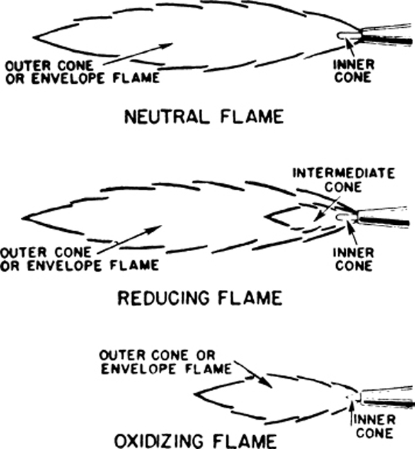
FIGURE 6-30 Neutral, reducing, and oxidizing flame.
Oxyacetylene Flames
A welding flame is called neutral when the gas quantities are adjusted so all the oxygen and acetylene are burned together. Theoretically, 2 volumes of oxygen are required to burn 1 volume of acetylene in order to produce this neutral flame, but actually it is only necessary to provide 1 volume of oxygen through the torch for 1 volume of acetylene consumed, because the remainder of the required oxygen is taken from the atmosphere. The carbon monoxide and hydrogen gas that come out of the first zone of combustion combine with oxygen from the air to complete the combustion, thus forming carbon dioxide and water vapor.
The neutral flame produced by burning approximately equal volumes of acetylene and oxygen oxidizes all particles of carbon and hydrogen in the acetylene, and it has a temperature of about 6300°F [3482°C]. This neutral flame should have a well-rounded, smooth, clearly defined, blue-white central cone. The outer cone, or envelope, flame should be blue with a purple tinge at the point and edges.
A neutral flame melts metal without changing its properties and leaves the metal clear and clean. If the mixture of acetylene and oxygen is correct, the neutral flame allows the molten metal to flow smoothly, and few sparks are produced. If there is too much acetylene, the carbon content of the metal increases, the molten metal boils and loses its clearness, and the resulting weld is hard and brittle. If too much oxygen is used, the metal is burned, there is a great deal of foaming and sparking, and the weld is porous and brittle.
A neutral flame is best for most metals. However, a slight excess of one of the gases may be better for welding certain types of metal under certain conditions. For example, an excess of acetylene is commonly used with the nickel alloys Monel and Inconel. On the other hand, an excess of oxygen is commonly used in welding brass.
A carburizing, or reducing, flame is represented by the middle drawing of Fig. 6-30. This occurs when there is more acetylene than oxygen feeding into the flame. Since the oxygen furnished through the torch is not sufficient to complete the combustion of the carbon, carbon escapes without being burned. There are three flame zones instead of the two found in the neutral flame. The end of the brilliant white inner core is not as well defined as it was in the neutral flame. Surrounding the inner cone is an intermediate white cone with a feathery edge, sometimes described as greenish-white and brushlike. The outer cone, or envelope, flame is bluish and similar to the outer cone, or envelope, flame of the neutral flame.
An oxidizing flame is represented by the lower drawing of Fig. 6-30. It is caused by an excess of oxygen flowing through the torch. There are only two cones, but the inner cone is shorter and more pointed than the inner cone of the neutral flame, and it is almost purple. The outer cone, or envelope, flame is shorter than the corresponding portion of either the neutral flame or of the reducing flame and is of a much lighter blue color than the neutral flame. In addition to the size, shape, and color, the oxidizing flame can be recognized by a harsh, hissing sound, similar to the noise of air under pressure escaping through a very small nozzle.
The oxidizing flame is well named. It oxidizes, or burns, most metals, and it should not be used unless its use is definitely specified for some particular purpose. Since an oxidizing flame is generally objectionable, the welder must examine the flame every few minutes to be sure of not getting an oxidizing flame. The welder does this by slowly closing the torch oxygen valve until a second cone or feathery edge appears at the end of the white central cone and then opening the oxygen valve very slightly until the second cone disappears.
Figure 6-31 shows a neutral or oxidizing flame with an irregular-shaped outer cone, or envelope—flame produced by an obstructed tip. When this flame is discovered, the welder should immediately shut down the welding apparatus and either clean the tip or replace it.
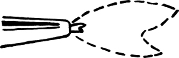
FIGURE 6-31 Flame produced by an obstructed tip.
After learning to adjust the flame so that the proportions of oxygen and acetylene are correct, the welder must then learn how to obtain a soft flame. This flame is produced when the gases flow to the welding tip at a comparatively low speed. If the gases flow to the welding tip at a comparatively high speed, under too much pressure, they produce a harsh flame that is easily recognized because it is noisy. A harsh flame destroys the weld puddle and causes the metal to splash around the edges of the puddle. It is very difficult to get the metal parts to fuse properly with a flame of this kind.
If the mixture of acetylene and oxygen and the pressure are correct, the welder may still fail to obtain a soft neutral flame if the welding tip is dirty or obstructed in any manner. An obstructed welding tip does not permit the gas mixture to flow evenly, and it restricts the source of heat required to melt the metal; therefore, a good weld is very difficult to produce.
If there is any fluctuation in the flow of the gases from the regulators, the mixture will change, regardless of other conditions; hence a good welder watches the flame constantly and makes any necessary adjustments to keep it neutral and soft.
Backfire and Flashback
A backfire is a momentary backward flow of gases at the torch tip, causing the flame to go out and then immediately to come on again. A backfire is always accompanied by a snapping or popping noise. Sometimes the word backfire is used loosely to mean flashback, but a true backfire is not as dangerous as a flashback, because the flame does not burn back into the torch head and does not require turning off the gases.
There are five common causes of backfires: (1) there may be dirt or some other obstruction in the end of the welding tip; (2) the gas pressures may be incorrect; (3) the tip may be loose; (4) the tip may be overheated; or (5) the welder may have touched the work with the tip of the torch or allowed the inner cone of the flame to touch the molten metal (puddle).
If the tip is dirty or obstructed, it is removed and cleaned or replaced. If the gas pressures are wrong, they are adjusted. If the tip is loose, the torch is turned off and the tip tightened. If the tip is overheated, the torch is turned off and allowed to cool. If the tip touches the work or the inner cone contacts the puddle, the welder merely avoids repeating the error.
Flashback is the burning back of the flame into or behind the mixing chamber of the torch. Where flashback occurs, the flame disappears entirely from the tip of the torch and does not return. In some instances, unless either the oxygen or the acetylene or both are turned off, the flame may burn back through the hose and pressure regulator into the gas supply (the manifold or the cylinder), causing great damage. Flashback should not be confused with backfire, as explained previously. The welder must always remember that if a flashback occurs, there will be a shrill hissing or squealing, and the flame will burn back into the torch. The welder must quickly close the acetylene and oxygen needle valves to confine the flash to the torch and let the torch cool off before lighting it again. Since a flashback extending back through the hoses into the regulators is a symptom of something radically wrong, either with the torch or with the manner of its operation, the welder must find the cause of the trouble and remedy it before proceeding. Flashback arrestor valves can be installed on each hose to prevent a high-pressure flame or oxygen-fuel mixture from being pushed back into either cylinder causing an explosion. The flashback arrestors incorporate a check valve that stops the reverse flow of gas and the advancement of a flashback fire. The flashback arrestor valve is installed between the hose and torch or between the hose and the regulator. Figure 6-32 shows a flashback arrestor valve.

FIGURE 6-32 Flashback arrestor valve.
Shutting Down the Welding Apparatus
The procedure for shutting down the welding apparatus is as follows:
1. Close the acetylene needle valve on the torch to shut off the flame immediately.
2. Close the oxygen needle valve on the torch.
3. Close the acetylene cylinder valve.
4. Close the oxygen cylinder valve.
5. Remove the pressure on the regulators’ working-pressure gauges by opening the acetylene valve on the torch to drain the acetylene hose and regulator.
6. Turn the acetylene-regulator adjusting screw counterclockwise (to the left) to relieve the pressure on the diaphragm, and then close the torch’s acetylene valve.
7. Open the torch oxygen valve, and drain the oxygen hose and regulator.
8. Turn the oxygen-regulator adjusting screw counterclockwise to relieve the pressure on the diaphragm; then close the torch’s oxygen valve.
9. Hang the torch and hose up properly to prevent any kinking of the hose or damage to the torch.
Preparation of the Metal
The elements to be welded should be properly held in place by welding fixtures that are sufficiently rigid to prevent misalignment due to expansion and contraction of the heated material. These fixtures must also positively locate the relative positions of the pieces to be welded. The parts to be welded should be cleaned before welding by sandpapering or brushing with a wire brush or by some similar method. If the members to be welded have been metallized, the surface metal should be removed by careful sandblasting.
All mill scale, rust, oxides, and other impurities must be removed from the joint edges or surfaces to prevent them from being included in the weld metal. The edges, or ends, to be welded must be prepared so that fusion can be accomplished without the use of an excessive amount of heat.
Special Edge Preparations
In addition to cleaning the surfaces, the edges may need to be reduced in size with a grinding wheel or a file so that they will fuse with the smallest possible amount of heat. Whether or not a welder must reduce the size of the edges is determined by the thickness of the metal. It is apparent that the use of too much heat will burn the metal. In addition, an excessive amount of heat will radiate from the weld into the base metal and will cause it to expand at first and to contract later; this will result in warping if the metal is soft or in cracking if the metal is brittle. Reducing the volume of material at the joint reduces the amount of heat required to fuse the joint.
There are three basic types of end preparations: flange, tapered, and U. Tapered and U end preparation may be either single or double. Figure 6-33 shows the basic configurations of edge preparation. Note that in all cases except the tapered-edge joint, there is a portion of the edges that is not reduced. This is because during the welding process, feathered edges (edges brought to a point) puddle (melt) quickly, actually leaving a void. Since welding repairs usually join two pieces fixtured in order to maintain alignment, voids filled with rod are undesirable.

FIGURE 6-33 Edge preparation for welding.
In the case of edge-joint edge preparation, a feathered taper is permissible because the molten metal will act as a filler during the welding process. As the edge puddles, the molten material will flow into the V created by the two opposed tapers. In cases similar to this, the use of filler rod is not normally required.
GAS WELDING TECHNIQUES
Welding may be considered both a skill and an art. Expert welders need technical understanding of the processes with which they are working and many hours of practice to develop the manual dexterity necessary to produce a quality weld. Although certificated aviation maintenance technicians are not always expected to be expert welders, they still need to know a good weld when they see one, and they should be able to perform a satisfactory welding job when it becomes necessary. Furthermore, they should know their own abilities and whether a welding specialist should be called in to do a particular repair job.
Holding the Torch
Figure 6-34 shows one method for holding the torch when welding light-gauge metal. In this method, the torch is held as one might hold a pencil. The hose drops over the outside of the wrist, and the torch is held as though the welder were trying to write on the metal.
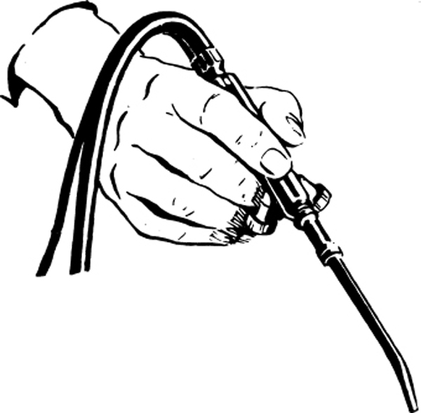
FIGURE 6-34 Holding the torch for welding light metal.
Figure 6-35 shows how the torch can be held for welding heavier work. In this method, the torch is held as one would hold a hammer; the fingers are curled underneath and the torch balanced easily in the hand so that there is no strain on the muscles of the hand. A good way to describe the grip of the torch is to say that it should be held like a bird, tightly enough so that it cannot get away but loosely enough so it will not be crushed.
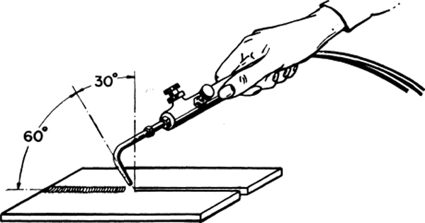
FIGURE 6-35 Holding the torch for welding heavy metal.
Forming the Puddle and Adding Filler Material
In the fusion welding process the base material (the materials to be joined) are brought to a molten state in the area of the joint, producing a puddle. The puddle is moved over the joint area, allowing the molten material from one part to intermingle with the other. To provide reinforcement to the joint, filler material is added by placing the filler rod in the puddle. The heat from the molten metal melts the filler material, and it too intermingles. Note that the filler material is melted by the puddle, not the torch flame. Melting the filler rod with the torch flame will generally result in the molten rod popping.
As the technician welds, it is important to note that the key to success in oxyacetylene welding is to control the motion of the puddle, making sure that the pattern used is consistent. The purpose of the rod is to add reinforcement material. Beginning welders have a tendency to chase the rod with the puddle instead of adding the rod to the puddle.
Another mistake frequently made by the novice welder is not adding enough rod. When all components of the welding process are properly balanced, the rod should remain in the puddle at all times. When chasing the rod, as just described, many novice welders add only one length of rod to the joint. This would be the equivalent to laying the rod along the joint and melting it as the bead is run along the joint. The welder should apply a light but constant pressure on the rod, so that more than one length of filler material is added to the joint.
Torch Motions
The welder may use either a semicircular, crescent, or a continuous circular motion, shown in Fig. 6-36. Regardless of the motion, the welder keeps the motion of the torch as uniform as possible in order to make smooth, even-spaced ripples. These ripples are the small, wavelike marks left on the surface of the completed weld by the action of the torch and welding rod.
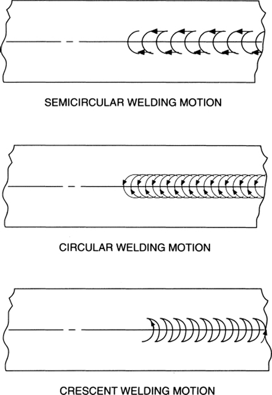
FIGURE 6-36 Acceptable welding motions.
Novice welders frequently find it difficult to concentrate on maintaining the torch motion and adding rod at the same time. For that reason it is recommended that the novice welder use a crescent motion. Since the preferred width of bead is three to five times the thickness of the base material, the novice welder may visualize the crown and bottom of the crescent motions as surrounding the filler rod, as shown in Fig. 6-37. Using this technique allows the novice welder to concentrate on the puddle pattern and apply pressure on the filler rod to add reinforcement.
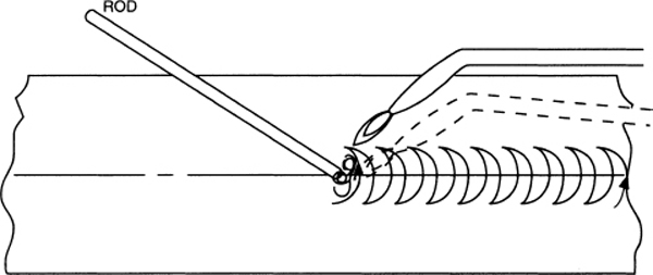
FIGURE 6-37 Crescent motion surrounds the filler rod.
Another difficulty experienced by novice welders is the control of heat to the part. The first approach to solving this difficulty is to soften the flame by reducing the pressure. Another way to solve the problem is to slightly increase the distance between the torch flame and the base material. A slight increase in distance has a significant effect upon the amount of heat absorbed by the part. Another option available to the welder, but not recommended to the novice, is to increase the rate of travel, or the speed with which the fusion process is accomplished.
Forehand Welding
Forehand welding, sometimes called forward welding, is a welding technique in which the torch flame is pointed forward in the direction the weld is progressing. In other words, it is pointed toward the unwelded portion of the joint, and the rod is fed in from the front of the torch or flame. Figure 6-38 shows how this is done. The welded portion of the weld joint is indicated by the crosshatched portion of the figure.

FIGURE 6-38 Forehand welding.
The torch head is tilted back from the flame to allow it to point in the direction that the weld is progressing. The angle at which the flame should contact the metal depends upon the type of joint, the position of the work, and the kind of metal being welded, but the usual angle is from 30° to 60°.
This forehand, or forward, technique must not be confused with the backhand, or backward, technique shown in Fig. 6-39 and explained in detail later in this chapter. The two techniques are distinctly different.
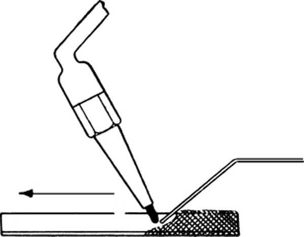
FIGURE 6-39 Backhand welding.
When forehand welding, filler rod is added to the pool of melting metal in front of the torch flame. The angle of the rod in relation to the torch must vary for different operations, but it is always necessary to add it to the weld by holding the end of the rod down into the molten pool of base metal formed by fusing the joint edges. If the rod is held above the pool and permitted to melt and drop into the weld, impurities floating on the surface of the molten metal will be trapped and a poor joint will be produced.
When the rod is used, it can be kept straight, or it can be bent to form a right angle near the end, as shown in Fig. 6-40.
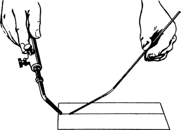
FIGURE 6-40 Welding rod bent to facilitate application.
The welding torch is brought down until the white cone of the flame is about  in [3.175 mm] from the surface of the base metal. The tip of the rod is then inserted in this puddle, and as the rod melts, the molten pool is gradually worked forward.
Backhand Welding
Backhand welding, sometimes called backward welding, is a technique in which the flame is directed back toward the finished weld, away from the direction the weld is progressing, and the rod is fed in from the back of the torch or flame. This is the method illustrated in Fig. 6-39, which shows that the torch flame is pointed toward the finished weld (the crosshatched part of the bar) at an angle of about 60° to the surface of the work.
The welding rod is added between the flame and the finished weld. The flame is moved back and forth across the seam with a semicircular motion, thus breaking down the edges and the side walls of the base metal in order to fuse them to the necessary depth. In this backhand technique, the semicircular motion is directed so that the base of the arc falls toward the finished weld.
Whether the forehand or the backhand technique is used, the end of the filler rod is always held in the pool and given a slight alternating, or back-and-forth rocking, movement as metal is added from the rod to the pool. This movement of the rod must not be made too energetically. It must be controlled so that the melted metal from the pool is not shoved over onto the metal, which is not yet hot enough to receive it.
The backhand technique is preferred by most welders for metals having a heavy cross section. The metal being welded may be held in any position except for welding seams that run vertically. By using the backhand technique, the large pool of melting metal that must be kept up at all times is more easily controlled, and the required depth of fusion in the base metal is easier to obtain.
Welding Positions
The four welding positions are flat-position welding, vertical-position welding, horizontal-position welding, and overhead-position welding. The welder must be able to make a good weld in any one of these four positions. A welding position refers to the plane (position) in which the work is placed for welding.
Two of the terms refer to welding the top or bottom surface of a work in a horizontal plane (flat work); overhead position is used when the underside of work is welded and flat position when the topside of work is welded. The other two terms refer to welding work in a vertical plane but make a distinction according to the direction of the line of weld. Thus horizontal position is used when the line runs across from side to side; vertical position when the line runs up and down. The line of weld is simply the path along which the weld is laid.
Figures 6-41 through 6-43 illustrate the four positions as seen from different viewpoints.

FIGURE 6-41 The four positions for welding.

FIGURE 6-42 Welding positions as viewed from the side.
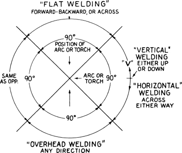
FIGURE 6-43 Torch direction for different welding positions.
Flat-Position Welding
The flat position is the position used when the work is laid flat or almost flat and welded on the topside, with the welding torch pointed downward toward the work. Thus, if a weld is made with the parts to be welded laid flat on the table or inclined at an angle less than 45°, it is designated as being flat. The weld may be made in this position by the forehand or by the backhand technique, depending upon the thickness of the metal. The seam runs horizontally.
Vertical-Position Welding
The vertical position is the position used when the line of the weld runs up and down (vertically) on a piece of work laid in a vertical or nearly vertical position. The welding torch is held in a horizontal or almost horizontal position. Thus, when the parts are inclined at an angle of more than 45°, with the weld running vertically, it is described as a vertical weld. The weld should be made from the bottom, with the flame pointed upward at an angle of from 45° to 60° to the seam for welding in this position. The rod is added to the weld in front of the flame, as it is in ordinary forehand welding. Figure 6-44 shows how the filler rod is added to the weld in front of the flame while making a weld in the vertical position.
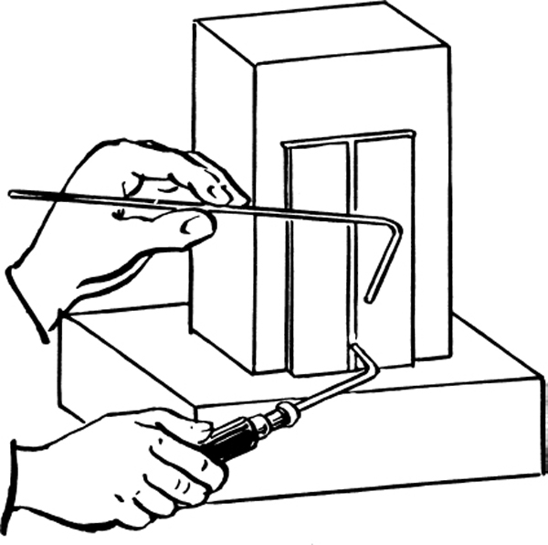
FIGURE 6-44 Adding rod when making a vertical weld.
Horizontal-Position Welding
The horizontal position is the position used when the line of weld runs across (horizontally) on a piece of work placed in a vertical or almost vertical position; the welding torch is held in a horizontal or almost horizontal position. Thus, when a weld is made with the parts in a vertical position or inclined at an angle of more than 45° with the seam running horizontally, it is called a horizontal weld. The seams in this horizontal position may be welded by either the forehand or the backhand technique; in either case, the flame should point slightly upward in order to aid in keeping the melting metal from running to the lower side of the seam. The welding rod should be added to the weld at the upper edge of the zone of fusion, since it dissipates some of the heat and lowers the temperature enough to help in holding the melting metal in the proper place. Figure 6-45 shows the hands of the welder holding the torch and the rod in this position.

FIGURE 6-45 Positions of hand and torch for a horizontal weld.
Overhead-Position Welding
The overhead position is the position used when work is flat (horizontal) or almost flat and is welded on the lower side, with the welding torch pointed in an upward direction toward the work. Thus when a weld is made on the underside of the work with the seam running horizontally, or in a plane that requires a flame to point upward from below, it is described as an overhead weld.
Either the forehand or the backhand technique can be used in welding seams in an overhead position. In either case, the flame must be pointed upward and held at about the same angle as it is for welding in a flat position. The volume of flame used for overhead welding should not be permitted to exceed that required to obtain a good fusion of the base metal with the filler rod. Unless the welder avoids creating a large pool of melting metal, the metal will drip or run out of the joint, thus spoiling the weld. Figure 6-46 shows a welder’s hands holding the rod and torch correctly for this type of weld.
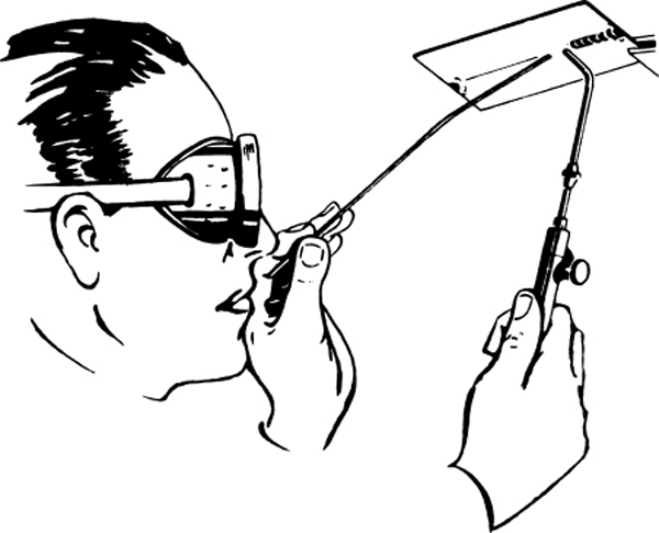
FIGURE 6-46 Positions of hand and torch for an overhead weld.
Weld Quality
The properly completed weld should have the following characteristics:
1. The seam should be smooth and of a uniform thickness.
2. The weld should be built up to provide extra thickness at the seam.
3. The weld metal should taper off smoothly into the base metal.
4. No oxide should be formed on the base metal at a distance of more than in [12.7 mm] from the weld.
5. The weld should show no signs of blowholes, porosity, or projecting globules.
6. The base metal should show no sign of pitting, burning, cracking, or distortion.
Reducing Distortion and Residual Stress
To reduce distortion and residual stress produced by welding, the expansion and contraction of the metal should be controlled. The distortion is especially noticeable in welding long sections of thin sheet metal because the thinner the metal being welded, the greater the distortion.
Four things a welder can do to control the action of those forces that adversely affect the finished weld are the following: (1) distribute the heat more evenly; (2) put a smaller amount of heat into the weld; (3) use special fixtures to hold the metal rigidly in place while it is being welded; and (4) provide a space between the edges of the joint. The nature of each welding job determines whether only one or all four of these methods should be used.
In discussing expansion and contraction, the even distribution of heat was explained. Preheating the entire metal object before welding sets free the stored-up forces and permits a more uniform contraction when the welding job is completed.
Putting a smaller amount of heat into a weld is difficult for a beginner, although an experienced welder can estimate accurately the amount of heat required. This is an example of the skill that comes from experience. One of the “tricks of the trade” is to use a method called stagger welding, shown in Fig. 6-47. The operator welds briefly at the beginning of the seam, skips to the center, then jumps to the end, comes back to where the first weld ended, and repeats this staggered process until the weld is finished.
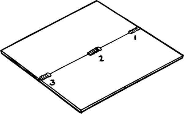
FIGURE 6-47 Stagger, or skip, welding.
Another term for stagger welding is skip welding, which is defined as a welding technique in which alternate intervals are skipped in the welding of a joint on the first pass and completed on the second pass or successive passes. The purpose is to prevent any one area of the metal from absorbing a great deal of heat, thus avoiding buckling and the tendency toward cracking.
When a welder uses special fixtures to hold the metal rigidly in place while it is being welded, excessive movements of the metal are hindered and the severe distortion resulting from expansion and contraction is prevented. A fixture is a rigid structure or mechanism, either wood or metal, that holds parts while they are being worked on (drilled, sawed, welded, etc.) before assembly, or that holds the component parts while they are being assembled or disassembled. Therefore, a welding fixture is simply a contrivance that holds the metal sections rigidly in place while a seam is welded. Fixtures are fastened tightly, but not so tightly that they will hinder the normal expansion and contraction of the metal at the ends of the joints. If a fixture is fastened too tightly, it causes internal stresses in the metal that lower its ability to carry heavy loads.
The fourth method for reducing distortion and residual stresses is the careful spacing of the pieces to be welded. Figure 6-48 shows how a tapering space is allowed between the pieces that are to be welded together. This tapering space is a distance equal to the thickness of the metal for every foot of seam length. For example, if a welder is to make a joint between two pieces of metal that are both in [12.7 mm] thick and 1 ft [30.45 cm] long, the space between them should be in [12.7 mm] at the ends opposite the starting point. If these same two pieces were 2 ft [60.96 cm] long, then the space at the wider ends would be twice as much, or 1 in [2.54 cm].

FIGURE 6-48 Tapering space to allow for metal expansion.
Figure 6-49 shows a method of providing for expansion of the base material when welding butt joints. The edges are set parallel and tack-welded. A tack weld is one of a series of small welds laid at intervals along a joint to hold the parts in position while they are being welded. This method is used for making short, straight seams or the curved seams on tubing, cylinders, tanks, etc.
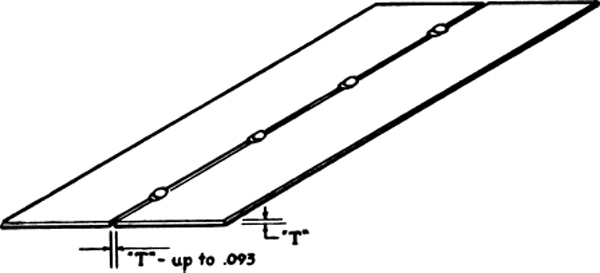
FIGURE 6-49 Tack welding to hold metal in position.
Figure 6-50 shows how the edges for butt joints may be set and spaced when tack welding is not used; the amount of spacing depends on the kind of metal being welded and usually ranges from  to in [3.18 to 9.53 mm] for each foot [30.48 cm] of the seam length. This method is better for flat sheets and longitudinal seams of cylindrical shapes.
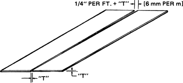
FIGURE 6-50 Spacing of metal parts for welding.
Figure 6-51 shows a welding fixture for sheet-metal butt joints. It is useful for both flat sheets and longitudinal seams of cylindrical shapes.

FIGURE 6-51 A welding fixture for sheet-metal butt joints.
Figure 6-52 shows a fixture consisting of four pieces of angle iron, which is used for welding butt joints in sheet metal. The angles for supporting the work on the lower side may be bolted or welded together. A recess of  to
to  in [0.794 to 1.191 mm] deep and from to
  in [12.7 to 19.05 mm] wide is machined in the center. This is labeled “milled groove” in the illustration.
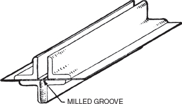
FIGURE 6-52 Use of a welding fixture.
The fixture shown in Fig. 6-53 is used for welding corner joints. It consists of three pieces of angle iron. The edge of the piece used to support the work on the lower side is ground or machined off to provide about -in [1.59-mm] clearance for the joint. This enables the fusion to penetrate the base metal all the way through at this point. These fixtures are held in place on the metal by means of C-clamps.

FIGURE 6-53 Welding fixture for corner joints.
In welding plate stock where the shape of the part permits, the butt joints may be set up as illustrated in Fig. 6-50, but if the shape of the work is such that the joint edges must be parallel, either the skip-welding procedure previously explained or the step-back method should be used for welding the joint. Either of these methods will lower the heat strains, because the heat is more evenly distributed over the whole length of the seam, thus causing the expansion and contraction to be uniform.
The step-back method, also called the back-step method, is a welding technique in which the welder welds and skips intervals between tack welds with each successive pass until the joint is completely welded. As each pass is completed, the welding is “back-stepped” or “stepped-back” to the next unwelded interval near the beginning of the weld. Figure 6-54 illustrates the step-back method. This should be studied and compared with the stagger welding shown in Fig. 6-47 and a more detailed drawing of this same “skip” method shown in Fig. 6-55.
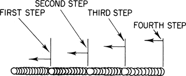
FIGURE 6-54 The step-back method of welding.

FIGURE 6-55 Details of skip welding.
Figure 6-56 shows that when it is not possible to design a fixture for the work and the metal is held in such a manner that normal expansion and contraction are restrained, the edges of the sheet may be bent up at the joint, as shown in the upper drawing, or a bead may be formed in each sheet parallel to the seam,  to 1 in [1.59 to 2.54 cm] from the joint, as shown in the lower drawing of Fig. 6-56. Normally, either of these forms will straighten sufficiently on cooling to relieve the strain of the weld. However, if for any reason bends of this type are not practical, the welder may place chill plates or a cold pack of wet nonflammable material on the metal near the joint and parallel to the seam to reduce the flow of heat and the expansion that follows.

FIGURE 6-56 Use of bend or bead to restrain distortion.
Figure 6-57 shows the welding procedure for reducing stresses in tee joints. The welding in this case alternates from one side of the vertical member to the other. If the plate is heavy, the tee joints are heated to a dull red on the opposite side from the side on which the weld is being made. A separate torch is used for this purpose. If done carefully, this heating causes a uniform expansion on both sides of the plate and produces an even contraction that prevents the parts from being pulled out of their correct alignment.

FIGURE 6-57 Reducing stresses in welding a tee joint.
There are several methods for providing for the expansion in the welding of castings. The one selected in each case depends upon the type, kind, and shape of the casting and also on the nature of the break being welded. The welder who has mastered the principles and techniques already described should have no trouble in selecting the correct procedure for each job. For example, the entire casting might require preheating to a temperature that will prevent expansion strains on one job, whereas on another job it might be enough to apply local preheating—that is, heat applied only in the vicinity of the welding zone.
When preheating is applied, the parts preheated must be cooled evenly and slowly. Depending upon the design and other factors, the opposing parts or sections may be preheated to relieve the strains that come from welding. Mechanical devices such as screw jacks may be used as an additional precautionary measure. Figure 6-58 shows the application of methods of providing expansion in the welding of rectangular castings, and Fig. 6-59 shows the method of providing for expansion in the welding of circular castings.
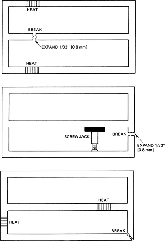
FIGURE 6-58 Providing for expansion in welding rectangular castings.
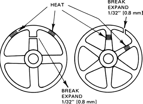
FIGURE 6-59 Providing for expansion in welding circular castings.
When parts are fabricated or repaired by welding, there is usually some stress that remains. This stress should be relieved to obtain the full strength of the weld and the base metal. Heat treatment, which is discussed in considerable detail in Aircraft Basic Science, is the most reliable method of relieving stress, provided that the part can be heated in a furnace to the stress-relieving temperatures and then cooled slowly and evenly. For example, aluminum and aluminum alloys require a temperature of from 700 to 800°F [371 to 427°C]; gray cast iron, 900 to 1000°F [482 to 538°C]; nickel-chromium-iron alloy (Inconel), 1400°F [760°C]; carbon steels up to 0.45 percent carbon, 1000 to 1200°F [538 to 649°C]; chrome-molybdenum-alloy steel, 1150 to 1200°F [621 to 649°C]; and chrome-nickel stainless steel (18-8), from 1150 to 1200°F [621 to 649°C].
Local heating with a welding flame may be used to relieve or eliminate distortion in structures fabricated of steel tubing, angle iron, and similar materials by bringing the metal to a red heat at the proper locations. Figure 6-60 shows a tube pulled out of alignment by weld shrinkage being given this treatment, and Fig. 6-61 shows an angle iron pulled out of alignment by weld shrinkage being given a similar application of local heat.
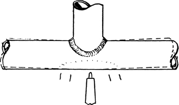
FIGURE 6-60 Application of heat to straighten a tube.

FIGURE 6-61 Use of heat to straighten an angle section.
Practices to Avoid
• Welds should not be filed to present a smooth appearance. Filing will usually weaken the weld.
• Welds must not be filled with solder, brazing metal, or any other filler.
• When it is necessary to reweld a joint, all the old weld metal must be removed before proceeding with the new weld.
• A new weld should never be made over an old weld if it can be avoided. The heat of rewelding increases the brittleness of the weld material and causes it to lose strength.
• A weld should never be made over a joint that was previously brazed. Brazing metal (brazing filler rod) penetrates and weakens the steel.
Simple Tests for Welds
There are many reliable tests for welds, but at this stage of training, the technician should at least be able to apply one or two very simple tests to judge progress. One of these is usually called the bend test. The welder allows the metal to cool slowly and then picks it up with a pair of pliers and clamps the metal in a vise with the weld parallel to the top of the jaws of the vise and slightly above the top of the vise, as shown in Fig. 6-62. The welder strikes the top of the metal with a hammer so that the metal is bent along the line of the weld. The weld should be bent in on itself—that is, bent so the bottom of the weld is in tension and the top is in compression. If the weld breaks off very sharply and shows a dull, dirty break and the presence of blowholes, the weld is unsatisfactory. If the weld has been made properly, the metal will not break off short. Instead, it will be distorted under the blows of the hammer until it forms an angle of at least 90° without cracking under repeated hammering.

FIGURE 6-62 Bend test for a weld.
A visual inspection is another simple test. The welder examines the smoothness of the bead, the amount of reinforcement (making certain that the seam is at least 25 to 50 percent thicker than the base metal), and the cleanliness of the completed weld. The contour should be even. It should extend in a straight line, and its width and height should be consistent. No pits should be present. It should be understood that a clean, smooth, fine-appearing weld is not necessarily a good weld, because it may be dangerously weak inside. However, the opposite is true; that is, if the weld is rough-pitted, uneven, and dirty looking, the weld is almost always unsatisfactory inside.
Gas Welding Aluminum, Magnesium, and Titanium
It is strongly recommended that the appropriate type of inert-gas welding be employed when aluminum, magnesium, or titanium parts must be joined by welding. These metals and their alloys oxidize very rapidly when heated, and it is difficult to protect the surfaces from oxidation in gas welding even though flux is applied liberally.
When magnesium reaches a sufficiently high temperature, it burns with a very bright flame. Care must, therefore, be taken to avoid a situation where magnesium shavings, particles, or scraps can be ignited. Titanium, in the molten state, reacts rapidly with oxides and oxygen. When being welded, it must be completely protected from oxygen.
Pure aluminum and some of its alloys can be gas welded. Designations for weldable aluminum and alloys are 1100, 3003, 4043, and 5052. Alloys 6053, 6061, and 6151 can be welded if provision is made for heat treating after welding.
Aluminum should be welded with a soft neutral flame or a slightly reducing flame when either acetylene or hydrogen is used for the welding gas. This ensures that there will be no oxygen in the flame to combine with the aluminum.
Before starting to weld aluminum, the edges to be welded must be thoroughly cleaned. Solvents can be used to remove grease, oils, or paint. The solvent must be such that it evaporates completely dry and leaves no residue. Oxides can be removed from the areas to be welded with fine emery paper. Care must be taken not to scratch the aluminum outside the weld areas because this will cause corrosion.
The preparation of the edges of aluminum sheet or plate that are to be gas welded depends upon the thickness of the material. For thicknesses of 0.060 in [1.52 mm] or less, a 90° flange can be formed on the edges. The height of the flange should be about the same as the thickness of the metal. A cross-section drawing of flange edges is shown in Fig. 6-63(a). If the metal is between 0.060 and 0.190 in [1.52 and 4.83 mm], the penetration of the weld is improved by notching the metal, as shown in Fig. 6-63(b). This practice also aids in preventing distortion of the metal due to expansion. If the metal thickness is greater than 0.190 in [4.83 mm], it should be beveled and notched, as shown in Fig. 6-63(c).

FIGURE 6-63 Edge preparation for gas welding aluminum sheet and plate.
When the metal edges have been cleaned and prepared as explained, aluminum welding flux should be applied. If possible, the flux should be brushed on both the flame side and the opposite side of the metal. The welding rod should also be dipped in the flux. After completion of the weld, the flux should be removed completely by washing. If flux remains, it will cause corrosion.
As mentioned previously, the flame used for aluminum welding should be soft (mild). This type of flame is produced by adjusting the torch as low as possible without causing the tip to pop. The flame is applied to the edges of the work at an angle of approximately 45° until the aluminum begins to melt. It is difficult to tell when the aluminum has reached melting temperature because its appearance does not change appreciably. Touching the tip of the welding rod to the heated area will reveal when the aluminum is beginning to soften. If the aluminum becomes too hot, it will drop away and form a hole in the material. If the flame is too harsh, this condition will be aggravated. In any case, only an experienced welder should attempt to perform this type of work.
If possible, the material to be welded should be supported in a fixture, which will reduce distortion as much as possible. The material should be preheated before starting the weld by passing the torch over the entire area surrounding the weld. Care must be taken not to overheat the material, because doing so will change the structure of the metal and reduce its strength.
The welding of magnesium with butt joints is accomplished in a manner similar to the welding of aluminum. (The butt weld is generally the only type of weld made with magnesium when using oxyacetylene equipment.) The edges to be welded should be cleaned and the oxides removed. Solvents are used to remove oil or grease, and fine emery cloth or paper can be used to remove the oxides.
Edge preparation of sheet magnesium differs from that of aluminum because magnesium alloys cannot be bent sharply without cracking. For sheet magnesium alloy with thickness of 0.040 in [1.016 mm] or less, the edges should be bent up in a curve, as shown in Fig. 6-64(a). For sheet thicknesses from 0.040 to 0.125 in [1.02 to 3.18 mm], the edges of the metal are left square with a space of 0.0625 in [1.59 mm] between the edges of the sheets to be welded; see Fig. 6-64(b). For magnesium plate with thicknesses between 0.125 and 0.250 in [3.18 and 6.35 mm], the edges should be beveled as shown in Fig. 6-64(c). The bevel on each edge is approximately 45°, making an included angle of 90°. A space is allowed between the sheets as shown. For magnesium plate more than 0.250 in [6.35 mm] in thickness, the edges are beveled as for the thinner plate; however, the space between the edges is increased to 0.125 in [3.18 mm].
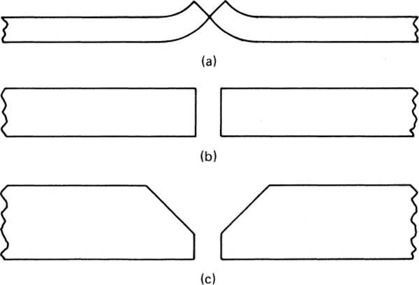
FIGURE 6-64 Edge preparation for gas welding magnesium sheet and plate.
The welding rod used with magnesium alloys must be of the same alloy as the material being welded and should be available from the manufacturer of the alloy. A protective coating is applied to the magnesium alloy welding rod to protect it from corrosion. This coating must be removed before the rod is used in welding.
The experienced welder will usually develop the most satisfactory techniques for welding magnesium based on experience. The weld may be made in much the same way as for aluminum, or the tip of the welding rod may be kept in the center of the molten pool as the weld continues. It is recommended that the weld be made in one continuous pass unless oxidation takes place. In this case, the welding must be stopped and all the oxide removed before continuing.
To prevent distortion, the edges of the joint should be tack-welded at intervals of 0.5 to 3 in [12.7 to 76.2 mm], depending upon the shape and thickness of the metal. Distortion that does occur can be straightened with a soft face mallet while the metal is still hot.
Completed welds should be allowed to cool slowly to the level where the material can be handled. Then the weld should be scrubbed clean with a stiff brush and water to remove the flux. After this the part should be soaked in hot water to dissolve and remove any traces of flux not removed by brushing. After soaking, the part should be treated by immersion in an approved acid bath to neutralize alkalinity and then rinsed in fresh water and dried as quickly as possible. Clean, bare magnesium will corrode rapidly unless given a treatment to provide a corrosion-resistant chemical coating. One such treatment is accomplished with an approved chromic-acid solution. Another treatment that is suitable for many magnesium alloys is the dichromate treatment. This involves boiling the magnesium in a solution of sodium dichromate after an acid pickle bath. This treatment is effective for corrosion prevention and provides a good base for primers and finishes. It can be used for all magnesium alloys except those containing thorium.
ELECTRIC-ARC WELDING
Electric-arc welding, also referred to as stick-electrode welding and technically referred to as shielded metal arc welding (SMAW), is used here to denote the standard arc process, which utilizes an electrode filler rod and is generally employed for welding heavy steel. This method requires a special generator to provide a low-voltage, high-amperage current for the arc. The power supply may be an electric motor-driven generator, an engine-driven generator, or a special transformer.
The electric arc is made between the tip end of a small metal wire, called the electrode, which is clamped in a holder held in the hand, and the metal being welded. A gap is made in the welding circuit by holding the tip of the electrode to in [1.59 to 3.18 mm] away from the work. The electric current jumps the gap and makes an arc, which is held and moved along the joint to be welded. The heat of the arc melts the metal. The arc is first caused (“struck”) by touching the electrode to the metal, and then the electrode is withdrawn slightly to establish the correct gap across which the arc flows.
The several types of welding machines include motor generators, engine-driven generators, transformers, rectifiers, and combination transformers and rectifiers. Figure 6-65 illustrates a typical arc-welding power supply. Each type has its place and purpose, but the basic function of each is the same—that is, to provide a source of controlled electric power for welding. This controlled electric power has the characteristic of high amperage at low voltage. The high amperage is required to provide sufficient heat at the arc to melt the metal being welded. The voltage must be low enough to be safe for handling and yet high enough to maintain the arc. The welding machine permits the operator to control the amount of current used. This, in turn, controls the amount of heat at the arc. Some welding machines permit the operator to select either a forceful or soft arc and to control its characteristics to suit the job.
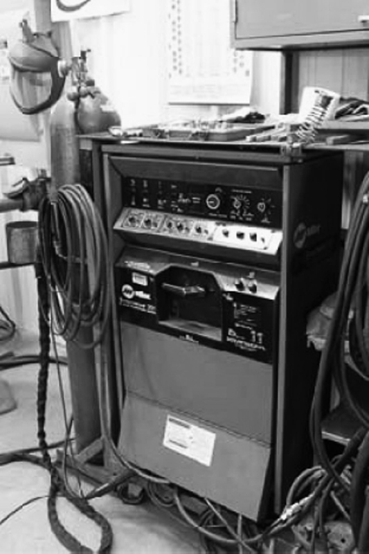
FIGURE 6-65 Power supply unit for arc welding. (Lincoln Electric Company.)
Good welders do more than simply hold the arc. They must, first of all, be able to select the correct size and type of electrode for each job. They must know which machine to use for the job and be able to set the current and voltage controls properly. They must be able to manipulate the electrode and arc to make a satisfactory weld under varying conditions. In addition, welders must have a knowledge of joint preparation, positioning the work, distortion, and many other factors that enter into the final result of a good weld. They must be skilled in both the mechanics and craft of welding. Nearly anyone can “stick two pieces of metal together,” but becoming a good welder requires study, training, and practice.
The Welding Circuit
The operator’s knowledge of arc welding must go beyond the arc itself to include how to control the arc, and this requires a knowledge of the welding circuit and the equipment that provides the electric current used in the arc. Figure 6-66 is a diagram of the welding circuit. The external circuit begins where the electrode cable is attached to the welding machine and ends where the ground cable is attached to the welding machine. When direct-current, straight-polarity power is used, the current flows through the electrode cable to the electrode holder, through the holder to the electrode, and across the arc. From the work side of the arc, the current flows through the base metal to the ground cable and back to the welding machine. The circuit must be complete for the current to flow, which means that it is impossible to weld if the cables are not connected to the machine or to either the electrode or the work. All connections must be firm so the current can flow easily through the entire circuit.
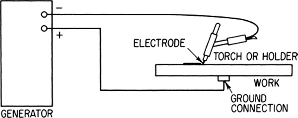
FIGURE 6-66 An arc welding circuit.
Welding Arc
The action that takes place in the arc during the welding process is illustrated in Fig. 6-67. The arc stream, seen in the middle of the picture, is the electric arc created by the current flowing through air between the end of the electrode, technically known as the anode, and the work, more properly referred to as the cathode. As the current flows through the arc stream, a column of ionized gas called the plasma is formed. The arc is very bright as well as hot and cannot be looked at with the naked eye without risking painful, though temporary, injury. It is, therefore, essential that the operator wear a suitable protective hood, such as the one shown in Fig. 6-68. New style helmets have an auto-darkening feature that allows the welder to see the welding torch and filler rod so that he/she can position them in the correct position. As soon as the intense light of the welding starts the helmet lens will automatically darken. The darkness of the lens is adjustable. Welding goggles used for gas welding will not adequately protect the eyes of the welder during TIG or MIG welding processes.
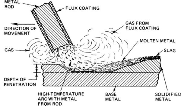
FIGURE 6-67 The action in a welding arc.

FIGURE 6-68 A welding helmet. (Linde Div., Union Carbide Corp.)
The plasma is a combination of both neutral and excited gas atoms. In its center are electrons, atoms, and ions. The heat of the arc is caused by the collision of these particles at the accelerated speeds caused by voltage drop as they move between the anode and cathode. The temperature of this arc is from 6000 to 11 000°F [3315° to 6090°C], which is more than enough to melt the metal. The temperature is most affected by three factors: the type and amount of electrical power, the distance between the anode and cathode (the gap between the electrode and the work piece), and the type of atmosphere or gases between the anode and cathode.
The arc melts the plate, or base, metal and actually digs into it, just as the water flowing through a nozzle on a garden hose digs into the earth. The molten metal forms a pool, or “crater,” and tends to flow away from the arc. As it moves away from the arc, it cools and solidifies. A slag forms on top of the weld to protect it during cooling. The slag comes from the flux coating on the electrode.
Arcs for welding are produced by different kinds of power supplies and the various types of power produce arcs with different characteristics. The power supply may be designated dcsp, dcrp, or ac. Here dcsp means direct current, straight polarity. Straight polarity is the condition when the electrode is negative and the base metal or work is positive. Also, dcrp means direct current, reverse polarity, where the electrode is positive. The direction of current will have a pronounced effect on the depth and penetration of the weld.
Ac power, of course, means alternating current. With ac power, the order in which the leads from the power source are connected will make no difference. Ac power is often considered the most efficient of the power sources because it produces a higher temperature for a given amperage.
Dcsp power provides the deepest penetration for a given amperage and is used when welding rusty surfaces and tight-fit joints. The technician should be aware that this process develops the most heat.
Dcrp power produces the smoothest bead and less splatter due to the lessened penetration. Thinner materials and joints with wide gaps are most frequently welded with dcrp power.
Electrode, or Rod
In preparing to perform arc welding, the operator should seek to determine the best power source and type of welding rod for the welding being done. Very often, however, only one source of power is available, and the only choices the operator has are the direction of welding current and type of rod.
The function of the electrode is much more than simply to carry current to the arc. The electrode is composed of a core of metal rod or wire material, around which a chemical coating has been extruded and baked. The core material melts in the arc, and tiny droplets of molten metal shoot across the arc into the pool. The electrode provides filler metal for the joint to occupy the space or gap between the two pieces of the base metal. The coating also melts or burns in the arc and serves several functions. It makes the arc steadier, increases the arc force, provides a shield of smokelike gas around the arc to keep oxygen and nitrogen in the air away from the molten metal, and provides a flux for the molten pool, which picks up impurities and forms the protective slag. The electrodes to be used in any arc-welding operation depend upon the material being welded, the type of power being used, and the type of weld. The operator must make certain that the rod chosen will supply the strength required of the weld.
The American Welding Society (AWS) has established a standard classification system for the coding of SMAW. The coding classifies electrodes by the electrode’s tensile strength, best welding position, and flux-welding current recommendations. Since most SMAW is related to the welding of mild steel, only the code as commonly associated with mild steel-core electrodes is identified here. If any other materials are to be considered, the electrode manufacturer’s catalogs should be consulted for the proper electrode selection.
The AWS code for mild steel electrodes is a five- or-six-position identifier, which begins with a letter. The letter designates the core material. E indicates a mild steel.
The next two or three positions are numbers that identify the tensile strength of the core material. The fourth position is used for tensile strength identification only if the code is six positions in length.
The next-to-last position (fourth in a five-position code or fifth in a six-position code) indicates the recommended welding position. 1 indicates any position. 2 indicates the code composition is suitable for horizontal fillets and flat-position welding.
The last position in the code signifies the type of flux coating and recommended power source. Table 6-3 shows the meanings of the numbers in the last position of the code.
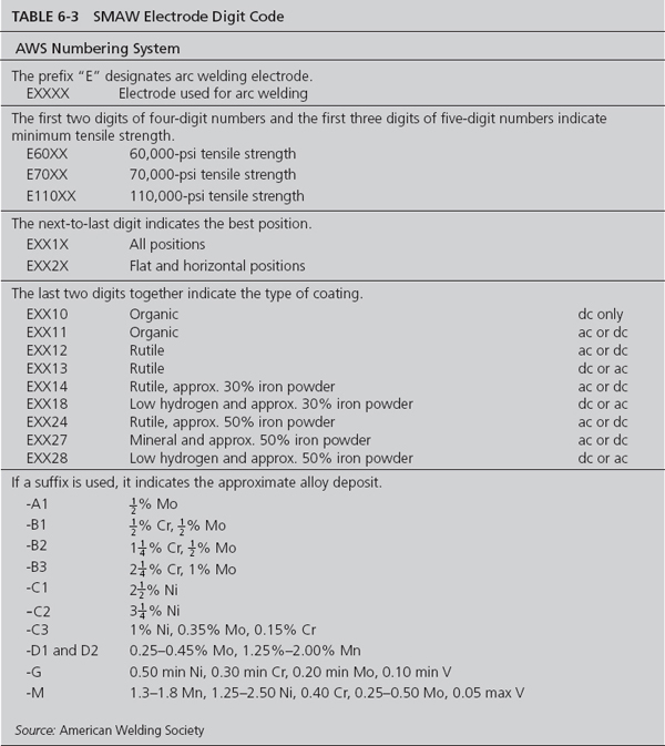
Table 6-4 shows a series of recommended SMAW electrodes for a variety of usages. Note also that Table 6-4 denotes the electrode’s diameter and amperage range. The selection of the amperage is proportional to the diameter of the electrode. The greater the diameter of the electrode, the greater the amperage required. Although the best amperage for any particular application will require fine tuning for a variety of variables, a good rule of thumb is to start with an amperage equal to the decimal equivalent of electrode diameter, expressed in inches, multiplied by 1000. For example, a good starting amperage for a -in-diameter electrode is 125 A.
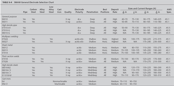
Once the arc is struck, the welder needs to maintain a gap between the material and the electrode of slightly less than the diameter of the electrode. Since the electrode is constantly shortening in length, a particular height is difficult to judge and maintain by sight. Experienced SMAW welders maintain the proper distance by sound and observations of the finished weld. A sharp crackling sound, similar to an egg frying, is an indication that the proper arc gap is being maintained. Electrode sticking to the material during the welding process is an obvious result of an arc gap that is too short. Excessive splattering and poor bead quality indicate an arc gap that is too large.
Once the arc is struck and the gap is established, the welder will use bead patterns similar to those used in gas welding. Whatever the pattern used, it should be consistently maintained during the SMAW process.
Self-shielded flux-cored electrode welding is an application of shielded metal arc welding in a semiautomated application. The primary differences between self-shielded flux-cored electrode welding and SMAW is that the electrode comes in the form of a wire rather than a rod and the flux is located in the center of a tubular electrode wire rather than external to it. Since self-shielded flux-cored electrode welding does not lend itself readily to aircraft-maintenance applications, further discussion in this text is limited to similarities to other welding processes.
INERT-GAS WELDING
The term inert-gas welding describes an electric-arc welding process in which an inert gas is used to shield the arc and molten metal to prevent oxidation and burning. The process originally employed helium for the gas shield, and the name Heliarc was given the process by the Linde Division of the Union Carbide Corporation. Many improvements have been made in the original process and techniques, and new names have been assigned.
Types of Inert-Gas Welding
Tungsten Inert-Gas (TIG) Welding
Tungsten inert-gas (TIG) welding, classified as gas tungsten-arc welding (GTAW) by the AWS, is accomplished by means of a torch with a nonconsumable tungsten electrode. The electrode is used to sustain the arc and the molten pool of metal. Filler rod is added to the pool to develop the desired thickness of bead. Inert gas, usually argon, is fed to the weld area through the gas cup on the torch. The gas cup surrounds the electrode and directs the gas in a pattern to prevent the intrusion of oxygen and nitrogen from the air. In some cases it has been found beneficial to mix small amounts of oxygen and other gases with the inert gas to gain the best results.
Metal Inert-Gas (MIG) Welding
Another type of inert-gas welding utilizes a metal electrode, which melts and is carried into the weld pool to provide the extra thickness desired. This type of weld has been called metal inert-gas (MIG) welding and is classified gas metal-arc welding (GMAW) by the AWS. In this type of welding, the metal electrode must be of the same material as the base metal being welded. Since the electrode is consumed in this process, the electrode wire is automatically fed through the torch so that the torch is held a constant distance from the work surface. Carbon dioxide added to argon gas is commonly used for the MIG process.
Plasma-Arc Welding
Plasma-arc welding (PAW) is the third type of inert-gas welding that is discussed in any detail in this chapter. Plasma-arc welding is often used in applications where GTAW is preferred but more heat or speed is required, such as the welding of exotic metals. In plasma-arc welding the flow of the plasma is restricted but is at an increased speed through an orifice, resulting in higher temperatures and improved concentration of heat.
Advantages of Inert-Gas Welding
Inert-gas welds, because of 100 percent protection from the atmosphere, are stronger, more ductile, and more corrosion-resistant than welds made with ordinary metal-arc processes. In addition, the fact that no flux is required makes welding applicable to a wider variety of joint types. Corrosion due to flux entrapment cannot occur, and expensive post-welding cleaning operations are eliminated. The entire welding action takes place without spatter, sparks, or fumes. Fusion welds can be made in nearly all metals used industrially. These include aluminum alloys, stainless steels, magnesium alloys, titanium, and numerous other metals and alloys. The inert-gas process is also widely used for welding various combinations of dissimilar metals, and for applying hard-facing and surfacing materials to steel.
Inert-Gas Welding Joint Design
Many of the preparation and welding techniques are the same or similar for inert-gas welding as for oxyacetylene welding. This section introduces the methods and procedures that are different for inert-gas welding when compared to oxyacetylene welding operations.
Although there are innumerable welding joint designs possible, the basic types are butt joint, lap joint, corner joint, edge joint, and tee joint. Almost any TIG, MIG, or plasma-arc weld will be one or a combination of two or more of these basic types. Selection of the proper design for a particular application depends primarily on the following factors:
1. Physical properties desired in the weld
2. Cost of preparing the joint and making the weld
3. Type of metal being welded
4. Size, shape, and appearance of the part to be welded
Filler metal in the form of welding rod need not be used if proper reinforcement and complete fusion of the edges can be obtained without it. The joint designs described in this section are but a few of the many that can be successfully welded with the inert-gas method.
No matter what type of joint is used, proper cleaning of the work prior to welding is essential if welds of good appearance and physical properties are to be obtained. On small assemblies, manual cleaning with a wire brush, steel wool, or a chemical solvent is usually sufficient. For large assemblies or for cleaning on a production basis, vapor de-greasing or tank cleaning may be more economical. In any case, it is necessary to remove completely all oxide, scale, oil, grease, dirt, rust, and other foreign matter from the work surfaces.
Precautions should be taken when using certain chemical solvents such as carbon tetrachloride, trichlorethylene, and tetrachloroethylene, which break down in the heat of an electric arc and form a toxic gas. Welding should not be done when these gases are present, and the solvents should not be exposed to the heat of the welding torch. Inhalation of the fumes can be dangerous; hence proper ventilation equipment should be provided to remove fumes and vapors from the work area.
The square-edge butt joint shown in Fig. 6-69 is the easiest to prepare, and it can be welded with or without filler material, depending on the thickness of the pieces being welded. Joint fit for a square-edge butt joint should always be true enough to assure 100 percent penetration with good fusion. When welding light-gauge material without adding filler metal, extreme care should be taken to avoid low spots and burn-through. The heavier thickness generally requires filler metal to provide adequate reinforcement.
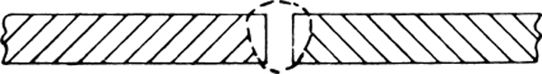
FIGURE 6-69 Square-edge butt joint.
The single-V butt joint, shown in Fig. 6-70, is used where complete penetration is required on material thicknesses ranging between and 1 in [9.5 and 25.4 mm]. Filler rod must be used to fill in the V. The included angle of the V should be approximately 60°; the root face will measure from to in [3.18 to 6.35 mm], depending on the composition and thickness of the pieces being welded.
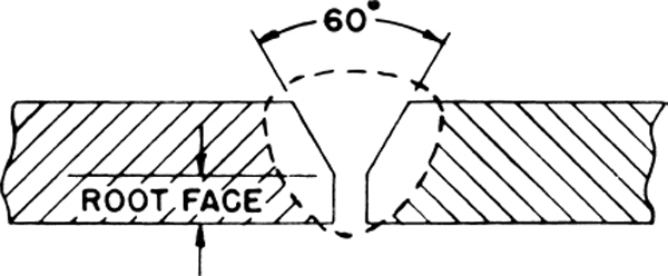
FIGURE 6-70 Single-V butt joint.
The double-V butt joint of Fig. 6-71 is generally used on stock thicker than in [12.7 mm], where the design of the assembly being welded permits access to the back of the joint for a second pass. With this type of joint, proper welding techniques assure a sound weld with 100 percent fusion.

FIGURE 6-71 Double-V butt joint.
A flange-type butt joint such as that illustrated in Fig. 6-72 should be used in place of the square-edge butt joint where some reinforcement is desired. This joint is practical only on relatively thin material, about 0.065 to 0.085 in [1.65 to 2.16 mm].

FIGURE 6-72 Flange joint.
A lap joint has the advantage of eliminating entirely the necessity for edge preparation. Fig. 6-73 (p. 154) shows such a joint. The only requirement for making a good lap weld is that the plates be in close contact along the entire length of the joint and that the work be thoroughly cleaned, as explained previously. On material in [6.35 mm] thick or less, lap joints can be made with or without filler rod. When no filler metal is used, care must be taken to avoid low spots or burn-through. The laptype joint is not usually recommended on material thicker than in [6.35 mm] except for rough fit-up. When so used, filler rod must always be added to ensure good fusion and buildup. The number of passes required depends on the thickness of the pieces being joined.
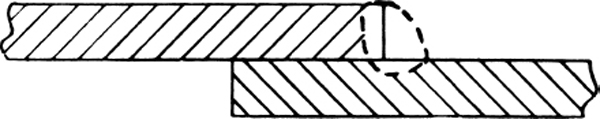
FIGURE 6-73 Lap joint.
Corner joints are frequently used in the fabrication of pans, boxes, and all types of containers as well as for other heavier purposes. The type A corner joint, shown in Fig. 6-74, is used on material thicknesses up to in [3.18 mm]. No filler metal is required, as the amount of base metal fused is sufficient to ensure a sound, high-strength weld. Type B, as shown in the illustration, is used on heavier material that requires filler rod to provide adequate reinforcement. Type C is used on very heavy material, where 100 percent penetration is impossible without the beveled-edge preparation. The nose should be thick enough to prevent burn-through on the first pass. The number of passes required depends on the size of the V and thickness of the members being welded. On all comer joints, the pieces must be in good contact along the entire seam.
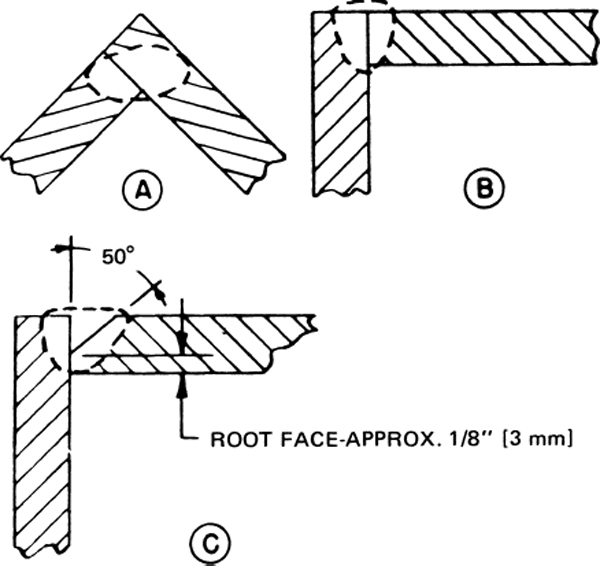
FIGURE 6-74 Corner joint.
All tee joints require the addition of filler rod to provide the necessary buildup. Such a joint is shown in Fig. 6-75. The number of passes on each side of the joint depends upon the thickness of the material and the size of the weld desired. When 100 percent penetration is required, the welding current must be adequate for the thickness of the web material.
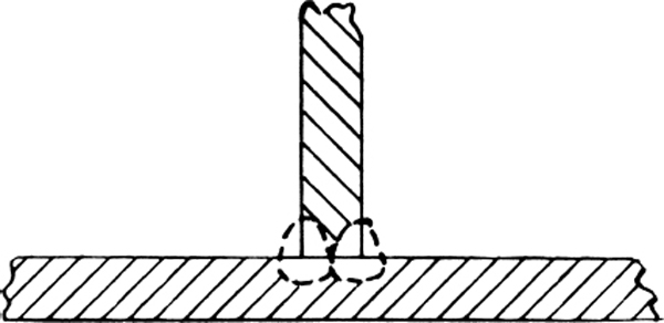
FIGURE 6-75 Tee joint.
A typical edge joint is shown in Fig. 6-76. Such joints are used solely on light-gauge material and require no filler rod. Preparation is simple, and the joint is economical to weld. This type of joint should not be used, however, where direct tension or bending stresses will be applied to the finished joint because it will fail at the root under relatively low stress loads.
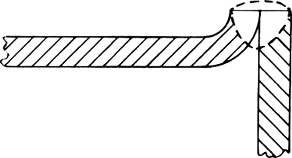
FIGURE 6-76 Edge joint at a corner.
Weld Backup
On many TIG welding applications, the joint should be backed up. This is done for several reasons. On light-gauge material, backing is usually used to protect the underside of the weld from atmospheric contamination resulting in possible weld porosity or poor surface appearance. In addition to these functions, weld backup prevents the weld puddle from dropping through by acting as a heat sink and drawing away some of the heat generated by the intense arc. The backup also can physically support the weld puddle. A TIG weld can be backed up by (1) metal backup bars, (2) introducing an inert-gas atmosphere on the weld underside, (3) a combination of the first two methods, or (4) use of flux backing painted on the weld underside.
Flat, metal backup bars are generally used on joints where the bar does not actually touch the weld zone. If the bar comes in contact with the underside of the weld, nonuniform penetration may occur and the weld underside may be rough and uneven.
A type of backup bar more commonly used is that shown in Fig. 6-77 where the surface is cut or machined out directly below the joint. On square-edge butt joints, for example, where fit-up is not too accurate and filler rod is required, a bar of this sort will protect the bottom of the weld from excessive contamination by the atmosphere and will draw the heat away from the weld zone.
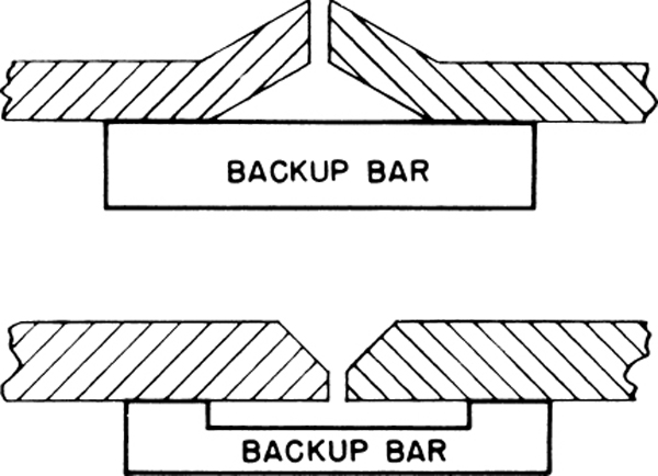
FIGURE 6-77 Use of a backup bar with a cutout.
Gas Tungsten-Arc Welding (GTAW)
Equipment for (GTAW)
The equipment used for gas tungsten-arc welding (GTAW) consists primarily of a power supply, a torch, and a gas supply, together with connecting hoses and cables. For torches that require cooling, a water system must be included.
The power supply for GTAW can be the same as that employed for standard arc (stick-electrode) welding, or it may be especially designed for inert-gas welding. A portable power supply unit for Heliarc welding is shown in Fig. 6-78. The power supply shown in Fig. 6-78 is the Linde HDA 300 welder, which can supply 300 A for a 60 percent duty cycle. The unit also includes the gas cylinder, gas-pressure and flow regulator, and tow cart. When purchased as a complete welding unit, the torch, connecting lines, and other accessories are included.

FIGURE 6-78 A portable power supply unit. (Anderson Equipment Company)
Gas tungsten-arc welding can be accomplished with direct-current, straight polarity (dcsp); direct-current, reverse polarity (dcrp); or with alternating-current, high-frequency stabilized (achf) power. Achf or dcrp power is generally recommended for magnesium and aluminum alloys and castings, whereas dcsp power is recommended for stainless steel, copper alloys, nickel alloys, titanium, low-carbon steel, and high-carbon steel. Achf or dcrp provides the best results with beryllium-copper alloys or copper alloys less than 0.040 in [0.016 mm] thick.
The effects of different types of current may be understood by studying the diagrams of Fig. 6-79. In direct-current welding, the welding current may be looked up as either straight polarity (SP) or reverse polarity (RP). The machine connection for dcsp welding is with the electrode negative and the work positive. The electrons will then flow from the electrode to the work, as shown in the illustration.

FIGURE 6-79 Action of different types of welding current.
For dcrp welding, the connections are reversed and the electrons flow from the work to the electrode. The following explains why dcrp or achf power is required for aluminum welding. The oxide coating on aluminum has a much higher melting point than aluminum and interferes with the fusion of the metal. With dcrp power, the electrons leaving the surface of the base metal break up the oxides as they flow to the electrode. This same effect takes place during one-half of each ac cycle when achf power is used.
In straight-polarity welding, the electrons hitting the plate at a high velocity exert a considerable heating effect on the plate. In reverse-polarity welding, just the opposite occurs; the electrode acquires this extra heat, which then tends to melt the end. Thus, for any given welding current, dcrp requires a larger-diameter electrode than dcsp. For example, a -in-diameter [1.59-mm] pure-tungsten electrode can handle 125 A of welding current under straight-polarity conditions. If the polarity were reversed, however, this amount of current would melt off the electrode and contaminate the weld metal. Hence, a -in-diameter [6.35-mm] pure-tungsten electrode is required to handle 125-A dcrp satisfactorily and safely.
These opposite heating effects influence not only the welding action but also the shape of the weld obtained. Dcsp welding will produce a narrow, deep weld; dcrp welding, because of the larger electrode diameter and lower currents generally employed, gives a wide, relatively shallow weld. The difference is illustrated in Fig. 6-80.
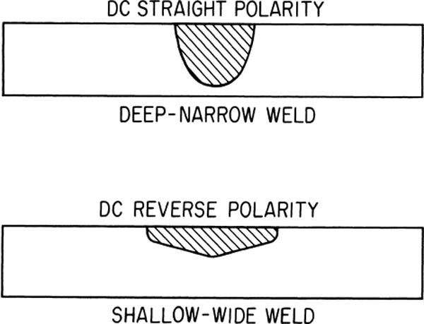
FIGURE 6-80 Effects of different polarities on the weld.
One other effect of dcrp welding should be considered here, namely, the cleaning effect. The electrons leaving the plate or the gas ions striking the plate tend to break up the surface oxides, scale, and dirt usually present.
Theoretically, straight ac welding is a combination of dcsp and dcrp welding. This can be explained by showing the three current waves visually. As illustrated in Fig. 6-81, half of each complete ac cycle is dcsp and the other half is dcrp. Actually, however, moisture, oxides, scale, and other materials on the surface of the work tend to prevent the flow of current in the reverse-polarity direction. This effect is called rectification. For example, if no current at all flows in the reverse-polarity direction, the current wave will look something like the curve in Fig. 6-82.

FIGURE 6-81 Illustration of ac wave through one cycle. (Linde Div., Union Carbide Corp.)
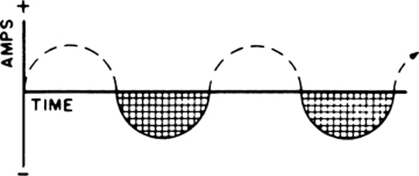
FIGURE 6-82 Rectified wave through two cycles with reverse polarity completely rectified. (Linde Div., Union Carbide Corp.)
To prevent the effects of rectification, it is common practice to introduce into the welding current a high-voltage, high-frequency, low-power additional current. This high-frequency current jumps the gap between the electrode and the workpiece and pierces the oxide film, thereby forming a path for the welding current to follow. Superimposing this high-voltage, high-frequency current on the welding current provides the following advantages:
1. The arc may be started without touching the electrode to the workpiece.
2. Better stability of the arc is obtained.
3. A longer arc is possible. This is particularly useful in surfacing and hard-facing operations.
4. Welding electrodes have a longer life.
5. The use of wider current ranges for a specific-diameter electrode is possible.
A typical weld contour produced with high-frequency stabilized alternating current is shown in Fig. 6-83, together with both dcsp and dcrp welds for comparison.
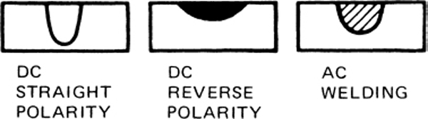
FIGURE 6-83 Comparison of dcsp and dcrp with achf weld. (Linde Div., Union Carbide Corp.)
GTAW Torch
A typical torch for inert-gas welding is illustrated in Fig. 6-84. This is the Linde HW-17 torch, suitable for thin to medium metal thicknesses. The torch consists of the collet and collet body to hold the tungsten electrode, the gas lens for controlling and directing the gas flow, the gas cup, the handle through which current and gas flow, and supporting structures.
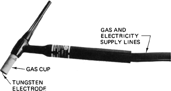
FIGURE 6-84 A torch for inert-gas welding. (Linde Div., Union Carbide Corp.)
Electrode Selection
The technician must select the proper electrode diameter and shape. The chemical compositions of various types of electrodes are shown in Table 6-5. The diameter of the electrode must be large enough to carry the required amperage.
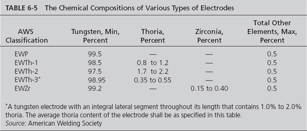
The shape of the electrode depends upon the material composition of the electrode, the amount of current being used during the process, and the characteristics of the desired joints. Figure 6-85 shows the different shapes of GTAW electrodes.
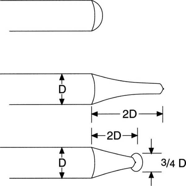
FIGURE 6-85 The different shapes of GTAW (TIG)electrodes. (Lincoln Electric Co.)
Filler Rod Selection
The filler rod must be metallurgically compatible with the metal being welded. Table 6-6 shows the recommended filler rod for various types of aluminum. The filler rod manufacturer’s recommendations should be referred to when welding other or dissimilar metals.

Gas Selection
GTAW uses either argon, helium, or a mixture of the two gases. Argon provides the smoothest arc action because the arc is more stable, the arc is easier to initiate, and wider variations to the length of the arc are possible. Because argon is heavier than air, the gas envelope does not dissipate as quickly as that of helium; argon is typically more economical than helium, however.
Helium, on the other hand, will raise the arc’s temperature for a given arc length and amperage. These elevated temperatures are employed when GTAW is used to weld nonferrous material thicker than in [6.35 mm]. A mixture of helium and argon produces higher temperatures and arc stability.
GTAW Equipment Setup and Check
Table 6-7 shows the generic setup relationships for the welding of various thicknesses of aluminum, types of joints, and welding positions. The column “Number of Passes” refers to the multipass welding techniques discussed later in this chapter.
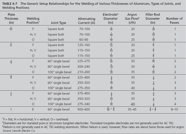
Before starting to weld, the entire welding setup should be thoroughly checked. It is most important to use the proper-size electrode and gas cup. All components must be functioning properly to realize the full advantage of this type of welding. The following instructions can be used as a guide:
• Check all connections in the gas supply line for tightness. Be sure that good seals are obtained between the torch body, the cap, and the gas cap, because any air leakage into the gas stream will contaminate both the weld and the electrode. Be sure any gaskets required are in good condition and are firmly in place. After welding, the electrode should have a clean, silvery appearance upon cooling. A dirty, rough electrode surface usually signifies air leakage in the torch or gas supply system.
• Check the welding current and gas-flow settings. They should be preset to the approximate values recommended for the material being welded.
• Select the proper gas cup and electrode size and electrode extension. The electrode should extend beyond the edge of the gas cup 1 to 1 times the diameter of the electrode. Fig. 6-86 depicts this relationship.
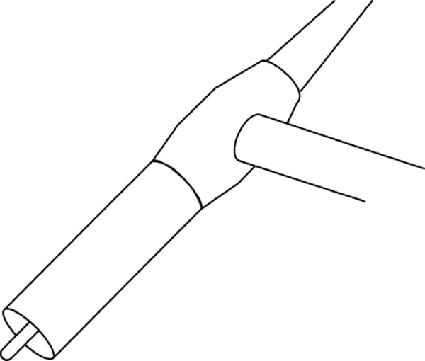
FIGURE 6-86 The electrode should extend beyond the edge of the gas cup.
• Check the rate of water flow through the torch if it is the water-cooled type. Flow rates lower than those recommended decrease torch efficiency and may result in damage to the torch, particularly if the torch is being used at or near its maximum capacity.
• Check the ground connection to be sure it is securely clamped to the workpiece. The workpiece should be cleaned at the point of contact, preferably by grinding, to ensure good contact.
• Check to ensure that the postflow timer is properly set. The postflow timer allows the gas to continue flowing through the torch for a designated time after the foot pedal is released. Postflow is necessary to prevent oxidation of the electrode while the electrode is cooling. The postflow timer is typically set to 10 s.
Starting an Arc
There is nothing difficult about starting an arc in the proper manner. The procedure explained in this section should ensure a good start and maximum protection of the work from atmospheric contamination at the start of the welding operation.
In arc welding with a tungsten electrode (TIG), the electrode does not have to touch the work to start the arc. The superimposed high-frequency current jumps the gap between the welding electrode and the work, thus establishing a path for the welding current to follow. To strike an arc, the torch is held in a horizontal position about 2 in [5.08 cm] above the work or starting block, as shown in Fig. 6-87. The end of the torch is then swung quickly down toward the work so the end of the electrode is about in [3.18 mm] above the metal. The arc strikes at this distance. The downward motion should be made rapidly to provide the maximum amount of gas protection to the weld zone. The position of the torch when the arc strikes is shown in Fig. 6-88.

FIGURE 6-87 Torch in position ready to strike an arc.

FIGURE 6-88 Torch in position when arc is struck.
In dc welding, the same motion is used for striking the arc. In this case, however, the electrode must actually touch the work in order to start the arc. As soon as the arc is struck, the torch is withdrawn so the electrode is about in [3.18 mm] from the work. This prevents contamination of the electrode in the molten pool. High frequency is sometimes used to start a dc arc. This eliminates the need for touching the workpiece. The high-frequency current is automatically turned off by means of a current relay when the arc is started.
The arc can be struck on the workpiece itself or on a heavy piece of copper or scrap steel and then carried to the starting point of the weld. A carbon block should not be used for striking the arc because it is likely to contaminate the electrode and cause the arc to wander when welding with a hot electrode is commenced. The action must be very rapid because the arc tends to strike before the torch is in the proper position.
To stop an arc, the torch is merely snapped quickly back to the horizontal position. This motion must be made rapidly so the arc will not mar or damage the weld surface or work.
Arc Wandering
With the torch held stationary, the points at which an arc leaves the electrode and impinges upon the work may often shift and wave without apparent reason. This is known as arc wandering and is generally attributed to one of the following causes: (1) low electrode-current density, (2) carbon contamination of the electrode, (3) magnetic effects, and (4) air drafts. The first two causes are indicated by a very rapid movement of the arc from side to side, generally resulting in a zigzag weld pattern. The third cause, magnetic effect, usually displaces the arc to one side or the other along the entire length of the weld. The fourth produces varying amounts of arc wandering, depending upon the amount of air draft present.
When current density of the electrode is at a sufficiently high level, the entire end of the electrode will be in a molten state and will be completely covered by the arc. When too-low current density is used, only a small area of the electrode becomes molten, resulting in an unstable arc, which has poor directional characteristics and is difficult for the operator to control. Too-high current density results in excessive melting of the electrode.
When a carbon block is used to strike the arc, electrode contamination often results. As the electrode touches the carbon, the molten tungsten on the tip of the electrode forms tungsten carbide. This has a lower melting point than pure tungsten and forms a larger molten ball on the end of the electrode. This, in effect, reduces the current density at the electrode end and arc wandering occurs. The electrode can also be contaminated by touching it to the workpiece or filler rod. When electrode contamination occurs in any form, it is best to clean the electrode by grinding, breaking off the end, or using a new electrode.
Magnetic effects are not generally encountered and are too complex to be discussed fully in this text. The most common magnetic action on the arc, however, results from the magnetic field set up by the current flowing in the work. This field may tend to attract or repel the arc from the normal path. One method for remedying this condition is to alter the position of the ground connection on the work until the effects are no longer noticed.
Making a Butt Weld
After the arc has been struck with a TIG torch, as previously explained, the torch should be held at about a 75° angle to the surface of the work. The starting point of the weld is first preheated by moving the torch in small circles, as shown in Fig. 6-89, until a small molten pool is formed. The end of the electrode should be held approximately in [3 mm] above the work. When the puddle becomes bright and fluid, the torch is moved slowly and steadily along the joint at a speed that will produce a bead of uniform width. No oscillating or other movement of the torch, except for the steady forward motion, is required.
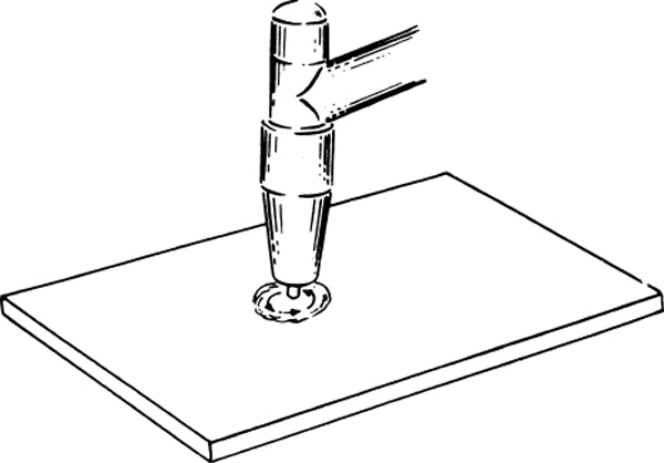
FIGURE 6-89 Forming the molten puddle.
When filler metal is required to provide adequate reinforcement, the welding rod is held at about 15° to the work and about 1 in [2.5 cm] away from the starting point. The starting point is then preheated, as explained previously, to develop the molten pool. When the puddle becomes bright and fluid, the arc is moved quickly to the rear of the puddle, and filler rod is added by quickly touching the leading edge of the puddle. The rod is removed and the arc is brought back to the leading edge of the puddle. As soon as the puddle becomes bright again, the steps are repeated. This sequence is continued for the entire length of the weld. Figure 6-90 illustrates the steps as described. The rate of forward speed and the amount of filler rod added depend on the desired width and height of the bead.

FIGURE 6-90 Steps in starting an inert-gas weld.
For making butt joints on a vertical surface, the torch is held perpendicular to the work and the weld is usually made from top to bottom. When filler rod is used, it is added from the bottom or leading edge of the puddle in the manner described previously. Figure 6-91 shows correct positioning of the rod and torch relative to the work.

FIGURE 6-91 Position of torch and filler rod for vertical GTAW (TIG) weld.
Making a Lap Weld
A lap weld, or joint, is started by first developing a puddle on the bottom sheet. When the puddle becomes bright and fluid, the arc is shortened to about in [2 mm]. The torch is then oscillated directly over the joint until the sheets are firmly joined. Once the weld is started, the oscillating movement is no longer required. The torch is merely moved along the seam, with the electrode held just above the edge of the top sheet.
In lap welding, the puddle developed will be boomerang or V-shaped, as shown in Fig. 6-92. The center of the puddle is called the notch, and the speed at which this notch travels will determine how fast the torch can be moved forward. Care must be taken to see that the notch is completely filled for the entire length of the seam. Otherwise, it is impossible to get 100 percent fusion and good penetration.

FIGURE 6-92 Shape of puddle in lap welding.
When filler metal is used, faster welding speeds are possible because the rod helps to fill the notch. Complete fusion must be obtained rather than allowing bits of filler rod to be laid into the cold, unfused base metal. The rod should be alternately dipped into the puddle and withdrawn in [6.35 mm], as illustrated in Fig. 6-93. By carefully controlling the melting rate of the top edge and by adding just enough filler metal where needed, a good uniform bead of correct proportions can be obtained.
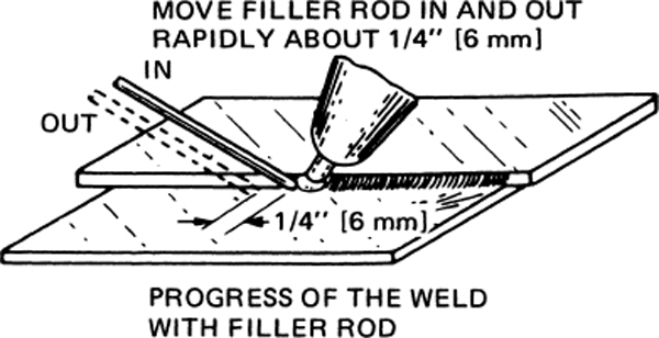
FIGURE 6-93 Procedure for lap welding with GTAW (TIG) welding.
Making a Corner, or Edge, Weld
The corner, or edge, weld is the easiest type to make. A puddle is developed at the starting point, and the torch is then moved straight along the joint. Rate of travel is regulated to produce a uniform bead. A too-slow welding speed will cause molten metal to roll off the edges. Irregular or too-high speeds will produce a rough, uneven surface. No filler metal is required.
Multipass Welding
Multipass welding is generally required for welding material over in [6.35 mm] thick. The number of passes required depends upon the thickness of the material, the current-carrying capacity of the equipment involved, and the assembly being fabricated. The first pass should be a root weld and should provide complete fusion at the bottom of the joint. Subsequent passes can be made at higher currents owing to the backup effect of the root weld. Care should be taken to prevent inclusions between weld layers. On heavy work, it is sometimes advantageous to carry all the beads along simultaneously in a staggered arrangement to utilize the residual heat of preceding passes.
Gas Metal-Arc (MIG) Welding (GMAW)
Gas metal-arc welding (GMAW) simplistically appears to be the same process as GTAW, except that the electrode is consumable and fed through the torch automatically. However, as the technician should be aware, they are really quite different. Figure 6-94 shows the front of a GMAW power supply and Fig. 6-95 illustrates a typical electrode wire-feeding system.

FIGURE 6-94 Front view of a GMAW (MIG) welding power supply. (Miller Electric Manufacturing Co.)
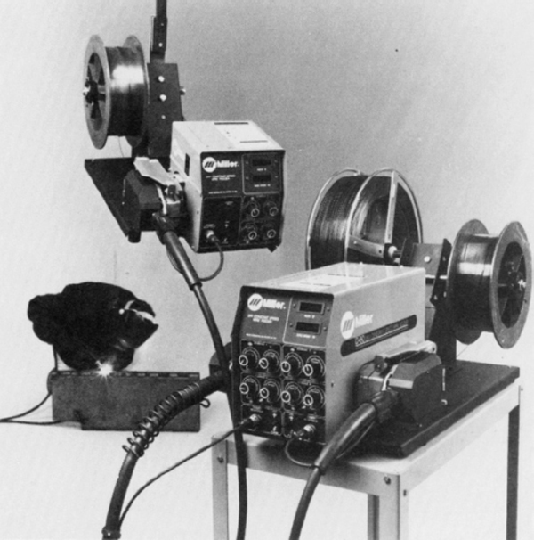
FIGURE 6-95 GMAW (MIG) wire-feed system. (Miller Electric Manufacturing Co.)
Two general techniques or processes are employed when welding with MIG (GMAW) in aviation maintenance applications. These are called spray-arc transfer and short-circuit transfer. Three other GMAW techniques exist but have either no or extremely limited aviation maintenance applications. They include buried-arc, pulsed-arc, and fluxed-cored welding. Taken as a whole, the GMAW techniques are capable of welding almost all metals in all types of configurations, in all positions.
In spray-arc transfer the metal from the electrode is carried to the molten pool in fine droplets by the force of the arc and by gravity. The power source for this process is constant-voltage direct current, reverse polarity. For best results with this process, the work should be level or nearly so. The shielding gas employed with spray-arc transfer is usually argon with 1 or 2 percent oxygen for stabilization of the puddle and arc. Of the five techniques mentioned here, spray-arc transfer is the most stable, offers the most directional flexibility, and is nearly splatter-free when properly accomplished.
When short-circuit transfer is used, the tip of the metal electrode is touched to the metal to provide a short circuit. This results in a high amperage, which melts the end of the electrode into the pool. The electrode is constantly fed into the pool to maintain the arc and transfer the metal.
When steel is welded with short-circuit transfer, the shielding gas can be pure CO2 or a mixture of CO2 and argon. For stainless steel, the mixture of gases is helium, argon, and CO2.
Buried-arc transfer uses carbon dioxide as the shield for the welding area. The carbon dioxide causes the filler metal to be globular in nature. These large drops increase the frequency of short circuits during the welding process and this results in a considerable amount of splatter.
Pulsed-arc welding involves the use of high-amperage pulsations during the process in order to reduce the average current. However, highly specialized power supplies are required and extensive operator training is required.
The fluxed-core method mentioned here is more properly known as gas-shielded flux-cored electrode welding. It differs from the self-shielded flux-cored electrode welding previously mentioned in that carbon dioxide gas acts as an external shield and from the traditional MIG welding because its core is tubular (not solid). Application of the flux-cored process in aviation is extremely limited and is therefore beyond the scope of this text.
Equipment for GMAW
Typically, GMAW requires the use of DCRP with a constant voltage supply. With a constant voltage the power controller will automatically maintain the amperage at a level that will melt the electrode. These power supplies are referred to as SVI power supplies because they control the slope, voltage, and inductance during the welding process.
The desired voltage is a function of a variety of factors. Table 6-8 shows the typical ac voltages recommended for a variety of materials and shielding-gas combinations. In addition to these factors, variables such as the type of electrode, type of joint, thickness of the material, and position of the weld all combine to determine the proper voltage.

Slope
For a given set of operating conditions, there is a relationship between the voltage and amperage required to establish the desired arc. This relationship may be graphically displayed by a straight line drawn between two such sets of voltage-amperage relationships. The slope of this line is the slope of the power source. Anything that changes the resistance of the welding circuit—for example, the length of the welding cables or loose connections—changes the slope of the power source. Figure 6-96 shows the relationship between two different slopes.
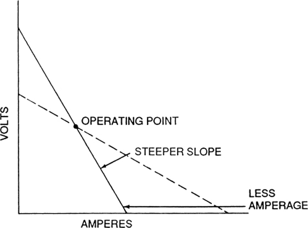
FIGURE 6-96 The relationship between two different slopes. (American Welding Society)
In GMAW, where a constant voltage is applied, the slope of the line is used to determine the resultant current. This current controls the way in which the molten droplets leave the electrode. High currents typically result in the droplets of molten material leaving the electrode in a violent fashion. This results in excessive splattering around the weld area. Low voltages result in a calmer flow of molten material from the electrode to the base material.
Inductance
The rate at which the current changes to reflect a new combination of welding variables—for example, the initiation of an arc—is called inductance. If this rate of current change is rapid, excessive splattering is the result. By adding inductance to the welding circuit, the rate of current change is decreased and a smoother weld can be established and maintained.
Also associated with this phenomenon is the slope of the power source. The “flatter” the slope of the line, the less the inductance.
Equipment Setup
The setup used for the power supply depends upon the type of arc desired. The short arcs require less voltage (16–20 V) and result in less heat, less fluidity of the molten metal droplets, and more splatter. For short arcs the slope of the power source should be set on a “flat” setting, with the inductance between the minimum setting and half of the scale. The voltage should be set to maintain an arc that is in [3.18 mm] to  in [2.38 mm] in length.
The spray arc mode requires a voltage between 20 and 30 V, needs higher heat, and results in more fluid-metal transfer and less splatter. The slope for the spray-arc mode should be “steep” and the inductance should be in the upper half of the inductance scale.
Another important factor in setting up the equipment for GMAW is the wire-feed rate. Since the wire is the electrode and the arc distance is controlled by the feed rate, if the wire feed rate is too great, the electrode will eventually contact the metal. If it is not fast enough, the electrode will burn back into the torch cup.
Selection of Electrode Wire
The selection of electrode wire for GMAW is similar to that of other bare filler rod. The recommendations of the equipment and wire manufacturers should always be followed. Some filler metals are very similar to the base metals, whereas others, such as the electrode wire for 6061 aluminum, are quite different.
The designation system for filler electrode wire established by the AWS is the same as that used for similar filler rod materials. Steel wire has an AWS designation of E70S-X, where the X is a sequential dash number indicating the exact wire chemistry. Aluminum wire is designated in the same way GTAW wire is designated. Stainless steel wire is again the same as the GTAW designation, except the prefix is “ER.” Copper and copper alloy wires have a prefix of “ECU” and a suffix indicating the chemical composition.
Starting the Weld
Since the technician is primarily concerned with restoring the workpiece to its original condition, setting up the equipment will need to be accomplished with the use of scrap materials of the same type and thickness as those being repaired. Once preliminary setup has been established, the technician should proceed using the scratch and retreat method.
The scratch and retreat method is designed to minimize the effect of beginning and ending the weld at the weld-joint ends. As previously noted when discussing other types of fusion welding, the dissipation of heat at the ends of the weld joint is less than in the body of the joint, resulting in poorer weld joints at the ends. However, since the structural load transfer is greatest at the beginning and ends of joints, this is the area that requires the best joint. The technician should use a scratch start technique approximately an inch from the end of the joint and then quickly move or retreat to the end of the joint and then proceed, using the normal welding process. At the end of the joint the torch should be moved from the end of the joint, retreating about 1 in. over the newly welded joint before the arc is terminated.
During the welding process the arc height should be maintained at approximately the same level; however, minor variations in height should not affect the weld quality. The torch should be maintained at an angle of 70° to 85° and moved in a forehand direction. The width of the bead may be established by the welder by controlling the torch angle and the rate of travel of torch. At the ends of the joints, only the rate of travel should be used to control the bead size.
Plasma-Arc Welding (PAW)
Plasma-arc welding (PAW) is a modification to the GTAW process. It takes advantage of the plasma section of the welding arc (see “Welding Arc”) by concentrating its flow through an orifice. By concentrating this area of the arc, temperatures ranging to 60 000°F have been developed, with theoretical temperatures up to 200 000°F potentially available. However, since the temperatures of GTAW exceed those normally required by the metals being welded, the main advantages of PAW are the directional stability of the plasma arc and the focusing of the arc by the orifice. Also, the temperature of the arc is not affected a great deal by minor changes in the torch’s stand-off distance. The plasma arc is in [6.35 mm] long, whereas the gas tungsten arc is approximately one-tenth that length.
There are two welding techniques available when plasma-arc welding, the melt-in technique (which is used in conventional GTAW) and the keyhole technique. The technician is most likely to use the low-amperage melt-in technique, since the high-amperage keyhole technique requires precise control of welding travel rates. The keyhole technique actually causes the molten puddle to extend completely through the part. The molten metal is then forced by the velocity of the arc to flow around it and to the rear of the arc stream, where the molten material solidifies. The keyhole technique is usually limited, in practice, to machine welding applications.
The power source may be the same as that used in GTAW. However, the torch must have extremely good cooling capabilities to use DCRP due to the increased temperatures.
The plasma gas, an ionized column of gas that passes from the anode to the cathode, may be supplemented by an inert shielding gas. The orifice gas need only be inert to tungsten (the electrode material). The supplemental shielding gas need not be inert, but must not adversely affect the properties of the weld joint. Typically the orifice gas is either argon (Ar), helium (He) or an argon-helium (Ar-He) mixture, depending upon the material, the material thickness, the current, and type of welding technique employed. The shielding gas is either argon, an argon-helium mixture or an argon-hydrogen mixture. Tables 6-9 and 6-10 show the recommended combinations for high- and low-current plasma-arc welding, respectively.
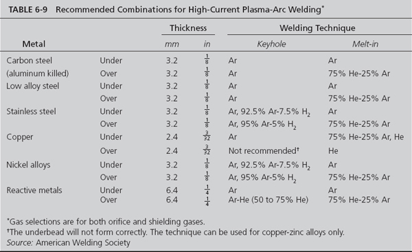

In plasma-arc welding the workpiece may not be required to be part of the electric circuit. The heat used in the plasma-arc process for cutting or welding is transferred to the workpiece through the plasma gas rather than the arc itself. This phenomenon significantly lessens the problems encountered by other inert-gas welding processes, such as arc wander, and the high velocity of the plasma gas reduces arc deflection.
Plasma-arc welders are classified as transfer and non-transfer. Transfer plasma-arc welders include the work-piece as part of the electric circuit. Nontransfer plasma-arc welders do not. Figure 6-97 illustrates the difference between the transfer and the nontransfer modes.

FIGURE 6-97 The difference between the transfer and the nontransfer modes. (American Welding Society.)
The function of the orifice, found in the torch, is to direct and accelerate the plasma gas toward the workpiece. In the nontransfer application the orifice material also acts as the cathode for the electric circuit.
In addition to the general practical application advantages of plasma-arc welding, the primary advantage of nontransfer plasma-arc welding to the aviation maintenance technician is that the aircraft itself no longer needs be part of the electrical circuit, which is a requirement of the more traditional electric welding processes. This eliminates the concerns about magnetizing the welded material and the magnetic induction of current into electrical lines and instruments.
Electrode selection
The electrodes used in PAW are the same materials as GTAW. The electrode, however, must be round and concentric. The tip of the electrode is not extended past the orifice cup, helping to eliminate electrode contamination. The tip of the electrode is ground to an included angle between 20° and 60°, with the end being either sharp or flat.
Starting the Arc
Because the electrode does not extend beyond the orifice, the arc may not be started by using the touch-start technique. Instead a pilot-arc system is employed, which may use either a separate power source or the welding power source, if properly designed. Not only does the pilot arc start the plasma arc, but it is also useful in positioning the torch for the plasma-arc welding process. The pilot-arc is terminated once the plasma-arc process is initialed.
Rod Selection
The rod selection process is the same as in the GTAW welding process.
Manual Paw Welding Procedures
The technician is most likely to use the manual torch in a maintenance environment. The similarities between GTAW and PAW make this transition relatively easy. For many, plasma-arc welding is likely to be easier. The standoff distance is less critical when using PAW. PAW standoff may vary from in [3.18 mm] to in [6.35 mm] without affecting the process. The stability of the arc voltage in plasma welding provides for greater control when welding materials that require low currents. Figure 6-98 compares the volt-amperage characteristics between GTAW and PAW in argon. The relative flatness of the plasma-arc (upper) line exemplifies the stability of the relationship.
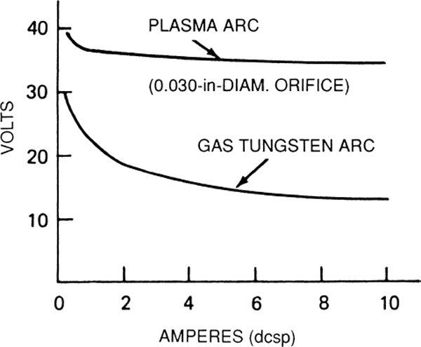
FIGURE 6-98 Comparison of the volt-amperage characteristics between GTAW (MIG) and PAW (plasma) in argon.
The recommended torch angle of 25° to 35° is only slightly more steep than the GTAW torch angle (15°). A forehand technique is recommended for PAW processes. The filler rod, when required, is applied in the same manner as in GTAW techniques. The torch-movement pattern is the same as GTAW as they relate to bead shape, size, and penetration. Weld joint designs are similar, as are fixturing and backup plate techniques.
Friction-Stir Welding Process
A new type of welding process used in the aerospace industry is friction-stir welding (FSW). This type of welding is a production-type solid-state (meaning the metal is not melted) welding process and is used for applications where the original metal characteristics must remain unchanged as far as possible. The welding equipment is automated to obtain a high accuracy and repeatability of the welds. This technique utilizes a nonconsumable rotating welding tool to generate frictional heat and deformation at the welding location, thereby affecting the formation of a joint, while the material is in the solid state. Figure 6-99 shows the rotating tool.

FIGURE 6-99 Friction stir welding terminology.
The metal is fused using mechanical pressure, much like joining clay, dough, or plasticine. This process is primarily used on aluminum, and most often on large pieces which cannot be easily heat treated after the weld is completed to recover temper characteristics. The principal advantages of FSW, being a solid-state process, are low distortion, absence of melt-related defects, and high joint strength, even in those alloys that are considered non-weldable by conventional techniques (e.g., 2xxx and 7xxx series aluminum alloys). Furthermore, friction-stir (FS)–welded joints are characterized by the absence of filler-induced problems and defects, since the technique requires no filler. Finally, the hydrogen content of FSW joints tends to be low, which is important in welding steels and other alloys susceptible to hydrogen damage. The Eclipse Aerospace Company has used friction stir welding for the primary structure of the Eclipse Jet since it received FAA approval in 2002. Figure 6-100 shows the welding process. Besides Eclipse other companies that use FSW include Boeing, Airbus, BEA, Lockheed Martin, NASA, US Navy, Mitsubishi, Kawasaki, Fokker as well as other industrial companies in the United States, Europe, and Japan.

FIGURE 6-100 Automated friction-stir welding process.
CONCLUSION
In welding with any particular type of equipment, the technician should consult the manual supplied with the equipment to ensure that the most effective gases and techniques are employed.
In this section we have explained common types of gas and electric-arc welding. Oxyacetylene is the most common form of welding used in the aviation maintenance field. The plain electric-arc (stick-electrode) system is commonly used for heavy industrial construction in steel. Inert-gas welding, on the other hand, is used in a wide variety of precision welding on many different types of metals and alloys. For this reason it is particularly well adapted for welding structures and parts for aerospace vehicles.
There are many other types of welding, such as submerged-arc and electron-beam welding. These are specialties and are usually practiced by highly skilled welders. They are not usually done by the average airframe and powerplant technician; hence, detailed descriptions of these processes are considered beyond the scope of this text.
REVIEW QUESTIONS
1. What is meant by fusion welding?
2. Why is it usually necessary to add metal in the form of a welding rod while making a weld?
3. List the items necessary for a complete portable welding outfit.
4. Briefly describe acetylene gas and explain why it is used in gas welding.
5. At what pressures does acetylene gas become unstable and in danger of exploding?
6. What material is placed inside an acetylene cylinder to absorb the gas and thus ensure safe handling?
7. What is the maximum pressure of the gas in an acetylene cylinder?
8. Why is it necessary to keep oxygen equipment free from oil or grease?
9. To what pressure is an oxygen cylinder charged?
10. How can you determine the volume of gas in an oxygen cylinder?
11. Discuss the importance of a protector cap over the valve on an oxygen cylinder.
12. Describe a gas-pressure regulator and explain its function.
13. Why are two pressure gauges used on a cylinder gas regulator?
14. List the main differences between an oxygen-pressure regulator and an acetylene-pressure regulator.
15. How does a welder adjust the gas regulator to increase pressure?
16. Name the two principal types of welding torches.
17. Which type of welding torch is generally preferred for aircraft welding? Why?
18. Explain the function of the mixing head.
19. What determines the size of tip to be used in a welding torch?
20. How are oxygen and acetylene torch hoses identified?
21. How is the danger of incorrectly connecting the hoses avoided?
22. What are the two principal functions of welding goggles?
23. Why should a friction lighter be used to ignite the gas at the tip of an oxyacetylene welding torch?
24. Briefly describe the steps for setting up oxyacetylene welding apparatus.
25. What method should be used in testing for oxyacetylene leaks?
26. In lighting an oxyacetylene welding torch, what gas should be turned on first?
27. Explain how to adjust the oxyacetylene torch for a neutral flame.
28. Why is a neutral flame best for welding steel?
29. Describe the appearance of a neutral oxyacetylene flame.
30. What is the effect of using an oxidizing oxyacetylene flame?
31. Compare the carbonizing (carburizing) flame with the oxidizing flame.
32. What is the effect of a damaged or obstructed oxyacetylere welding torch tip orifice?
33. Explain how a gas welding torch tip can be cleaned properly.
34. Why is a soft flame better than a harsh flame for welding?
35. What are some of the causes of popping at the welding tip?
36. Give the procedure for shutting down the oxyacetylene welding apparatus.
37. Discuss the knowledge of welding necessary for the technician.
38. How should the welding torch be held for heavy welding?
39. Explain the difference between forehand and backhand welding.
40. Explain the purpose of the filler rod.
41. Approximately how far should the oxyacetylene welding flame cone be held from the base metal?
42. Describe the application of welding rod to the weld.
43. Explain circular and semicircular motions of the torch.
44. At what angle is the oxyacetylene torch flame applied to the metal?
45. Name the four common positions of a weld.
46. Describe how metal is prepared for welding.
47. Why are the edges of the metal beveled in many cases?
48. Describe a butt joint in welding.
49. Why is it not necessary to use filler rod when welding a flange butt joint?
50. Under what conditions is a double-V tee joint used?
51. Describe a single-welded lap joint.
52. Name the various parts of a weld.
53. What are the three most important proportions of a weld?
54. What should be the width of the welding bead?
55. What should be the depth of penetration in welding?
56. What are the usual causes of improperly formed weak welds?
57. Describe the chemical changes that may take place during gas welding.
58. What is the effect of expansion in welding?
59. Explain coefficient of expansion.
60. What precautions must be taken in welding a closed metal assembly?
61. Discuss the effect of high temperatures on the strength of metals.
62. What actions can a welder take to reduce the effects of distortion and residual stresses?
63. Explain stagger welding and skip welding.
64. What is the purpose of a welding fixture?
65. When welding heavy plate, how may welding stresses be reduced?
66. How is preheating accomplished?
67. Explain stress relieving.
68. What is meant by the spark test for the identification of metals?
69. Describe a good-quality completed weld.
70. What is meant by the bend test for a weld?
71. What type of flame should be used for aluminum and magnesium welding?
72. How are the edges of thin aluminum sheet prepared for gas welding? Aluminum plate over 0.25 in [6.35 mm] thick?
73. Describe procedures for making magnesium butt welds with a gas-welding process.
74. Describe the process of electric-arc welding.
75. Describe the electrode for arc welding.
76. What are two functions of the electrode?
77. What is the purpose of the coating on the electrode?
78. Describe the welding circuit.
79. What is the nature of the power used for electric-arc welding with respect to voltage and amperage?
80. What type of devices supply the power for arc welding?
81. Describe what takes place in the welding arc.
82. What temperature is developed in the arc?
83. Explain the three types of current that may be used for arc welding.
84. Describe inert-gas or gas-arc welding.
85. What is the nature of the electrode used with inert-gas welding?
86. Explain the difference between TIG and MIG welding.
87. Give the advantages of inert-gas welding.
88. What equipment is necessary for doing inert-gas welding?
89. What types of electrical power are used with inert-gas welding?
90. What is the difference in the effects of dcsp and dcrp current?
91. Why is dcrp or achf power required for welding aluminum and magnesium?
92. Why is a larger electrode required for dcrp welding power?
93. What are the advantages of achf power?
94. Describe two techniques that can be used with MIG welding.
95. Name five basic joints for inert-gas welding.
96. How should metal be prepared before inert-gas welding is started?
97. Why is a weld backup used with some welds?
98. List the checks that should be made before inert-gas welding is started.
99. Describe the process of striking an arc.
100. Why is it undesirable to strike the arc on a carbon block?
101. What is meant by arc wandering?
102. What are the principal causes of arc wandering?
103. Describe the process of starting an inert-gas weld.
104. What is meant by a multipass weld?
..................Content has been hidden....................
You can't read the all page of ebook, please click here login for view all page.