

Aircraft Fluid Power Systems |
13 |
INTRODUCTION
Hydraulic and pneumatic systems in aircraft provide a means for the operation of large aircraft components. The operation of landing gear, flaps, control-boost systems, and other components is largely accomplished with hydraulic power systems. Pneumatic systems are used in some aircraft designs to perform the same type of operations performed by hydraulic systems. However, the majority of aircraft that have pneumatic systems use them only as backup systems for the operation of hydraulic components when the hydraulic system has failed.
PRINCIPLES OF HYDRAULICS
Hydraulics is a division of the science of fluid mechanics that includes the study of liquids and their physical characteristics, both at rest and in motion. The type of hydraulics applied to aircraft and other aerospace-vehicle systems is called power hydraulics because it involves the application of power through the medium of hydraulics. Among the uses of hydraulic systems in aerospace-vehicle systems are the operation of landing gear and gear doors, flight controls, brakes, and a wide variety of other devices requiring high power, quick action, and/or accurate control.
Hydraulic Terms
It is necessary to understand the exact meaning of hydraulic terms in order to understand hydraulic principles and their application to hydraulic systems. These terms are defined as follows.
Area is a measurement of a surface. In aircraft hydraulics the technician is concerned with the areas of piston heads. Knowing this area, the amount of force required to actuate a mechanism can be determined. Area is generally measured in square inches in the English system and square centimeters in the metric system.
Force is the amount of push, pull, or twist on an object. The force in a hydraulic system is derived from the pressure acting on the area of a piston head. In the English system, force is measured in pounds; in the metric system, it is measured in grams, kilograms, or newtons (N). To measure the force of hydraulics, we must be able to determine force per unit area. This is called pressure and is measured in pounds per square inch (psi) or kilopascals (kPa).
Stroke (length) is a measurement of distance expressed in inches or centimeters, and it represents the distance a piston moves in a cylinder.
Volume (displacement) is a measure of quantity, expressed in cubic inches or liters, which represents the amount of fluid contained in a reservoir or displaced by a pump or actuating cylinder.
Fluid is any substance that is liquid or gaseous in form. A liquid is a fluid whose particles form a definite volume. The term hydraulic fluid is used in this text as the common name for the fluid used in aircraft hydraulic systems and devices.
In general, fluids expand when they are heated and contract when they are cooled. If a fluid is confined so that it cannot escape when it is heated, pressure on the walls of the confining vessel will increase. Cooling of a confined fluid under pressure will cause a decrease in pressure.
Relationship of Terms
The terms area, pressure, force, stroke, and volume are mathematically related. This relationship establishes the foundation upon which hydraulic systems are based. It permits the technician to determine the operating pressures required for certain units in a system, the size of pump required, the requirements for strength of the material in system units, the size of tubing required, and the area and length of stroke of the actuating cylinders. Consider the relationship of force, pressure, and area. If any two of these factors are known, it is possible to calculate the third. Force equals pressure times area (F = P × A), pressure equals force divided by area (P = F/A), and area equals force divided by pressure (A = F/A). A simple aid for solution of problems involving these factors is the diagram shown in Fig. 13-1. For example, suppose a force of 100 lb is exerted on a piston whose area is 4 in2. That pressure is the amount of force per unit of area expressed in psi; therefore, on each square inch of the piston there are 25 lb of force, or 25 lb/in2 (psi). The indicated mathematics is: Divide force (100 lb) by area (4 in2), and the answer obtained will be 25 psi [172.4 kPa], which represents pressure (P). If force is unknown, cover F and multiply A by P. If area is unknown, cover A and divide F by P.

FIGURE 13-1 Relationship of force, area, and pressure.
In general, and for practical purposes, liquids are regarded as being incompressible. This means that the volume of a given quantity of a liquid will remain constant even though it is subjected to high pressure. Because of this characteristic, it is easy to determine the volume of hydraulic fluid required to move a piston through its operating range. For example, if a piston is 4 in [10.16 cm] in diameter and its stroke is 10 in [25.4 cm], the volume of liquid necessary to move the piston through its full stroke is 125.67 in3 [2.06 L]. This is determined as follows.
The volume of the cylinder through which the piston moves is equal to the area of the piston head multiplied by the length of the cylinder. The area of the piston head is determined by the formula A = πr2; therefore, for the piston in the example, A = 3.1416 × 22 = 12.567. Multiplying this value by 10, we obtain the volume 125.67 in3 [2.06 L]. We know then that it will require 125.67 in3 of hydraulic fluid to move the piston through its 10-in [25.4-cm] stroke.
Because of the relative incompressibility of a liquid, we know that a given output volume from a hydraulic pump will provide an equal volume of fluid at the operating unit. For example, if a hydraulic pump discharges 100 in3 [1.639 L] of fluid through a filled connecting line between the pump and an actuating cylinder, the piston in the cylinder will have to move through sufficient distance to provide a volume of 100 in3 [1.639 L] to accommodate the fluid.
Hydraulic fluids and other liquids expand as temperature increases; therefore, safeguards must be provided in hydraulic systems to allow for the expansion and contraction of fluid as temperature changes.
A confined liquid will seek its own level, as shown in Fig. 13-2. Here the liquid is in a container open at the top and is subjected only to the force of gravity. Assuming that the container shown in the illustration is level, the pressure is the same at all points on the bottom of the container. The liquid surfaces at A, B, C, and D are all equidistant from the bottom of the container.

FIGURE 13-2 Liquid seeks its own level.
A basic principle of hydraulics is expressed in Pascal’s law, formulated by Blaise Pascal in the seventeenth century. This law states that a confined hydraulic fluid exerts equal pressure at every point and in every direction in the fluid. The law holds under static conditions and when the force of gravity is not taken into consideration. In Fig. 13-3 if the piston has a face area of 1 in2 [6.45 cm2] and a force of 10 lb [44.48 N] is applied to it, the fluid in the container will exert 10 psi [68.95 kPa] in all directions on all surfaces within the container. In actual practice the weight of the fluid would cause a small increase in the pressure on the bottom and lower sides of the container.

FIGURE 13-3 Fluid pressure is the same in all directions.
When liquids are in motion, certain dynamic characteristics must be taken into consideration. One of the principal factors in liquid motion is friction. Friction exists between the molecules of the liquid and between the liquid and the pipe through which it is flowing. The effects of friction increase as the velocity of liquid flow increases. The result of friction can be seen in the simple experiment illustrated in Fig. 13-4.

FIGURE 13-4 Reduction of pressure because of friction.
As the liquid flows from the container through a pipe that is open at the end, the pressure of the liquid decreases progressively until it becomes 0 psi at the open end of the pipe. If the pressure at A is 4 psi [27.58 kPa], then it will be 3 psi [20.69 kPa], 2 psi [13.79 kPa], 1 psi [6.895 kPa], and 0 psi at B, C, D, and E, respectively. As liquid velocity increases through a given length of pipe, the pressure differential between the ends of the pipe will increase. The same is true when a liquid is flowing through a restriction in a pipe. For this reason, the rate of fluid flow can be determined by measuring the pressure differential on opposite sides of a given restrictor. This is illustrated in Fig. 13-5. The differential pressure reading on the gauge will increase as liquid velocity through the restrictor increases, and the reading of the gauge can be converted to gallons per minute or some other rate measurement.
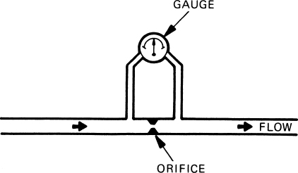
FIGURE 13-5 Differential pressure across an orifice.
Friction in a moving liquid produces heat, and this heat represents a loss of energy in a hydraulic system. According to the law of conservation of energy, which states that energy can neither be created nor destroyed, energy converted to heat must be subtracted from the total energy of the moving liquid. Therefore, if a hydraulic pump is discharging hydraulic fluid at a rate and pressure equivalent to 3 hp [2.24 kW] and in the system the equivalent of 0.2 hp [0.149 kW] is converted to heat, the power available for useful work is reduced to 2.8 hp [2.09 kW).
Performing Work with a Liquid
One of the principal advantages of hydraulics is the fact that force can be multiplied to almost any degree by the proper application of hydraulic pressure. In the diagram of Fig. 13-6, a piston and cylinder with a diameter of 2 in [5.08 cm] is used to develop a force of 2500 lb [11 125 N] by acting through a cylinder with a diameter of 10 in [25.4 cm]. The area of the 2-in [5.08-cm] piston is 3.1416 in2 [20.27 cm2]. The area of the 10-in piston is then 5 × 3.1416, or 78.54 in2 [506.71 cm2]. When a force of 100 lb [444.8 N] is applied to the small piston, a pressure of 100/3.1416, or 31.83 psi [219.47 kPa] is developed in the system. The force exerted by the large piston is then 31.83 × 78.54, or approximately 2500 lb [11 120 N]. Note that the areas of circles are proportional to the squares of the diameters; therefore, the force developed by one piston driving another is also proportional to the squares of the diameters. In the foregoing problem, the square of the diameter of the smaller piston is 2 × 2, or 4, and the square of the larger piston is 10 × 10, or 100. The ratio is then 4: 100, or 1.25. Since the force applied to the small piston is 100 psi [689.5 kPa], the force delivered by the large piston is 100 × 25, or 2500 lb [11 125 N].

FIGURE 13-6 Multiplication of force by means of hydraulics.
Since energy cannot be created or destroyed, the multiplication of force is accomplished at the expense of distance. In the foregoing problem, the ratio of force multiplication is 25:1. The distance through which the pistons move must then be in an inverse ratio, or 1:25. That is, the large piston will move one twenty-fifth the distance the small piston moves. If the small piston is connected to a fluid input with check valves so it can act as a pump, it can be moved back and forth, and during each forward stroke it will move the large piston a short distance. This action can be observed in the hydraulic jacks used to raise airplanes.
In some aircraft hydraulic systems, fluid pressures of as much as 5000 psi [34 475 kPa] are employed. With a pressure of this level, a very small actuating cylinder can exert tremendous force. For example, a cylinder having a cross-sectional area of 2 in2 [12.9 cm2] can exert a force of 10 000 lb [44 480 N].
A Simple Hydraulic System
Basically, a hydraulic system requires a source of hydraulic power (the pump); pipes or hoses to carry the hydraulic fluid from one point to another; a valve mechanism to control the flow and direction of the hydraulic fluid; a device for converting the fluid power to movement (actuating cylinder or hydraulic motor); and a reservoir to store the hydraulic fluid.
A simple hydraulic system is shown in the diagram of Fig. 13-7. The pump (P) draws hydraulic fluid from the reservoir (R) and directs it under pressure to the four-way selector valve (V). When the selector valve is in the position shown, the fluid will flow into the left end of the actuating cylinder (A) and force the piston to the right. This moves the piston rod and any device to which it is connected.
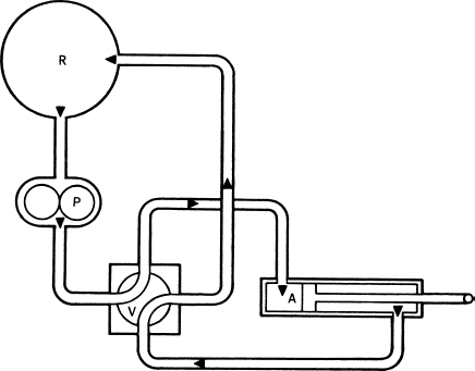
FIGURE 13-7 A simple hydraulic system.
As the piston moves to the right, the fluid to the right of the piston is displaced and flows out the port at the right end of the cylinder, through the tubing to the valve, and from the valve to the reservoir. When the valve is rotated one-quarter turn, the reverse action will take place.
It must be emphasized that the diagram shown is not intended to illustrate an actual system but only to illustrate the principle of a hydraulic system. In an actual system, a pressure regulator or relief valve is necessary between the pump and the valve in order to relieve the pressure when the cylinder reaches the end of its travel. Otherwise, the pump would be damaged or the tubing would burst.
Another simple system is illustrated in Fig. 13-8. This system is similar to a hydraulic brake system. Hydraulic fluid is stored in the cylinder and is directed through a valve into the master cylinder as it is needed. When the brake pedal is depressed, the fluid is directed to the brake cylinders; these cylinders push the shoes apart, thus causing them to bear against the brake drum and provide brake action. When the pedal is released, springs attached to the brake shoes cause the shoes to contract and push inward on the brake cylinders, thus causing some of the fluid to return to the master cylinder.

FIGURE 13-8 Hydraulic brake system.
HYDRAULIC FLUIDS
Purposes of Hydraulic Fluids
Hydraulic fluids make possible the transmission of pressure and energy. They also act as a lubricating medium, thereby reducing the friction between moving parts and carrying away some of the heat.
Types of Hydraulic Fluid
There are three principal types of hydraulic fluids: vegetable-base fluids, mineral-base fluids, and phosphate ester–base fluids.
Vegetable-base fluids are usually mixtures containing castor oil and alcohol and are colored blue or blue-green or are almost clear. They are considered obsolete and are not generally found in any hydraulic-power systems but may still be found in some older brake systems.
Mineral-base fluids consist of a high-quality petroleum oil and are usually colored red. They are used in many systems, especially where the fire hazard is comparatively low. Small aircraft that have hydraulic power systems for operating wheel brakes, flaps, and landing gear usually use mineral-base fluids conforming to MIL-0-5606. Mineral-base fluids are less corrosive and less damaging to certain parts than other types of fluid.
A mineral-base, synthetic hydrocarbon fluid called Braco 882 has been developed by the Bray Oil Company and is used extensively by the military services in place of MIL-0-5606. The fluid is red in color and meets the specifications of MIL-0-83282. This fluid has the advantage of increased fire resistance, and it can be used in systems having the same types of seals, gaskets, hoses, etc. that are used with petroleum base MIL-0-5606. The seals required for mineral-base fluid may be synthetic rubber, leather, or metal composition.
Phosphate ester–base fluids utilized in most transport category aircraft are very fire resistant. Although phosphate ester fluids are extremely fire resistant, they are not fireproof. Under certain conditions phosphate ester fluids will burn.
The continual development of more advanced aircraft has resulted in modification to the formulation of phosphate ester–base fluids. The continual modification of the fluid specifications has resulted in the utilization of Type I, II, III, and now Type IV fluids. Typical examples of current Type IV fluids are Skydrol LD-4 and Skydrol 500B-4. These fluids are colored purple.
Two distinct classes of Type IV hydraulic fluid exist. The class definition is according to the airframe manufacturer’s hydraulic fluid specification. The classes are: Class 1, low density (Skydrol LD-4) and Class 2, high density (Skydrol 500B-4). Class 1 fluids are less dense and offer a weight savings, whereas Class 2 fluids possess handling characteristics that are beneficial in some aircraft hydraulic systems.
Seals, gaskets, and hoses used with the phosphate ester–base fluids are made of butyl synthetic rubber or Teflon fluorocarbon resin. Great care must be taken to see that the units installed in the hydraulic system are of the type designed for fire-resistant fluid. When gaskets, seals, and hoses are replaced, positive identification must be made to ensure that they are made of butyl rubber or an approved equivalent material, such as Teflon fluorocarbon resin.
Fire-resistant hydraulic fluid will soften or dissolve many types of paints, lacquers, and enamels. For this reason, areas that may be contaminated with this type of fluid must be finished with special coatings. When any of the fluid is spilled, it should immediately be removed and the area washed.
Handling Hydraulic Fluids
In addition to any other instructions given in the airplane manufacturer’s manual, the following precautions should be observed in the use of hydraulic fluids.
1. Mark each airplane hydraulic system to show the type of fluid to be used in the system. The filler cap or filler valve should be marked so that it is immediately apparent to a technician what type of fluid should be added to the system.
2. Never, under any circumstances, service an airplane system with a type of fluid different from that shown on the instruction plate.
3. Make certain that hydraulic fluids and fluid containers are protected from contamination of any kind. Dirt particles quickly cause many hydraulic units to become inoperative and may cause severe damage. If there is any question regarding the cleanliness of the fluid, do not use it. Containers for hydraulic fluid should never be left open to the air longer than necessary.
4. Never allow hydraulic fluids of different types to become mixed. Mixed fluid will render a hydraulic system useless.
5. Do not expose fluids to high heat or open flames. Vegetable-base and mineral-base fluids are highly flammable.
6. Avoid contact with the fluids. Although the vegetable- and mineral-based fluids do not cause any irritation for most people when in contact with skin, the phosphate ester fluids can cause severe skin irritation. If skin contact occurs, wash the fluid off with soap and water. Consult a physician if irritation persists. Take precautions to prevent any hydraulic fluid from getting in the eyes or from being inhaled as a mist or vapor. Phosphate ester fluids cause the greatest amount of irritation in these areas. For eye contact, flush well with water and, if a phosphate ester fluid is involved, apply an anesthetic eye solution. Reaction to inhaled vapors (coughing and sneezing) stops after the vapor or mist is eliminated. For all cases of eye contact and inhalation of hydraulic fluids, consult a physician.
7. Wear protective gloves and a face shield whenever handling phosphate ester fluids and whenever working around any hydraulic lines that are under pressure.
HYDRAULIC RESERVOIRS
A hydraulic reservoir is a tank or container designed to store sufficient hydraulic fluid for all conditions of operation. Usually the hydraulic reservoir must have the capability of containing extra fluid not being circulated in the system during certain modes of operation. When accumulators, actuating cylinders, and other units do not contain their maximum quantities of fluid, the unused fluid must be stored in the reservoir. On the other hand, when a maximum amount of fluid is being used in the system, the reservoir must still have a reserve adequate to meet all requirements. Reservoirs in hydraulic systems that require a reserve of fluid for the emergency operation of landing gear, flaps, etc., are equipped with standpipes. During normal operation, fluid is drawn through the standpipe. When system fluid is lost, emergency fluid is drawn from the bottom of the tank.
Hydraulic reservoirs vary in complexity from nothing but a can with a vent hose on top of the cap and an outlet at the bottom to sophisticated designs incorporating filters, quantity indicators, and pressure relief systems. Reservoirs can be broken down into two basic types, in-line and integral, and these can be further classified as pressurized and unpressurized.
Hydraulic fluid reservoirs provide a compartment to store hydraulic fluid when it is not in use in a system, and they also provide sufficient fluid to make up for normal losses of fluid by seepage past seals. Reservoirs are not designed to be completely filled; they must allow for an air space above the fluid level to allow for expansion of the fluid when it is heated during system operation.
A reservoir will provide some means of checking the fluid level and of being replenished. The quantity-indicating method may be nothing more than a dipstick on the filler cap, or it may consist of a remote indicating system that displays the quantity on the aircraft flight deck. Replenishment is normally accomplished by adding fluid directly to the reservoir through a filler opening. When multiple reservoirs are used in an aircraft for independent or redundant hydraulic systems, the reservoirs may be filled from a common manifold.
In-Line Reservoirs
In-line reservoirs are those that are separate components in the hydraulic system. This is the most common type of reservoir. These can be pressurized or unpressurized.
Unpressurized reservoirs are normally used in aircraft flying at lower altitudes, such as below 15 000 ft [4583 m], or in aircraft whose hydraulic systems are limited to those associated with ground operations, such as brakes.
Pressurized reservoirs are commonly found in aircraft designed for high-altitude flight where atmospheric pressure is low. The most basic rule of hydraulics states that fluid cannot be pulled; it can only be pushed. At sea level the 14.7 psi of atmosphere provides the force to push the fluid from the reservoir to the pump. As altitude increases, atmospheric pressure decreases. With little or no pressure on the fluid, it tends to foam, causing air bubbles to form in the low part of the system. When an aircraft is operating at high altitudes, the pump will be starved for fluid unless some means of pressurization is used. Therefore, to provide a continuous supply of fluid to the pumps, the reservoir is pressurized. Along with providing a positive feed to the hydraulic pumps, a pressurized reservoir reduces or eliminates the foaming of the fluid when it returns to the reservoir. The reservoir may be pressurized by spring pressure, air pressure, or hydraulic pressure. The desired pressure to be maintained ranges from approximately 10 psi to 90 psi.
A simplified drawing of a spring-pressurized reservoir is shown in Fig. 13-9. The compression spring on top of the reservoir piston pressurizes the fluid in the reservoir and provides a positive pump inlet pressure for initial start-up of the pump. When the pump is running, system pressure (3000 psi [20 685 kPa] in this case) applied to the small area on top of the pressurization piston increases the pressure inside the reservoir to 75 psi [517.13 kPa). This assists the spring in providing a positive pressure to the pump inlet and prevents cavitation of the pump.

FIGURE 13-9 A reservoir pressurized by spring and hydraulic pressure. (Bell Helicopter Textron.)
Turbine engine bleed air or a venturi-type aspirator can be used to pressurize a reservoir with air. Bleed air can be fed through a pressure regulator to establish the proper pressure and then into the top of the reservoir. When using a verturi-type aspirator, the low-pressure section of the venturi draws air into the reservoir and increases the pressure. The use of air pressure acting directly on the fluid eliminates the need for any elaborate chambering of the reservoir, as is required by the other methods; the reservoir is simply pressurized, with the air settling out to the top of the airtight reservoir.
Hydraulic pressure can be used to pressurize the reservoir in a manner similar to that used to assist the spring in pressurizing the reservoir. In Fig. 13-10 hydraulic pressure entering the pressure port flows through the depressurization valve and into the area just above the pressurization piston. The force on this piston causes the reservoir piston to try to move downward, which pressurizes the reservoir. The high pressure used is 3000 psi [20 685 kPa], which gives a reservoir pressure of 85 psi [586 kPa]. The depressurization valve is used to equalize the pressure in the two piston areas during servicing. An electric pump is used to pressurize the system before engine start so that the inlet lines of engine-driven pumps are under positive pressure, which provides a positive supply of fluid to the pump and reduces pump wear.
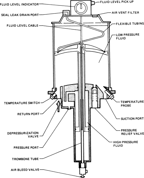
FIGURE 13-10 A reservoir pressurized by hydraulic pressure. (Lockheed-California Co.)
Another example of a hydraulic reservoir for a transport-category airplane is illustrated in Fig. 13-11. The reservoir shown is cylindrical in shape with a corrugated, perforated shield around the shell and has a fluid capacity of 2.5 U.S. gal [9.48 L]. A manifold, equipped with four main ports, a small pressure-line port, and a thermoswitch probe port, is welded to the bottom of the reservoir shell. The four main ports of the manifold are internally connected in tandem pairs, with both pairs opening into the supply fluid section of the reservoir. This configuration of ports makes possible either left or right installation of the reservoir by reversing the location of port connector unions and reducers. When connected in the system, one pair of ports delivers fluid to the suction ports of the engine-driven pump, the electrically driven auxiliary pump, and the ground service hand pump. One of the other pair of ports receives system return fluid, and the fourth port is equipped with a valve to drain the reservoir. A sight glass, located below the relief-and-bleed valve in the upper portion of the diaphragm-guide cylinder above the main portion of the reservoir, provides an indication of excessive accumulation of air in the reservoir. An instruction plate, mounted adjacent to the sight glass, and a pointer attached to the top of the relief-and-bleed valve above the sight glass, provide fluid-level instructions and direct fluid-level indications for system pressurized and depressurized conditions. A fluid-quantity transmitter, bracket, and actuating linkage, not shown in the illustration, is mounted on the inboard side of the reservoir cover. The lower end of the linkage is attached to the transmitter rotor, while the upper end is attached to the fluid-level pointer at the top of the relief-and-bleed valve. Fluid-level changes in the reservoir raise or lower the relief-and-bleed valve and pointer, thus extending or retracting the linkage and changing the position of the rotor in the fluid-quantity transmitter. The transmitter delivers a fluid-quantity signal to the fluid-quantity indicator in the flight compartment.

FIGURE 13-11 Hydraulic system reservoir.
The relief-and-bleed valve, located at the top of the diaphragm guide and above the sight glass, is provided to relieve excessive reservoir pressure and to bleed off accumulated system air. The relief valve is set to relieve pressure above 47 psi [324.07 kPa]. A drain line is attached to the relief-and-bleed valve to conduct excess pressure and bleed air overboard. An air breather is provided in the reservoir cover forward of the diaphragm guide. It allows the upper, ambient-air section of the reservoir to breathe air in and out as the reservoir diaphragm lowers and raises with pressurization of the hydraulic system and operation of the various subsystem actuators. A filter screen is provided in the breather to remove atmospheric impurities from the air that enter the upper portion of the reservoir.
Internally, the reservoir is equipped with a piston and diaphragm assembly that utilizes system pressure from the small pressure-line port to maintain a pressure head on the supply fluid. This pressure is from 28 to 30 psi [193 to 207 kPa] and is reduced from the system pressure of 3000 psi [20 685 kPa] by means of the difference in area between the piston and diaphragm. This difference ratio is approximately 100:1.
The application of force to the diaphragm can be understood by a study of the drawing of Fig. 13-11. Observe the arrows that indicate fluid pressure to the inside of the piston shaft and out through holes at the top. The pressure is then exerted downward between the barrel and the piston to the surface at the lower end of the barrel. The 3000-psi [20 685-kPa] pressure on this small area is balanced by the 28- to 30-psi [193- to 207-kPa] pressure against the bottom of the diaphragm, which has about 100 times the area at the bottom of the barrel. As fluid enters the reservoir, the diaphragm is forced upward inside the reservoir shell, thus carrying the diaphragm guide and barrel upward.
Integral Reservoirs
Integral reservoirs are combined with the hydraulic pump. These types of reservoirs are often found in small aircraft, where the compact arrangement of this type of mechanism is desirable. An example of this is the brake master cylinder used with many light-aircraft systems. As shown in Fig. 13-12, the upper portion of the assembly serves as the reservoir and the lower portion serves as the pump to operate the brake.

FIGURE 13-12 A reservoir in the same assembly as the fluid pump. (Cessna Aircraft Co.)
Reservoir for a Helicopter
A hydraulic reservoir for one model of a Sikorsky helicopter is shown in Fig. 13-13. This reservoir, referred to by the manufacturer as a hydraulic fluid tank, consists of an upper housing and a lower housing. The upper housing consists of a filler neck, an adapter, and a window sight gauge. The filler neck consists of a cap, which screws onto the neck, a scupper with an overboard drain, and a strainer, which is secured to the inside of the filler neck. The adapter, on top of the upper housing, consists of an adapter housing with a micronic filter element and a vent line that runs from the adapter fitting to the scupper. The lower housing incorporates a baffle plate, micronic filter element, drain plug, and relief valve with a differential cracking pressure of 6 to 8 psi [41.37 to 55.16 kPa]. Fluid returning to the tank circulates around the baffle plate and passes through the micronic filter element to the supply portion of the tank. If the filter element becomes clogged to the extent that a 6- to 8-psi [41.37 to 55.16-kPa] pressure builds up in the return portion of the tank, the relief valve opens to allow fluid to bypass the filter element and flow directly from the return portion of the tank to the supply portion. The tank (reservoir) may be drained by connecting a coupling and hose to the external supply coupling.

FIGURE 13-13 Hydraulic reservoir for a helicopter. (Sikorsky Aircraft Corp., Division of United Technologies Corp.)
HYDRAULIC FILTERS
Hydraulic filters are required to filter out any particles that may enter the hydraulic fluid. These particles may enter the system when it is being serviced or during wear of operating components. If these contaminants were allowed to remain in the circulating fluid, they could damage the seals and cylinder walls, causing internal leakage and prevent components such as check valves from seating properly. The number and location of filters in a hydraulic system depend on the specific model aircraft, but they are normally found at the inlet and outlet of the reservoir and the pump outlet. Commonly used filters are of the micronic type and porous metal type.
A micronic filter contains a treated paper element to trap particles in the fluid as the fluid flows through the element. The micron filters can be designed to filter out particles as small as 3 μm (A micrometer is equal to 0.0000394 in, or 0.0001 mm.) A micron filter assembly is shown in cutaway in Fig. 13-14. Also, a magnetic-type element that will attract metal particles can be used in conjunction with the paper element to make a dual-element type filter.

FIGURE 13-14 Hydraulic filter.
Porous metal filters are composed of metal particles joined together by a sintering process. These filters can trap particles as small as 5 μm in size.
Most hydraulic filter assemblies are located in the pressure and return lines. In-line filters are generally constructed much like the one illustrated in Fig. 13-15. The filter illustrated consists of a head assembly, a bowl assembly, and a 15-μm paper filter element. The head assembly contains the fluid line connections and a shutoff valve to facilitate replacement of the filter element. A bypass valve in the filter prevents the system from becoming inoperative should the filter become clogged. Many filters incorporate a “pop-out” differential pressure indicator, such as the one shown in Fig. 13-15, to allow ready identification of a clogged filter. This pop-out indicator may also be electrically connected to the cockpit to provide notification of a clogged filter. The bowl assembly is mounted on the bottom of the head assembly and is sealed with an O ring. This is the housing that contains the filter element.
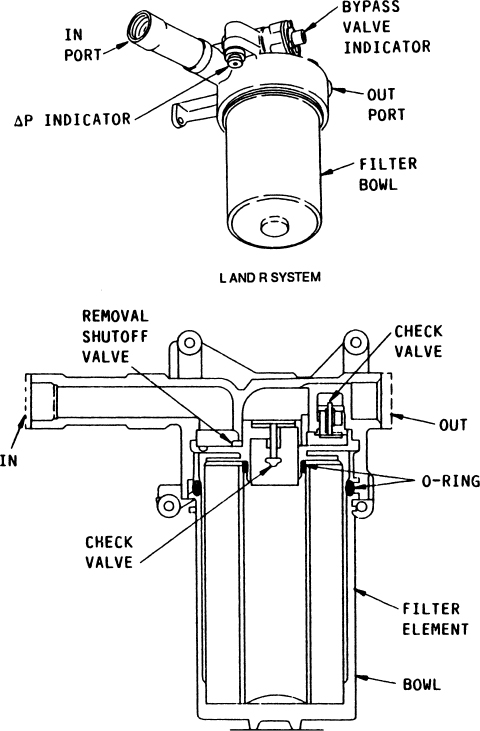
FIGURE 13-15 Hydraulic filter assembly.
When filters are serviced, all pressure should be removed from the hydraulic system. When removing the bowl and element, care should be taken to prevent prolonged contact of the fluid with the aircraft, clothing, or skin—especially if a phosphate ester fluid is being used. If a micronic element is used, this is replaced with a new element; the old element can be opened to check for contamination. If the contamination indicator pin has popped out, then the fluid and filters downstream from the filter must be checked for contamination and the system flushed if required. If a porous metal element is used, this should be cleaned or replaced in accordance with the appropriate service manual.
Heat Exchangers
Because of the high pressures involved in many hydraulic systems and the high rates of fluid flow, the hydraulic fluid becomes heated as the subsystems are operated. For this reason it is often necessary to provide cooling for the fluid. The heat exchanger, shown in Fig. 13-16, is a heat radiator similar in design and construction to an oil cooler for an engine. Note that the heat exchanger is equipped with a temperature-operated bypass valve to increase the fluid flow through the cooling element as temperature rises.

FIGURE 13-16 Heat-exchanger cooling unit.
Heat exchangers are often installed in the pumpcase drain return lines to cool the hydraulic fluid before it enters the reservoir. Cooling of the fluid may be provided by different means. The heat exchangers for some aircraft are installed in fuel cells and cool the hydraulic fluid by transferring the heat of the fluid to the fuel. Other aircraft utilize air to cool the fluid, with ram air used in flight and engine bleed air used when the airplane is on the ground.
The temperature-operated bypass valve in the hydraulic cooler fluid inlet controls the volume of return fluid circulating through the fluid cooler. As fluid temperatures rise, the bypass valve starts to close, porting return fluid through the hydraulic cooler. At high fluid temperatures, the bypass valve is fully closed, porting all return fluid through the cooler.
HYDRAULIC PUMPS
Hydraulic pumps are designed to provide fluid flow and are made in many different designs, from simple hand pumps to very complex, multiple-piston, variable-displacement pumps.
Hand Pumps
A diagram of a single-acting hand pump is shown in Fig. 13-17. This diagram illustrates the basic principle of a piston pump. When the handle is moved toward the left, the piston movement creates a low-pressure condition and draws fluid from the reservoir through the check valve and into the cylinder. Then when the handle is moved toward the right, the piston forces the fluid out through the discharge check valve. The check valves allow the fluid to flow only in one direction, as shown by the arrows.

FIGURE 13-17 Single-acting hand pump.
A double-acting piston-displacement type of hand pump is shown in the drawing of Fig. 13-18. The IN port from the reservoir is connected to the center of the cylinder, where there is a space between the two pistons and surrounding the shaft connecting the pistons. In each piston is a check valve (nos. 1 and 2) and a passage that allows fluid to flow from the center chamber to the spaces at each end of the dual-piston assembly. When the pump handle is moved to the right, the piston assembly moves to the left, forcing fluid out though check valve 3 into the system. The check valve in the left-hand piston is held closed by fluid and spring pressures. As the piston assembly moves to the left, a low-pressure area is created in the chamber in the right end of the cylinder, and this causes fluid to flow through check valve 1 into the chamber. Check valve 4 is held in the closed position by spring and fluid pressure. When the pump handle is moved to the left, the piston assembly moves to the right and the fluid is forced out of the right-hand chamber through check valve 4 into the system. Note that a fluid passage connects the outlet chambers at each end of the cylinder.
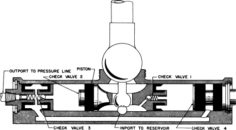
FIGURE 13-18 A double-acting, piston-displacement pump.
Gear-Type Pump
A gear-type pump is shown in the drawing of Fig. 13-19. This pump is classed as a positive-displacement pump because each revolution of the pump will deliver a given volume of fluid, provided the pump is not worn and no leakage occurs. One of the two gears is driven by the power source, which could be an engine drive or an electric-motor drive. The other gear is meshed with and driven by the first gear. As the gears rotate in the direction shown, fluid enters the IN port to the gears, where it is trapped between the gear teeth and carried around the pump case to the OUT port. The fluid cannot flow between the gears because of their closely meshed design; therefore, it is forced out through the OUT port.

FIGURE 13-19 A gear-type pump.
Vane-Type Pump
The vane-type pump is also classed as a positive-displacement pump because of its positive action in moving fluid. This pump is illustrated in the drawing of Fig. 13-20 and consists of a slotted rotor located off-center within the cylinder of the pump body with rectangular vanes free to move radially in each slot. As the rotor turns, the vanes are caused to move outward by centrifugal force and contact the smooth inner surface of the casing. Since the rotor is eccentric with respect to the casing, the vanes form chambers that increase and decrease in volume as the rotor turns. The inlet side of the pump is integral with the side of the casing in which the chambers are increasing in volume. Thus the fluid is caused to enter the chambers because of the low-pressure area created by the expanding chambers. The fluid is carried around the casing to the point where the chambers begin to contract, and this section of the casing is connected to the output port of the pump. The contraction of the chambers forces the fluid into the outlet port and system.
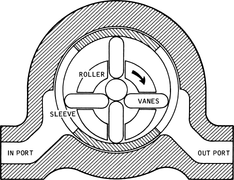
FIGURE 13-20 A vane-type pump.
Gerotor Pump
A gerotor pump, shown in Fig. 13-21, consists of a housing containing an eccentric-shaped stationary liner, an internal gear rotor having five wide teeth of short height, a spur driving gear having four narrow teeth, and a pump cover, which contains two crescent-shaped openings. One opening extends into an inlet port and the other connects to an outlet port. In Fig. 13-21 the pump cover is shown with the inner surface visible to display the inlet and outlet openings inside the pump. When the cover is turned over, the inlet is on the left and the outlet is on the right.
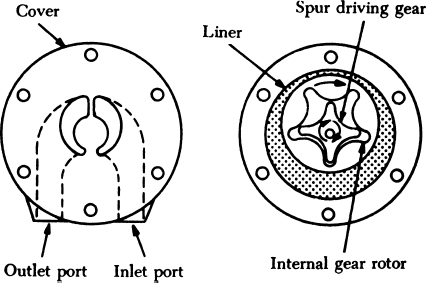
FIGURE 13-21 Gerotor-type power pump.
During operation, the gears turn clockwise. As the cavities move from the bottom of the gear to the top of the gear, they increase in volume, resulting in a vacuum being created in this area. As this cavity passes the inlet port, fluid is drawn into the cavity. As this cavity moves to the right side of the pump, the size of the cavity is decreased and fluid is forced out of the pump via the outlet port.
Multiple-Piston Pump
One of the most widely used hydraulic pumps for modern aircraft is the axial multiple-piston pump. This type of pump is shown in Fig. 13-22. The pump consists of a drive shaft to which the pistons are attached by means of ball sockets, a cylinder block into which the pistons are inserted, and a stationary valving surface, which fits closely against one end of the cylinder block. The drive shaft is connected to the cylinder block by means of a universal link to rotate the cylinder block with the drive shaft. The axis of rotation for the cylinder block is at an angle to the axis of rotation of the drive shaft; therefore, the pistons are caused to move in and out of the cylinders as rotation occurs. The pistons on one side of the cylinder block are moving outward, thus increasing the volume of the cylinder spaces; on the other side of the cylinder block the pistons are moving inward. The valve plate is made with two slots such that one slot is bearing against the side of the cylinder block on which the pistons are moving away from the valving surface; the other slot is bearing against the side on which the pistons are moving toward the valving surface. The slots in the valving surface are connected to inlet and outlet chambers to provide fluid feed to the pistons on the inlet side and an outlet for the pressure fluid on the other side. As the drive shaft rotates, the pistons on one side of the cylinder block draw fluid through the valving surface slot, and the pistons on the other side force the fluid through the outlet slot.

FIGURE 13-22 Cutaway drawing of an axial piston pump.
A cutaway illustration of a fixed-delivery pump manufactured by Sperry Vickers, Division of Sperry Rand Corp., is shown in Fig. 13-23. Fixed delivery means that the pump will normally deliver a fixed amount of fluid at a given number of revolutions per minute. A variable-delivery pump is shown in Fig. 13-24. This pump is designed so the alignment of the rotational axis of the cylinder block can be changed as desired to vary the volume of fluid being delivered at a given rpm. By changing the angle of the rotational axis, the stroke of the pistons is decreased or increased; therefore, the volume of fluid pumped during each stroke of the pistons is reduced or increased. If the axis of the cylinder block is parallel to the axis of the drive shaft, no fluid will be delivered, because there will be no movement of the pistons within their respective cylinders.

FIGURE 13-23 A fixed-delivery piston pump. (Sperry Vickers Div., Sperry Rand Corp.)

FIGURE 13-24 A variable-delivery pump. (Sperry Vickers Div., Sperry Rand Corp.)
In-Line Variable Delivery Pump
Transport aircraft use in-line variable delivery pumps for their hydraulic systems. The components of a variable delivery piston pump are illustrated in Fig. 13-25. These pumps could be engine driven, electrical driven, or air driven. A variable-delivery pump adjusts fluid output depending on system demands. The pump output is changed automatically by a pump compensator within the pump. The first stage of the pump consists of a centrifugal pump which boosts the pressure before the fluid will enter the second stage piston pump. Figure 13-26 is a schematic of a typical pump used on a large transport aircraft and Fig. 13-27 shows the control function of this pump including the depressurization solenoid and blocking valve. The control function is the bottom-left portion of Fig. 13-26.

FIGURE 13-25 A cam-type piston pump. (Sperry Vickers Div., Sperry Rand Corp.)

FIGURE 13-26 In-line variable delivery pump schematic.
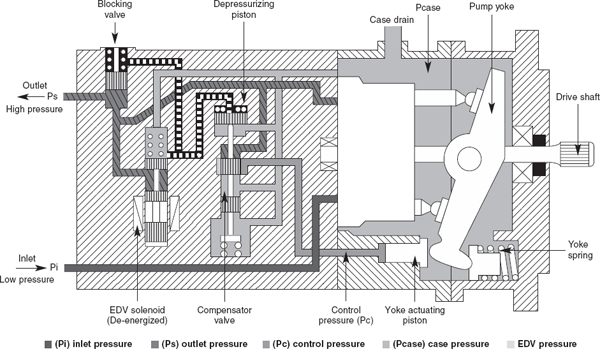
FIGURE 13-27 Variable delivery pump control.
An in-line variable delivery piston pump operates on the same principle as the multiple-piston pumps described in the foregoing section: however, the drive shaft is parallel to the pistons. The movement of the pistons necessary to create a pumping action is caused by a shoe-bearing plate in the yoke assembly. As the cylinder block rotates the piston shoe continues following the yoke-bearing surface and it pushes the pistons into the cylinders, causing them to eject the fluid into the out port. The pistons on the descending portion of the yoke can draw fluid from the in port of the pump. The angle of the yoke as established by the compensator valve determines the amount of fluid expelled during each stroke of the pistons, thus providing the variable delivery required. Each piston completes this cycle on each revolution of the drive shaft, providing a continuous, non-pulsating flow of fluid to the system. Check valves are located at the outlet of the each piston to prevent pressurized fluid from flowing back into the cylinders as the pistons move back in the cylinders. Internal leakage keeps the pump housing filled with fluid for lubrication of rotating parts and cooling. The leakage is returned to the return side of the hydraulic system through a case drain port. The case valve relief valve protects the pump against excessive case pressure, relieving it to the pump inlet.
The control mechanism for the variable-delivery pump is shown in Fig. 13-27. Remember that the output of this type of pump is determined by the angle of the shoe-bearing plate in the yoke assembly which produces a reciprocating action of the piston pumps. The yoke angle is changed by pressure on the yoke-actuating piston. Below system pressure of 2850 psi the compensator valve is in the up position and no high pressure can flow to the yoke actuator piston. In this position the pump delivers maximum flow. When the pressure increases above 2850 psi the compensator valve cracks open (valve moves down) and high pressure can act on the yoke actuator piston which reduces the yoke angle and as a result the output of the pump is decreased. When system pressure reaches 3025 psi the compensator valve is all the way open and high pressure acting on the yoke actuating piston will move the yoke to the zero position. The output of the pump decreases to zero and the unit pumps only its own internal leakage. The pump will provide a variable flow depending on the system pressure between 2850 and 3025 psi. The higher the pressure, the lower the flow.
Depressurized Mode
The pump in Fig. 13-26 is outfitted with a depressurization and blocking feature. This depressurization and blocking feature can be used to reduce the load on the engine during start-up and, in a multiple pump system, to isolate one pump for check-out purposes. When the solenoid valve is energized, the EDV solenoid valve will move up against the spring force and the outlet fluid is ported to the piston on the top of the compensator valve (depressurizing piston). The high-pressure fluid pushes the compensator valve spool down beyond its normal metering position. High pressure can flow directly to the yoke actuator valve which places the yoke in its zero position and reduces the output of the pump to zero flow. At the same time outlet fluid is also ported to the blocking valve spring chamber, which equalizes pressure on both sides of its plunger. The blocking valve closes due to the force of the blocking valve spring and isolates the pump from the external hydraulic system.
Ram Air Turbines
A method used on many turbine transport-category aircraft to power a pump in the event of engine and electrical system failure is the utilization of a ram air turbine (RAT), such as the one shown in Fig. 13-28. The RAT installation typically consists of an air turbine, a speed-governing device, and a variable-volume pump. The RAT can usually be deployed manually or may automatically deploy in the event of engine failure.

FIGURE 13-28 A ram air turbine in the extended position. (Lockhead-California Co.)
PRESSURE-CONTROL DEVICES
Numerous devices have been designed to control pressure in hydraulic systems; among these are pressure switches, pressure regulators, relief valves, and pressure-reducing valves.
Pressure Switches
Electrically operated pressure switches are used in hydraulic systems with electrically driven pumps to maintain system pressure within set limits. The pressure switch is set to open the electrical circuit to the pump motor when system pressure builds up to correct values, causing the pump to stop. As pressure drops to a lower value, the pressure switch closes the circuit to start the pump operating again. Pressure switches are also used in hydraulic systems to control the operation of warning and protective devices. The switch may turn on a light to warn the pilot of insufficient pressure, or it may turn off a pump to avoid exhausting reservoir fluid through a broken line. Pressure switches come in various types. For example, there are the Bourdon-tube type, the piston type, and the diaphragm type.
The Bourdgn-tube type pressure switch illustrated in Fig. 13-29 is frequently used to control pressure within a hydraulic system. The flexible steel finger attached to the small end of the Bourdon tube moves outward as the tube (a) begins to uncoil. This finger presses against the toggle plate (b) until the desired system pressure is reached, at which time it will cause the toggle to pivot rapidly, thereby opening the contact points and breaking the electrical circuit.

FIGURE 13-29 Bourdon tube pressure switch.
Pressure Regulators
A pressure regulator is designed to maintain a certain range of pressures within a hydraulic system. Usually the pressure regulator is designed to relieve the pressure on the pressure pump when it is not needed for operating a unit in the system. Some pressure regulators are also called unloading valves because they unload the pump when hydraulic pressure is not required for operation of landing gear, flaps, or other subsystems. Continuous pressure on the pump increases wear and the possibility of failure.
A pressure regulator that is also an unloading valve is illustrated in Fig. 13-30. In this view, the unit is operating to supply fluid for charging an accumulator (hydraulic-pressure storage chamber) and to supply fluid pressure for operating units in the system. Fluid flows into port B and out of port A to the system. The check valve is off its seat because of the fluid pressure being exerted by the pressure pump. When the pressure in the accumulator builds up to the maximum level for the system, the same pressure is exerted in chamber F, Fig. 13-31. This pressure moves the plunger (piston) (3) upward to raise the pilot valve (2) against the pressure of the spring (1). In Fig. 13-30, observe that fluid pressure is applied to one of the pilot-valve chambers through a passage from the inlet line, around an annular groove surrounding the unloading valve [(4) in Fig. 13-31], and to the pilot valve. As the pilot valve is raised, this pressure is ported and directed through a passage to the left end of the directional spool (5). This spool moves to the right and causes hydraulic pressure to be directed against the right end of the unloading spool, thus moving it to the left. This permits the main flow of fluid to go from port B, through passage E, and out the return port C. Under this condition the power pump is unloaded because the fluid has free flow back to the reservoir. The regulator is said to be “kicked-out” in this position. The check valve has seated because of spring pressure and holds the pressure locked in the system. In the drawings, port D is the “bleed-off” port, which permits fluid from the chambers at the ends of the directional spool and unloading spool to escape and allow movement of the spools as required.

FIGURE 13-30 An unloading-type pressure regulator.
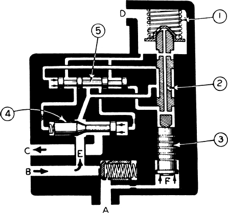
FIGURE 13-31 Unloading valve in the “kicked-out” position.
When a subsystem is operated and fluid pressure in the pressurized part of the system drops to a pre-determined level, the pilot valve and plunger will move back to the lower position, directing pressure against the right end of the directional spool, as shown in Fig. 13-32. The directional spool moves to the left and causes fluid pressure to be directed to the left end of the unloading spool, moving it to the right and blocking the return line. Pump pressure then builds up and opens the check valve (bullet valve) to allow fluid flow to the operating system through port A. This position is often referred to as “kicked-in.”
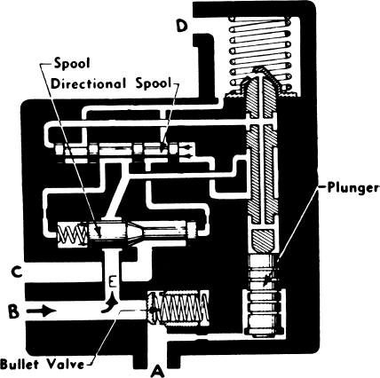
FIGURE 13-32 Moving to the “kicked-in” position.
Another type of pressure regulator that serves a purpose similar to the one just described is the balanced type. A drawing of this regulator in the kicked-in position is shown in Fig. 13-33. In this drawing, the bypass valve E is held closed by spring pressure and system pressure. Fluid from the power pump enters at port F, and the pressure forces the check valve G off its seat and allows the fluid to flow out port H to the accumulator and the system. When the system-operating requirements are met, the pressure continues to build up from the pump and throughout the area in operation. This pressure bears against the poppet valve I and also increases above the piston N because of the sensing line O. The piston N has greater area than the poppet valve I; therefore, the force downward increases faster than the force upward. At a certain point the force downward becomes equal to the force upward and the valve is then said to be in the balanced condition. As pressure continues to increase, the downward force becomes greater than the upward force and the rod M moves downward against the force of the spring L. The hollow piston rod M moves downward and contacts the poppet valve, thus forcing it off its seat. Pressure fluid then can flow through the passage K to act against the directional valve C, which pushes the bypass valve E off its seat. When this occurs, pressure fluid entering port F can flow out through port D to the reservoir, and the pressure entering port F drops to the free-flow level. Check valve G is then immediately seated by spring pressure to trap the high pressure in the system. This is the kicked-out position, as illustrated in Fig. 13-34.
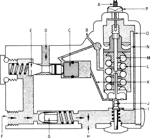
FIGURE 13-33 Bendix balanced-type regulator.

FIGURE 13-34 Bendix pressure regulator in the “kicked-out” position.
For proper operation, the regulator should remain in the kicked-out position until the pressure in the system has dropped to the lower operating level. This it will do, because the pressure for the initial kick-out was great enough to overcome the force of the spring L and the pressure against the poppet I. Since the poppet has been lifted from its seat, the only force necessary to keep the valve in the kicked-out position is that on the piston N acting against the spring L.
Therefore, the pressure in the system will drop substantially before the valve kicks in again.
The kick-out pressure of the valve is adjusted by turning the adjusting screw A. This changes the effect length of the rod below the piston and changes the amount of force necessary to bring about the kicked-out condition.
Relief Valve
A relief valve is comparatively simple in construction, and its function is to limit the maximum pressure that can be developed in a hydraulic system. Thus it acts as a safety valve similar in function to one that would be found in an air- or steam-pressure system. During operation, the relief valve remains closed unless the system pressure exceeds that for which the valve is adjusted. At this time the valve opens and allows the fluid to flow through a return line to the reservoir.
A drawing to illustrate the construction of a relief valve is shown in Fig. 13-35. During normal operation, the valve is on its seat and fluid flows from the IN port to the OUT port without restriction. As the pressure on the line increases to a level above that for which the valve spring is adjusted, the valve lifts off its seat and the fluid then flows through the valve and out the return line. The pressure at which the relief valve lifts is called the cracking pressure. The design of the valve must be such that it will not rapidly open and close and cause chattering, since this would damage the system. Relief valves are used to control maximum system pressure and to control pressure in various parts of the subsystems. For example, a relief valve, called a wing-flap overload valve, is often placed in the DOWN line of the wing-flap subsystem to prevent lowering of the flaps at too high an airspeed. The pressure in the DOWN line will rise above a specified level because of air pressure against the wing flaps if the airspeed is too great. The wing-flap overload valve will then open and allow excess pressure to be relieved, thus causing the down movement of the flaps to stop.

FIGURE 13-35 Construction of a relief valve.
When several relief valves are incorporated in a hydraulic system, they should be adjusted in a sequence that will permit each valve to reach its operating pressure. Thus, the highest-pressure valves should be adjusted first; the others are then adjusted in the order of descending pressure values.
Thermal Relief Valves
A thermal relief valve is similar to a regular system relief valve; however, such valves are installed in parts of the hydraulic system where fluid pressure is trapped and may need to be relieved because of the increase caused by higher temperatures. During the flight of an airplane, it is quite likely that fluid in many of the hydraulic lines will be at a low temperature. When the airplane lands, this cold fluid will be trapped in the landing-gear system, the flap system, and other systems because selector valves are in the neutral, or OFF, position. The fluid-temperature increase due to warm air on the ground results in fluid expansion and could cause damage unless thermal relief valves are incorporated in the systems. Thermal relief valves are adjusted to pressures that are above those required for the operation of the systems; therefore, they do not interfere with normal operation.
PRESSURE-REDUCING VALVES
Requirements of some parts of the system may demand that the designer utilize a lower pressure than the normal system operating pressure. It may be desirable to have a reduced operating pressure to prevent overloading some structures. A pressure-reducing valve will fill this need. The proper valve will reduce system pressure to the desired level; it will also relieve thermal expansion in the section of the system that it isolates. Figure 13-36 shows how a pressure-reducing valve is positioned to bring about a lower pressure for operation of the actuating cylinder.
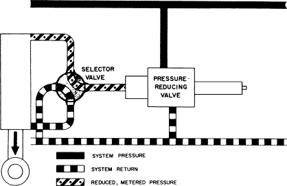
FIGURE 13-36 Typical pressure-reducing valve installation.
The pressure-reducing valve illustrated in Fig. 13-37 has three ports. One is connected to system pressure, one is connected to the system return line, and the third is the reduced-pressure port. The pressure-reducing spring (A) is holding the reservoir return valve (B) and the poppet (D) to the left. Fluid under system pressure enters the system pressure port (C), where it passes around the unseated poppet and out the reduced-pressure port (E). As the fluid going out port (E) builds pressure, hydraulic force is transmitted back through the hollow poppet (D) and exerts a force on the reservoir return valve (B). When this force overcomes spring force, the reservoir return valve is pushed to the right, allowing the poppet spring (F) to seat the poppet. This prevents system fluid from going out the reduced-pressure port (E) to build up a further pressure. The inlet pressure (C) has no effect on the poppet itself because the areas on each end of the poppet exposed to the pressure are the same; therefore, the forces exerted on the poppet are balanced. The pressure exerts an unbalanced force only on the area of the reservoir return valve (B).
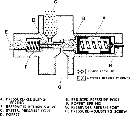
FIGURE 13-37 Pressure-reducing valve.
In actual operation, this pressure-reducing valve will close when the desired pressure is reached. When the actuator is in operation under reduced pressure, the valve will vary its opening to meter the fluid at the speed required to maintain the desired pressure.
Another type of pressure-reducing valve is a debooster valve used in an aircraft brake system to reduce system pressure; in addition to reducing pressure it will provide for a higher volume of fluid flow to the brakes for rapid application of braking forces.
A review of two basic formulas, F = P × A and V = A × L, will assist in providing a better understanding of deboosters. To determine the value of a force produced by pressure that acts on a given area, the formula F = P × A is used, where F is the total force, P is the value of the pressure expressed in pounds per square inch (psi), and A is the area of the surface exposed to the pressure. To find the volume of fluid required to move a piston within a cylinder or the amount exhausted, the formula V = A × L is used, where V equals the total volume delivered per stroke expressed in cubic units (usually cubic inches), A is equal to the surface area of the piston, expressed in square inches, and L is equal to the length of the stroke or the distance through which the piston moves as it discharges fluid.
A debooster valve operates by the differential area of two pistons. If a small-area piston is connected by a rod to a large-area piston, the two pistons will be capable of developing pressure in inverse proportion to their areas. Figure 13-38 illustrates the debooster principle. If the area of the small piston is 1 in2 [6.45 cm2] and the area of the large piston is 4 in2 [25.8 cm2], the large piston can transmit a pressure of only one-quarter that of the small piston. When 1000 psi [6895 kPa] is applied to the small piston, a force of 1000 lb [4448 N] will be exerted through the rod to the large piston. Since the large piston has a 4-in2 [25.8-cm2] area, a force of 1000 lb [4448 N] will develop a pressure of only 250 psi [1723.8 kPa] in the large cylinder.
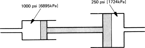
FIGURE 13-38 Principle of the debooster.
A debooster consists of two pistons of different sizes fastened together in a cylinder housing machined for each piston, as illustrated in Fig. 13-39. Movement of one piston causes the other also to move. The main feature of the debooster is the piston, which has two different areas. The upper area (N) and the lower area (H) will have a given ratio. The extra fluid that is discharged will cause rapid application of brakes. The outlet port (D) and line must be larger than the inlet port to accommodate the extra flow.

FIGURE 13-39 Typical debooster.
ACCUMULATORS
An accumulator is basically a chamber for storing hydraulic fluid under pressure. It can serve one or more purposes. It dampens pressure surges caused by the operation of an actuator. It can aid or supplement the system pump when several units are operating at the same time and the demand is beyond the pump’s capacity. An accumulator can also store power for limited operation of a component if the pump is not operating. Finally, it can supply fluid under pressure to make up for small system leaks that would cause the system to cycle continuously between high and low pressure.
Accumulators are divided into three types according to the means used to separate the air and fluid chambers. The three types are diaphragm, bladder, and piston.
Diaphragm-Type Accumulator
Since hydraulic fluid is incompressible, practically speaking, some means is necessary to provide sustained pressure on the fluid if effective energy storage is to be maintained. For this purpose compressed air or an inert gas is used. The usual construction of the accumulator is such that a volume of compressed air is applied to a volume of fluid so the fluid will continue to be under pressure. The fluid and air are separated by a diaphragm so air cannot enter the hydraulic system.
The diaphragm-type accumulator consists of a metal sphere separated by a synthetic-rubber diaphragm, as shown in Fig. 13-40. The sphere is constructed in two parts, which are joined by means of screw threads. At the bottom of the sphere is an air valve, such as a Schrader valve, and at the top is a fitting for the hydraulic line. A screen is placed at the fluid outlet inside the sphere to prevent the diaphragm from being pressed into the fluid outlet.

FIGURE 13-40 A diaphragm-type accumulator.
During operation of the accumulator, the air chamber is preloaded, or charged, with air pressure (approximately one-third maximum system pressure). As soon as a very small amount of fluid is forced into the fluid side of the accumulator, the system pressure gauge will show the pressure in the air chamber. This provides a means for checking the air charge (pressure) in the accumulator. If the system is inactive and the main pressure gauge shows zero pressure, a few strokes of the hand pump will cause the pressure gauge to rise suddenly to the charge pressure in the accumulator. The accumulator charge can also be checked by the reverse method. For example, if the system gauge shows a pressure of 1500 psi [10 342.5 kPa] when the system pump is not operating and the brakes are depressed and released a number of times, the pressure will decrease to the accumulator charge pressure and then will suddenly fall to zero.
It should be noted that some aircraft hydraulic systems monitor the hydraulic pressure by indicating the pressure on the air side of the accumulator. When the system has no hydraulic pressure, the gauge for the system indicates the accumulator air pressure. As soon as the hydraulic pressure is greater than the air charge, the air is compressed to the value of the hydraulic system pressure.
Bladder-Type Accumulator
The bladder-type accumulator usually consists of a metal sphere in which a bladder is installed to separate the air and the hydraulic fluid. The bladder serves as the air chamber, and the space outside the bladder contains the hydraulic fluid. The construction of a bladder-type accumulator is shown in Fig. 13-41. The air valve is at the bottom of the sphere; the fluid port is at the top. Initially, the bladder is charged with air pressure, as specified in the aircraft manual. When fluid is forced into the accumulator, the bladder collapses to the extent necessary to make space for the fluid, depending upon the fluid pressure.
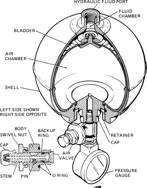
FIGURE 13-41 System accumulator.
Piston-Type Accumulator
Many modern hydraulic systems employ piston-type accumulators because they require less space than an equivalent spherical accumulator. A piston-type accumulator is shown in Fig. 13-42. Note that this unit consists of a cylinder with a free piston inside to separate the air from the hydraulic fluid. The piston is equipped with seals that effectively prevent the air from leaking into the fluid chamber and vice versa.

FIGURE 13-42 A piston-type accumulator.
Servicing Accumulators
Accumulators should be checked for proper air charge at regular intervals. With no hydraulic pressure on the system, the accumulator should have a charge of between one-third and one-half of the system’s operating hydraulic pressure. Specific values are given by the aircraft manufacturer. Many accumulators are equipped with permanent pressure gauges, but some require the use of a hand-held gauge.
If the accumulator must be charged, hydraulic pressure is removed from the system before the accumulator is charged. Nitrogen is the gas commonly used, but dry air may be used in some cases.
Removal and Installation of Accumulators
Great care must be exercised in the servicing and repair of hydraulic systems. This is particularly true of the high-pressure systems, which operate at pressures in excess of 3000 psi [20 685 kPa]. Before an accumulator or any other unit is removed, the technician must make certain that all the pressure in the system has been relieved. This is accomplished by operating one of the subsystems until all pressure is gone and the main pressure gauge reads zero pressure. The air pressure in the accumulator is reduced to zero by opening the air valve in accordance with the manufacturer’s instructions. The accumulator can then be disconnected; however, provision should be made for fluid drainage. If the system contains a synthetic, fire-resistant fluid, such as Skydrol, the fluid must not be permitted to drain onto painted areas or other parts where the fluid can cause damage.
The installation of an accumulator is usually the reverse of removal. The air chamber of the accumulator is downward when the accumulator is installed. Sometimes the air charge is placed in the accumulator before installation. In any event, the manufacturer’s instructions should be followed. Particular care must be taken to see that all seals, valves, and fittings are of the proper type for the fluid being used in the system.
If hydraulic fluid is found in the air chamber of an accumulator, there is a leak between the two chambers. In such cases, the accumulator must be removed and repaired.
SELECTOR VALVES
Selector valves are used to direct the flow of hydraulic fluid to or from a component and achieve the desired operation. These valves fall into one of four general types: rotary, poppet, spool or piston, and open-center-system selector valves. The valves may be positioned by the pilot directly, by an electrical or electronic control, by hydraulic pressure, or by pneumatic pressure.
Rotary Valve
When a rotary four-way valve is in the position shown in Fig. 13-43(a), the fluid will flow from the valve at the top port and will cause the actuating cylinder to be extended. When the valve is rotated 90°, as in Fig. 13-43(b), the fluid to and from the actuating cylinder will be in the opposite direction, and the cylinder will retract.
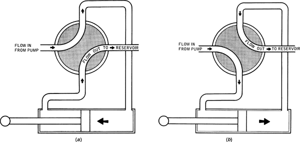
FIGURE 13-43 A rotary four-way valve.
Poppet Valve
Another type of flow-control valve is shown in Fig. 13-44. The valve is shown operating a landing-gear system. This type of valve can be used to operate an actuator for any aircraft system. In this valve assembly, individual poppet valves are used to open and close the ports to change the direction of fluid flow. The valves are operated by cam lobes on cam rod C. Fluid enters the valve through line P from the pressure pump, and with the gear control in the DOWN position, it passes through open valve 4 and on to the actuating cylinder. As the piston moves to the left, fluid from the left end of the actuating cylinder flows through passage B and open valve 1 to the return chamber and back to the reservoir through the return line R.

FIGURE 13-44 Poppet-type four-way valve.
If the gear-control handle is placed in the neutral position, cam lobe 8 will open poppet valve 3, and cam lobes 6 and 9 will close poppet valves 1 and 4, assuming that the poppets are equipped with springs to keep them closed unless they are lifted by a cam lobe. When poppet valve 3 is open, fluid flow will pass from the pressure chamber PC to the neutral chamber NC and from there to the return manifold, thus permitting the fluid to flow freely and thereby reducing the load on the pressure pump. In the neutral position, valves 2 and 5 are closed because cam lobes 7 and 10 are not yet in position to open them.
When the gear-control handle is placed in the UP position, valves 2 and 5 will be open and the others will be closed. Fluid will therefore flow through poppet valve 2 and out the passage B to the left end of the actuating cylinder. The piston will move to the right and force fluid through passage A and poppet valve 5 to the return chamber and return line to the reservoir.
Some poppet valve assemblies are arranged with valves in a radial position, and they are opened and closed by means of a rotary cam unit. The results are the same in any case. Poppet valves are also manufactured with electric controls, and the individual valves are opened and closed by means of solenoids.
Spool or Piston Selector Valves
A schematic drawing of a typical spool-type selector valve is shown in Fig. 13-45. The three positions of the valve are shown to illustrate the passages for fluid in the OFF, DOWN, and UP positions. Note that there is no fluid flow when the valve is in the OFF position; therefore, the valve must be used in a system where a pressure regulator or variable delivery pump is employed. Otherwise a high pressure would build up and cause excessive wear or other damage to the pressure pump. The use of this valve is not restricted to landing-gear systems.
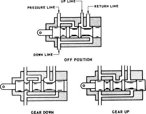
FIGURE 13-45 A spool-type selector valve.
A simple piston-type selector valve is illustrated in the drawing of Fig. 13-46. In the first drawing, the valve is in the OFF position, and fluid flow is blocked because both port A and port B are blocked by the piston. In the second view, port A is open to allow fluid to flow out to an actuating cylinder; the return flow from the cylinder enters port B and flows out port B to the reservoir. The third view shows the reverse position where fluid flows out port B and back through port A. The center of the piston rod is provided with a drilled passage, which allows the return fluid to flow to the right and out through the return port R.

FIGURE 13-46 A piston-type selector valve.
Open-Center-System Selector Valve
The details of an open-center hydraulic system are given later in this chapter; however, it is important to understand that in this type of system, all selector valves are connected in series to a common fluid supply and return line. The valve shown in Fig. 13-44 is suitable for an open-center system.
Like other forms of selector valves, the open-center selector valve provides a means of directing hydraulic fluid under pressure to one end of an actuating cylinder and of simultaneously directing fluid from the opposite end of the actuating cylinder to the return line. The advantage is that the valve automatically returns to neutral when the actuating cylinder reaches the end of its stroke. The fluid output of the power pump is directed through this valve to the reservoir when the valve is in neutral position.
The valve illustrated in Fig. 13-47 consists of a housing that has four ports, a piston, two metering pins, two check valves, and a spring-loaded roller and cam-arrangement that is attached to the end of the piston. The roller and cam arrangement is designed to hold the piston in either the operating position after it has been engaged or the neutral position.

FIGURE 13-47 An open-center system selector value.
In the illustration, the sliding piston is in one of the two operating positions. The sliding piston has been moved manually to the right and is held in position by the spring-loaded cam mechanism, Fluid under pressure flows from the inlet port A through port D to one side of the hydraulic actuating piston, moving the actuating piston to its fully extended or retracted position. Fluid returning from the opposite side of the piston enters the selector valve at B and discharges through the return port C to the reservoir.
Figure 13-48 shows the same valve in the neutral position, where it is held by the lever and cam arrangement. The position of the lever, which rotates about the shaft, is determined by the position of the roller, which rolls on the cam. In the neutral position, the inlet port A is connected directly to the return port C, thus allowing the fluid to flow freely through the valve.

FIGURE 13-48 Open-center selector valve in the neutral position.
The valve is automatically returned to the neutral position by action of fluid pressure, which opens the relief valve and admits fluid pressure to the end of the piston. This pressure forces the valve piston back to the neutral position. The action takes place for either position of the valve.
Electrohydraulic Servo Control Valve
Electrohydraulic servo control (EHSC) valves are used extensively in transport aircraft that use a fly-by-wire flight control system. Hydraulic valves are operated without a mechanical connection. These types of valves use electrical solenoids to operate the control valve. In Fig. 13-49 both solenoids are not energized and hydraulic fluid pressure can flow past the pilot valves and apply pressure on both sides of the main spool valve. Because the areas of the spool valve ends and the springs are identical the main spool valve remains in the neutral position and the cylinder ports at the bottom of the valve are connected with the return line and the pressure line is blocked. This type of valve is called a closed center valve.
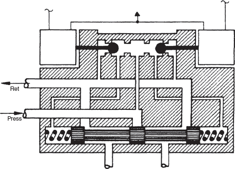
FIGURE 13-49 Solenoid-operated servo valve.
In Fig. 13-50 the right solenoid is energized and the right pilot valve will move to the left and will block fluid pressure from going to the right side of the main spool valve and will connect the right side of the main spool valve with the return line. The main spool valve will move to the right because the pressure on the left side of the main spool valve is now higher than on the right side. When the main spool valve moves to the right the pressure line will be connected with the left cylinder port. When the right solenoid is de-energized the pressure will again be allowed to go to the right side of the main spool valve and the hydraulic pressure on both sides will be equal and the main spool valve moves to the neutral position because of spring pressure.

FIGURE 13-50 Servo control valve with one solenoid energized.
AUTOMATIC-OPERATING CONTROL VALVES
An automatic-operating control valve is one that is designed to operate without being positioned or activated by any force outside of the hydraulic fluid pressure or flow. These valves are located in line with the system flow and function to perform operations such as prevent or restrict flow in a line, allow flow at the proper time, and change control of components between independent pressure systems.
Orifice or Restrictor Valves
An orifice is merely an opening, passage, or hole. A restrictor can be described as an orifice or similar to an orifice. A variable restrictor is an orifice that can be changed in size so its effect can be altered. The size of a fixed orifice must remain constant, whereas a variable restrictor permits adjustment to meet changing requirements.
The purpose of an orifice, or a variable restrictor, is to limit the rate of flow of the fluid in a hydraulic line. In limiting the rate of flow, the orifice causes the mechanism being operated by the system to move more slowly.
Figure 13-51 is a drawing of an orifice. This form of the device is merely a fitting that contains a small passage and has threaded ends. When fluid flows through the central passage, it will limit the rate of flow. An orifice of this construction may be placed in a hydraulic line between a selector valve and an actuating cylinder to slow the rate of movement of the actuating cylinder.
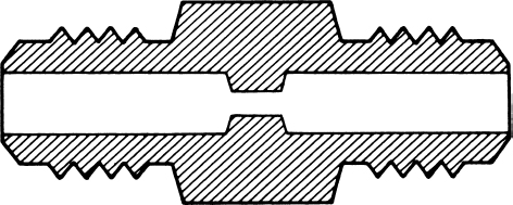
FIGURE 13-51 Drawing of an orifice.
Figure 13-52 is a drawing of a variable restrictor. In this drawing, there are two horizontal ports and a vertical, adjustable needle valve. The size of the passage through which the hydraulic fluid must flow may be adjusted by screwing the needle valve in or out. The fact that the passage can be varied in size is the feature that distinguishes the variable restrictor from the simple fixed orifice.

FIGURE 13-52 A variable restrictor.
Check Valves
It is often necessary to prevent hydraulic fluid flow in one direction while permitting free flow in the opposite direction. The check valve is designed to accomplish this purpose. The construction of a simple ball check valve is shown in Fig. 13-53. Fluid pressure at port A will tend to push the ball off its seat and allow the fluid to flow through the valve. When the pressure is applied at port B, the ball will hold firmly on its seat and prevent the flow of fluid. Check valves are used as individual units in hydraulic systems, and they are also used as components of more complex valves and devices to control the flow of fluid in a given direction.

FIGURE 13-53 A ball check valve.
During the installation of a check valve, the technician must observe the direction of flow indicated on the body of the valve. Usually there is an arrow on the body or case of the valve to show the direction of the free fluid flow.
Orifice Check Valve
An orifice check valve is designed to provide free flow of hydraulic fluid in one direction and restricted flow in the opposite direction. One of the most common applications of this device is in the UP line of a landing-gear system. Since landing gear is usually quite heavy, it tends to fall too rapidly upon lowering, unless some means of restricting its movement is utilized. Since the UP line of a landing-gear actuating cylinder is the return line for hydraulic fluid from the actuating cylinder to the reservoir, any restriction in this line will limit the movement of the gear. That is, the gear movement must await the flow of the return fluid as it moves toward the down position.
An orifice check valve is also used for certain flap-control systems. Because of the air pressure on the flaps during flight, there is a continuous force tending to raise the flaps to a streamlined position. It is therefore advisable in some systems to restrict the UP movement by placing an orifice check valve in the DOWN line of the flap system.
The construction of an orifice check valve is illustrated in Fig. 13-54. When the valve is on its seat, fluid flow can occur only through the center orifice, but when the fluid flow is in the opposite direction, the valve moves off its seat and there is free flow of the hydraulic fluid through multiple openings.

FIGURE 13-54 Construction of an orifice check valve.
The improper installation of an orifice check valve in a landing-gear system can cause serious problems. If the valve is installed in the reverse position, the movement of the landing gear is restricted as the gear is raised, but there is free flow as it is lowered. The hydraulic pressure in the system plus the force of gravity causes the gear to lower with excessive speed; when it reaches the end of its travel, the inertial forces are likely to damage the aircraft structure because of the sudden stop.
Metering Check Valve
A metering check valve, sometimes called a one-way restrictor, serves the same purpose as an orifice check valve. However, the metering check valve is adjustable, whereas an orifice check valve is not.
A drawing of a metering check valve is shown in Fig. 13-55. This unit has a housing, a metering pin, and a check-valve assembly. The pin is adjusted to hold the ball slightly off its seat. When fluid enters port B, it forces the ball away from its seat and then flows out through port A to the actuating cylinder. When the flow of fluid is reversed, the fluid entering from the actuating cylinder flows through the tiny opening between the ball and its seat, thus restricting the flow. By adjusting the metering pin in or out with a screwdriver, the rate at which the fluid can return from the actuating cylinder is controlled, because the position of the metering pin changes the width of the opening between the ball and its seat.
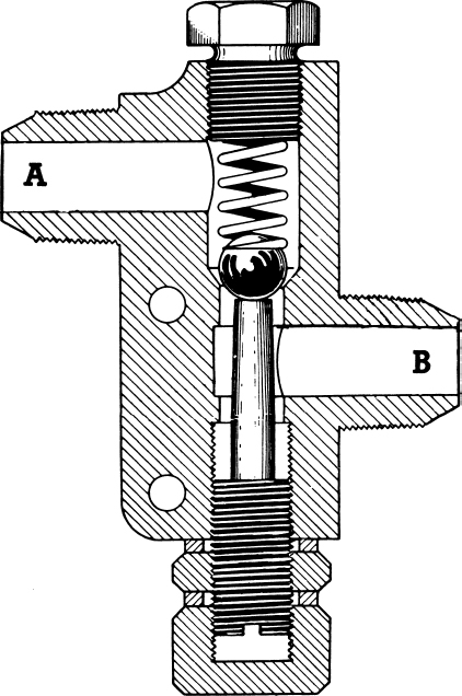
FIGURE 13-55 A metering check valve.
Hydraulic Fuse
The hydraulic fuse shown in Fig. 13-56 is a device designed to seal off a broken hydraulic line and prevent excessive loss of fluid. It permits normal flow in a line; but if the flow increases above an established level, the valve in the fuse closes the line and prevents further flow.
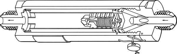
FIGURE 13-56 A hydraulic fuse.
In reference to the figure, fluid enters the fuse through the passage at the right and flows between the outer case and the inner cylinder. It then passes through cutouts in the left end of the inner cylinder and out though the center opening. At the right end of the inner cylinder is a metering orifice, which permits a small amount of fluid to enter the cylinder behind the poppet valve.
During normal operation the pressure of this fluid is approximately the same as the pressure on the opposite side of this poppet; therefore, there is no movement of the poppet. As fluid flow increases, the pressure differential across the poppet also increases. If this differential becomes excessive, the poppet moves to the left and closes the exit port of the fuse, thus stopping the fluid flow. The fuse remains closed only as long as a substantial pressure differential exists. If the pressure differential decreases to a certain predetermined level, the spring unseats the poppet and permits normal flow to resume.
Sequence Valve
A sequence valve is sometimes called a timing valve because it times certain hydraulic operations in proper sequence. A common example of the use of this valve is in a landing-gear system, where the landing-gear doors must be opened before the gear is extended and the gear must be retracted before the doors are closed.
Figure 13-57 is a drawing of a sequence valve. It is essentially a bypass check valve that is automatically operated. There is a free flow of hydraulic fluid from port A to port B, but the flow from B to A is prevented unless the ball is unseated by depressing the plunger.

FIGURE 13-57 A sequence valve.
Figure 13-58 is a schematic diagram of a landing-gear system with sequence valves. During the retraction of the landing gear, the fluid flows under pump pressure from the selector valve to the landing-gear cylinder and to sequence valve A. In this position, sequence valve A is closed, thus preventing the fluid from entering the door cylinder. As the landing-gear actuating-cylinder piston approaches the end of its travel, either the piston rod or some other part of the landing-gear mechanism depresses the plunger of the sequence valve, thereby permitting the fluid to flow to the door-actuating cylinder and to close the doors. The fluid displaced at the other end of the landing-gear actuating cylinder by the motion of the piston passes to the DOWN line through sequence valve B. The flow is not restricted, because it is flowing directly from port A to port B in the sequence valve illustrated in Fig. 13-57.
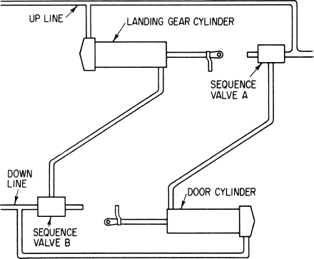
FIGURE 13-58 Landing-gear system with sequence valves.
During the extension of the landing gear, the fluid under system pressure flows through the DOWN line and enters the door-actuating cylinder, but it is prevented from moving the landing-gear actuating-cylinder piston because sequence valve B is closed. However, when the door actuating-cylinder piston reaches the limit of its travel, the plunger on sequence valve B is depressed, and a passage is opened for the fluid to enter the landing-gear actuating cylinder and extend the gear. The fluid displaced by the motion of the door’s actuating-cylinder piston flows to the UP line through sequence valve A without restriction.
Sequence valves are sometimes used in conjunction with hydraulically operated landing-gear UP locks and DOWN locks. In such instances, the sequence valve either blocks the fluid from the landing-gear actuating cylinder until the unlocking cylinder has released the lock or prevents the fluid from entering the locking cylinder until the landing gear has reached its fully retracted or extended position. Sometimes the sequence valve and the unlocking cylinder are manufactured as one unit.
To illustrate the operation of a sequence valve in a landing-gear system, the drawing of Fig. 13-59 is provided. This drawing shows a view of the sequence valve in the open position. If the valve is installed with port B connected to the landing gear UP line and port A connected to the gear door-actuating cylinder, fluid entering at port B cannot pass through to the actuating cylinder until the landing gear has been retracted and the valve plunger pressed in, as shown in the drawing. Therefore, the gear doors cannot be closed until the gear is retracted.

FIGURE 13-59 Sequence valve in open position.
For the part of the system extending the landing gear, the sequence valve is installed with port B connected to the DOWN line of the landing-gear actuating cylinder. The plunger of the valve is not depressed until the gear doors are open; therefore, the gear cannot be extended until the door operation is nearly complete.
If, in the installation and adjustment of the landing gear system, the sequence valves are not set correctly, it is possible for the landing gear to strike the gear doors.
Shuttle Valve
Quite frequently in hydraulic systems it is necessary to provide alternative or emergency sources of power with which to operate critical parts of the system. This is particularly true of landing-gear systems in the case of hydraulic-pump failure. Sometimes the landing gear is operated by an emergency hand pump and sometimes by a volume of compressed air or gas stored in a high-pressure air bottle. In either case it is necessary to have a means of disconnecting the normal source of hydraulic power and connecting the emergency source of power. This is the function of the shuttle valve.
The operation of a shuttle valve is shown in the drawings of Fig. 13-60. Port 1 of the valve is the normal entrance for hydraulic fluid from the pressure system. Port 2 is the outlet leading to the DOWN line of the landing-gear actuating cylinder. In view A the valve is in the normal position with free passage of fluid from port 1 to port 2. If main system pressure fails and it is desired to lower the landing gear, the landing-gear selector valve is placed in the DOWN position and emergency pressure is applied to port 3. As explained previously, this pressure can come from an emergency pump or from a high-pressure air bottle. The emergency pressure forces the shuttle valve to the left, as in view B, and opens port 2 to port 3; thus fluid or air is permitted to flow through the valve to the DOWN line of the actuating cylinder. Return fluid from the cylinder will flow through the normal UP line, back through the main selector valve, and to the reservoir.

FIGURE 13-60 Operation of a shuttle valve.
The installation of a shuttle valve in a landing-gear system is shown in the schematic drawing of Fig. 13-61. The DOWN line is blocked when emergency pressure is applied, and emergency fluid or air enters the cylinder, flowing from port 3 to port 2 and into the actuating cylinder.

FIGURE 13-61 Location of a shuttle valve in a landing-gear system.
Priority Valve
A priority valve is a sequence valve that is operated by hydraulic pressure rather than by a mechanical means. This valve is used to allow one actuator to operate and complete its operation before allowing a second component to operate. This gives the first component a priority over the second, resulting in the name “priority valve.” A priority valve is represented in Fig. 13-62, and a simplified system using a priority valve is shown in Fig. 13-63. When actuators A and B are both selected at the same time, pressure is available at the intersection of the lines. The priority valve in the line for actuator B requires that full-system pressure be applied to it to overcome the spring that is holding the spool closed. Since fluid is flowing to actuator A, the pressure is below the operating value of the valve. Once actuator A has stopped moving and the hydraulic pressure is up to near full value, the poppet has enough pressure applied to it to off-seat the spool valve and allow fluid to flow to actuator B. When fluid flows in the opposite direction, the seat shifts to the left and a free flow of fluid occurs.
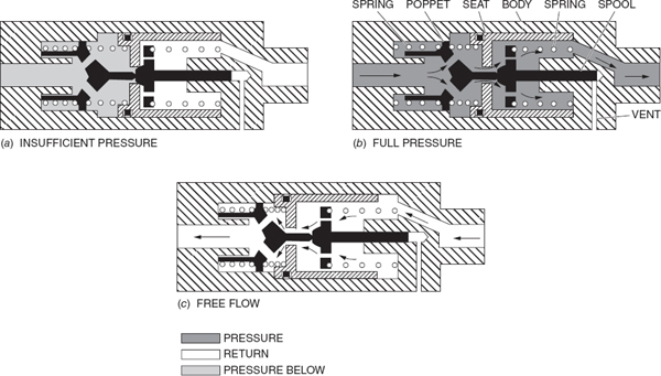
FIGURE 13-62 A priority valve.

FIGURE 13-63 Location of priority valve in a system.
The valve shown is a priority valve used for sequencing, but these valves are also used to give one component priority over another component in unrelated operations. For example, in some aircraft, a priority valve is used to give the flight-control actuators priority to system pressure over the landing gear and flap systems.
Flow Equalizers
The hydraulic flow equalizer is a unit that hydraulically synchronizes the movement of two actuating cylinders. To do this, it divides a single stream of fluid from the selector valve into two equal streams, causing each cylinder to receive the same rate of flow and both to move in unison. The flow equalizer also combines two streams of fluid at an equal rate; therefore, it synchronizes the actuating cylinders in both directions. Since this unit equally divides the combined flow, it is said to be dual acting. This unit is actually two constant-flow valves joined together with check-valve features to provide for reverse flow.
Figure 13-64 illustrates how the flow equalizer synchronizes the movement of the actuating cylinders in both directions. In the left-hand illustration, the equalizer is splitting the flow to extend to the pistons. The right-hand illustration shows the valve combining the two streams coming from the cylinders as the pistons retract. The two cylinders will move at the same rate and will always be synchronized even though unequal loads and pressure exist.

FIGURE 13-64 Flow equalizer installation.
The type of flow equalizer shown in Fig. 13-65 is used to divide the pump’s fluid output in the two different systems. Fluid enters the inlet port (C), where it pushes down the plug (D) and uncovers the two fixed orifices in the sleeve (B). The fluid then splits and tends to flow equally down the two side passages (A and E). It then flows through the two splitting check valves (G and P) and metering grooves (K and O) in the valve body. It then flows out the exit ports (J and N) to the actuating cylinders. Any difference in the rate of flow between the two passages results in a pressure differential between these passages. Then the free-floating metering piston (L) shifts to equalize the internal pressures, and the flow equalizes. If the pressures are different in the exit ports (J and N), there will also be a difference in the pressure drops across the metering orifices (K and O), with the greatest drop in the orifice leading to the line with least pressure in it.
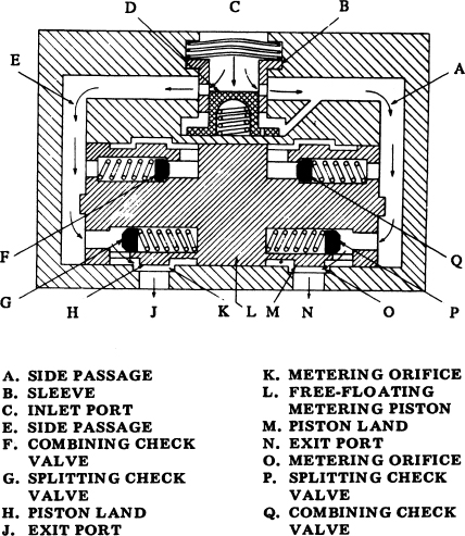
FIGURE 13-65 Flow equalizer—splitting position.
To illustrate this equalizing action, assume that the actuating cylinder attached to the left-hand exit port (J) moves easier than the one attached to the right-hand exit port (N), The fluid would then try to flow faster out the left-hand exit port, but in doing so it must also flow faster through the left-hand fixed orifice, creating a greater pressure drop.
Fluid leaving the exit port (N) meets with more resistance, so the flow down the right-hand passageway would tend to be slower, causing a reduced pressure drop across the right fixed orifice and creating a greater pressure in passage A. This momentary pressure differential forces the free-floating metering piston (L) to the left, causing the space between the piston land (H) and the metering groove (K) to become smaller, which restricts the flow of fluid out the left-hand exit port (J). The flow equalizer imposes a restriction of the fluid that has a tendency toward faster flow, and the two streams are equalized.
HYDRAULIC ACTUATORS
Hydraulic actuators are devices for converting hydraulic pressure to mechanical motion (work). The most commonly utilized actuator is the actuating cylinder; however, servo actuators and hydraulic motors are also employed for special applications where modified motion is required. Actuating cylinders are used for direct and positive movement such as retracting and extending landing gear and the extension and retraction of wing flaps, spoilers, and slats. Servo actuators are employed in situations where accurately controlled intermediate positions of units are required. The servo unit feeds back position information to the pilot’s control, thus making it possible for the pilot to select any control position required. The servo actuator is used to move large control surfaces such as the rudder, elevator, and ailerons. Servo units are also used to aid the pilot in the operation of cyclic and collective pitch controls in a helicopter.
Actuating Cylinders
The design of actuating cylinders is determined by the functions that they are to perform. Different types of actuating cylinders are shown in Fig. 13-66. The cylinder shown in Fig. 13-66(a) is a single-acting cylinder. Hydraulic pressure is applied to one side of the piston to provide force in one direction only. When hydraulic pressure is removed from the piston, a return spring moves the piston to its start position.

FIGURE 13-66 Actuating cylinders.
A double-acting actuating cylinder is designed so hydraulic pressure can be applied to both sides of the piston. Thus, the cylinder can provide force in either direction. A double-acting cylinder is shown in Fig. 13-66(b). This type of cylinder is used for the operation of retractable landing gear, wing flaps, spoilers, etc.
Many variations of the basic actuator cylinder have been designed, usually for special applications. The technician will find information on these in the applicable manufacturer’s maintenance manuals.
Internal-Lock-Type Actuator
The internal-lock actuator allows the hydraulically operated mechanism to be locked in one of the extreme positions without the use of an external locking device. Figure 13-67 illustrates a typical actuating cylinder (B) incorporating internal locks and shows the actuator in both the locked (upper drawing) and unlocked (lower drawing) positions. In the locked position (upper), the locking segment (M) is positioned behind the lip of the concave head of the piston (C) when fully retracted. The lock spring (G) positions the lock rod piston (J) to the right; the lock rod piston, in turn, extends the toggle (L) and positions the locking segment (M).
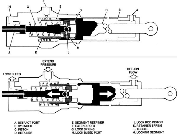
FIGURE 13-67 Internal-lock-type actuating cylinder.
To unlock and extend the piston (C), fluid under pressure enters the extend port (F) and is directed through passageways to the head of both the piston (C) and the lock rod piston (J). Sine the piston (C) cannot move until the actuator is unlocked, the lock-rod piston (J) must first be moved to the left. Although the pressure is equal on both sides of the head of the lock-rod piston (J), the difference in working areas allows it to be moved to the left. This action compresses the lock spring (G) and allows the toggle (L) to collapse, so that the main actuating piston (C) can force the locking segment (M) inward as the piston begins to extend to the right. The piston (C) movement then allows the retainer spring (K) (which was compressed by the piston on the retract cycle) to move the segment retainer (E) to the right, as shown in the bottom portion of Fig. 13-67. This position holds the locking segment (M) in the retainer (D) while the piston (C) is in the extended position. This prevents the locking segment (M) from interfering with the piston (C) on the retract cycle.
To retract and lock the piston, fluid under pressure enters the retract port (A) and is directed to the piston head. When the piston (C) has retracted a specified distance, the piston head contacts the segment retainer (E) to move it to the left. As the segment retainer moves to the left, it compresses the retainer spring (K). After the piston (C) moves sufficiently to the left (fully retracted position), the lock spring (G) positions the lock rod piston (J) to the right, thus extending the toggle (L). This, in turn, positions the locking segment (M) behind the lip of the concave piston head to lock the actuator in the locked position.
The lock bleed port (H), which is connected to the return line, ensures the positive movement of the lock rod piston (J) by preventing the small amount of operational leakage around the shaft from building up pressure and creating a fluid lock. The hollow portion of the lock and piston shaft can be used for the attachment of a cable operated control so that the actuator can be unlocked manually during an emergency or ground operation.
This type of actuator can be used in many hydraulically operated subsystems and is ideal for hydraulically operated doors.
Servo Actuators
Aircraft equipped with fly-by-wire systems often use servo actuators to position the flight control surfaces. These are called power control units (PMUs) on Boeing aircraft or hydraulic jacks on Airbus aircraft. The PMU consists of an electrohydraulic control valve (EHCV) and an integrated hydraulic actuator. Motion transducers on the control column send a signal through the flight computer to the PMU which in turn moves the flight control. An actuator position feedback signal will be sent back to the flight computer.
A servo actuator is designed to provide hydraulic power to aid the pilot in the movement of various aircraft controls. Such actuators usually include an actuating cylinder, a multiport flow-control valve, check valves, and relief valves together with connecting linkages. Figures 13-68 and 13-69 show the components of a servo actuator. When the pilot moves a cockpit control in a particular direction, force is applied to the flow control valve in the actuator, causing it to direct fluid pressure to the actuating cylinder. The piston in the actuating cylinder moves in a direction to assist the pilot in moving the flight control. As the piston moves to the position called for by the pilot’s control, the linkage between the piston and the flow-control valve moves the flow-control valve back to a neutral position and stops the flow of hydraulic fluid and, therefore, the movement of the piston. The reverse action takes place when the pilot moves the cockpit control in the opposite direction.
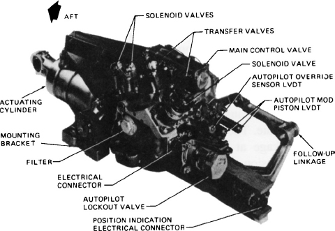
FIGURE 13-68 A servo actuator.
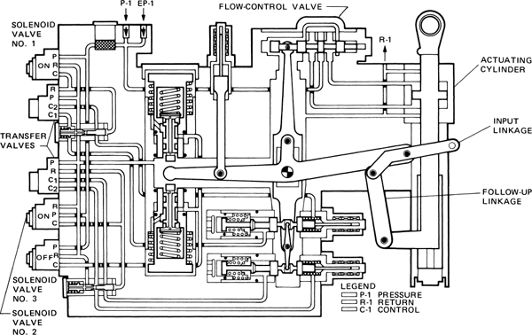
FIGURE 13-69 A servo actuator.
Hydraulic Motors
A hydraulic motor is illustrated in Fig. 13-70. Note that the motor is almost identical to the multiple-piston hydraulic pump described previously. When hydraulic fluid pressure is applied to the input port, it forces the pistons downward in the cylinders. Since the cylinder block axis is at an angle to the axis of the output shaft, the extension of the piston rods causes both the cylinder block and the output shaft to rotate. The two assemblies are connected by a universal linkage at the center. As each piston reaches its fullest extension, the cylinder is rotated past the input slot in the valve plate and on to the return slot. The piston is then moved inward in the cylinder, and the hydraulic fluid is discharged to the return line. The rpm of the hydraulic motor depends upon hydraulic fluid pressure and the load on the motor.

FIGURE 13-70 A hydraulic motor.
A hydraulic motor has the advantage over an electric motor of being able to operate through a wide range of speeds from 0 rpm to the maximum for the particular motor. Variable-speed electric motors can provide some flexibility in the rate of actuation; however, they lose efficiency as speed decreases.
HYDRAULIC PLUMBING COMPONENTS
As indicated previously, the various operating devices of a hydraulic system require tubing, fittings, seals, couplings, and hoses to transmit fluid pressure from unit to unit. To prevent leakage and ensure effective operation, various types of seals are employed. These are described in this section; however, there are so many different types that this section is limited to those that are likely to be encountered by the aircraft technician. Information regarding hydraulic lines and fittings can be found in the text, Aircraft Basic Science.
Seals and Packings
The purpose of hydraulic packing rings and seals is to prevent leakage of the hydraulic fluid and thereby preserve the pressure in the aircraft hydraulic system. Seals are installed in most of the units that contain moving parts, such as actuating cylinders, valves, and pumps. Packing rings, seals, and gaskets are made in a variety of shapes and sizes.
Seals used in hydraulic and pneumatic systems and components are of two general classes, packings and gaskets. Packing rings are used to provide a seal between two parts of a unit that move in relation to each other. The gasket is used as a seal between two stationary parts. This classification will apply in most cases; however, deviations will be found in some instances.
The handling, installation, and inspection of rings, seals, and gaskets in an aircraft hydraulic system are extremely important because a scratched or nicked packing ring can cause the failure of a unit in the system at a critical time.
Typical shapes for hydraulic packing rings, seals, and gaskets are shown in Fig. 13-71. These drawings show the standard O-ring seal, chevron seal, universal gasket, and crush washer.

FIGURE 13-71 Shapes for packing rings, seals, and gaskets.
The O-ring seal is probably the most common type used for sealing pistons and rods because it is effective in both directions. A color code on the O-ring seal identifies the type of system in which it is used and, generally, the manufacturer. O-rings have either a series of colored dots arranged clockwise or a colored stripe around the outer circumference. The first dot, reading in a clockwise direction or the stripe indicates the system in which the O-ring is used. The following color codes are used: Red indicates use in the fuel systems only; blue indicates use in hydraulic and pneumatic systems; and yellow indicates use in oil systems only. Note: A white dot appearing first indicates a nonstandard seal. The second dot indicates the system. A white dash with a yellow dot 90° from the dash indicates a system using Skydrol.
Generally, the O-ring seal requires no adjustment when it is installed. Figure 13-72 shows a typical O-ring installation. However, a few precautions must be observed at installation, or early failure will result. Always install new O-rings with each disassembly. Do not use old rings that have been in service. The seal must be the correct size and installed without defects such as cuts, nicks, or other flaws. The seal and O-ring groove must be lubricated freely with the same type of hydraulic fluid that is used in the system unless otherwise specified in the repair manual. Care must be exercised when installing O-rings to prevent scratching or cutting the seal on threads or sharp comers. Also, make certain that the O-ring is not installed in a twisted condition; otherwise it will not function correctly.

FIGURE 13-72 Typical O-ring installation.
The O-ring seal should not be used alone in a system where the pressure is greater than 1500 psi [10 342.5 kPa]. If the hydraulic pressure is too great, the ring can become pinched between the moving part and stationary part of the unit, as is shown in Fig. 13-73, thus damaging the ring and destroying the seal. When the O-ring is used in higher-pressure systems, backup rings are installed. Backup rings are used in conjunction with seals subjected to high pressure. Their purpose is to prevent the high pressures from pinching the seal between the moving and stationary parts, such as between a piston and cylinder wall. They give additional strength to the seal. Backup rings are usually made of Teflon.

FIGURE 13-73 O-ring seal, pinched condition.
If pressure is exerted on the seal in one direction only, the backup ring should be placed on the side away from the pressure. Where the pressure is exerted alternately in each direction, these backup rings are installed on both sides of the O-ring. Proper installation of backup rings is shown in Fig. 13-74.
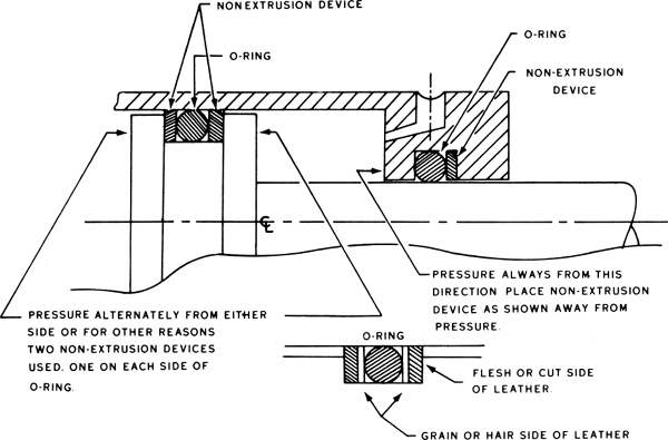
FIGURE 13-74 O-ring seal with backup ring.
The V-shaped (chevron) seal and the U-shaped seal must be installed with the same care as that used for other types of seals. The size of the seal must be correct and there must be no nicks, scratches, or other damage on the seals. When high pressure is exerted in only one direction, one set of seals is sufficient, but when the pressure is alternately applied, first in one direction and then in the other, two sets of seals are required because this type of seal works effectively in only one direction. The installation of a dual set of chevron seals is shown in Fig. 13-75.
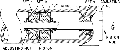
FIGURE 13-75 Installation of a dual set of chevron seals.
The general procedure to follow in installing V-shaped or U-shaped seals is as follows:
1. Install one ring at a time, being sure that it is seated properly. Never install such rings in sets.
2. Use shim stock (very thin metal sheet) to protect the packing rings if the packing crosses sharp edges or threads. The shim stock should be from 0.003 to 0.010 in [0.076 to 0.254 mm] thick. It is rolled and then placed over the threads or sharp edges. After the packing is installed, the shim stock is removed.
3. If the unit in which the packing is being installed does not have an adjustable packing gland nut, insert metal shims of graduated thickness behind the adapters to hold the packing securely in place.
4. If the unit in which the packing is being installed has an adjustable packing gland, adjust the gland nut until the V-ring stack is held together firmly but not squeezed. The gland nut is then loosened to the first lock point.
5. Whenever possible, the technician should check the unit by hand for free operation after installation before the hydraulic pressure is applied.
6. In all cases, the technician should consult the manufacturer’s instructions regarding the installation of seals.
HYDRAULIC SYSTEMS FOR AIRCRAFT
Every aircraft hydraulic system has two major parts or sections, the power section and the actuating section (or sections). The power section provides for fluid flow, regulates and limits pressure, and carries fluid to the various selector valves in the system. The actuating section or subsystems are the sections containing the various operating units, such as the wing flaps, landing gear, brakes, boost systems, and steering mechanisms.
The power section may either be an open or a closed system using an engine-driven pump or a pump driven by an electric motor. Pressure developed by the pump in an open system is controlled by one of the following three valves: an open-center valve, a power-control valve, or a pump-control valve. An open system means there is a free path for fluid flow back to the reservoir until one of these units is actuated and directs fluid flow from the selector valve. Fluid flow is then directed to the actuators (cylinders, motors, etc.), and pressures will build sufficiently to move the actuating units.
All three types of open system valves are automatically shifted by hydraulic pressure to the open position after the units have been actuated. All three type valves employ time-lag or resistance features to prevent them from shifting to “bypass” too soon, which would result in a loss of fluid flow and pressure to the units before the hydraulic cycle has been completed. When the power valve, pump-control valve, or the open-center valve is in the bypass position, the pump is said to be idling under no load and with little power-input requirement.
In a closed system the pressure developed by the engine-driven or electric motor-driven power pump may be regulated by a pressure regulator (unloading valve), by the power pump (which would then have an integral control valve), or by a pressure switch (which would shut off the pump driven by an electric motor when the desired system pressure is reached). The closed system will always have fluid stored under pressure whenever the power pump is operating. However, after system pressure is built up to a predetermined value, the load is automatically removed from the pump by an unloading valve called the pressure regulator or the integral control valve of the pump (called the compensator valve, which controls the pump output). In this way the pump is allowed to idle when no units are in operation and until there is further demand upon the system.
Open Systems
An open system is one having fluid flow but no appreciable pressure in the system whenever the actuating mechanisms are idle. Fluid circulates from the reservoir, through the pump, through the open valves, and back to the reservoir, as illustrated in the upper drawing of Fig. 13-76. This system is also called an open-center system. Selector valves in an open system (using an open-center valve) are always connected in series with each other, an arrangement whereby the pressure line goes through each selector valve. Fluid is allowed free passage through each selector valve and back to the reservoir until one of the selector valves is positioned to operate a mechanism, as illustrated in the lower drawing of Fig. 13-76. Fluid is then directed to the actuator, and pressure is allowed to build up in the systems. A pump-control valve or a power-control valve is placed in a line that goes directly from the pump to the reservoir. When closed, these valves block the flow to the reservoir and force the flow to a two-position valve and then to one of the actuating units.
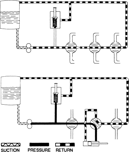
FIGURE 13-76 Basic open-center system.
A typical open system is shown in Fig. 13-77. This system is a combination closed and open system, with both parts of the system receiving their fluid supply from the same engine-driven constant-volume power pump. The pump supply is divided equally to the two systems by a flow equalizer. Other units included in the closed section of the system are discussed at a later time.

FIGURE 13-77 Power section with open-center flow.
Open systems develop no pressure except when a mechanism is being operated; the pressure is then metered by the selector valve and limited by a relief valve. Each subsystem has an individual relief valve that limits the maximum pressure of the system.
One of the advantages of the open-center system is that it does not require expensive and complicated pressure regulators; the power pump can be a simple gear pump, although a fixed-displacement piston pump may be used.
A disadvantage of the open-center system is that the operation of only one subsystem at a time is possible without interference from other systems. For example, if the flap subsystem precedes the landing-gear subsystem and the two systems are operated at the same time, the speed of gear operation will be limited by the amount of fluid returning from the flap-actuating cylinder. As soon as the flap operation is complete and the flap-selector valve kicks out, the landing-gear operation proceeds at its normal rate.
Open systems are generally found only on light, general aviation aircraft. Transport-category aircraft require more complex systems, which may have several units operating at the same time.
Closed Systems
A closed system is one that directs fluid flow to the main system manifold and builds up pressure (stores fluid under pressure) in that portion of the system that leads to all the selector valves. There are two basic types of closed systems. One has a constant-volume pump and a pressure regulator to control the pressure at a working range and to “unload” the pump when there is no flow requirement and pressure builds up in the system manifold; the second closed system utilizes a variable-volume pump and directs the flow to the system manifold, similar to the constant-volume system. The output of the variable-volume pump is controlled by an integral control valve. This valve reduces the pump flow to zero when no units are operating in the system and pressure is built up in the storage chambers, called accumulators. The pump may be driven by either an engine or by an electric motor. The means of pressure control and the means of driving the pump may vary, but all closed systems are basically the same. Any number of subsystems may be incorporated in a closed system, but subsystems differ from the open system in that the selector valves are arranged in parallel rather than in series. The pressure regulator (as used in constant-volume systems) directs the flow of the pump (or pumps) either to the system or to the reservoir, depending upon the existing system pressure. System pressure is always maintained between the kick-out and kick-in settings of the regulator when the actuating mechanisms are not in operation.
When a selector valve is positioned to operate a mechanism, the system pressure drops until it reaches the kick-in settings of the regulator, at which time the pump again directs the flow into the system to increase the system pressure until the maximum setting of the regulator is reached again. The accumulator used in the system stores fluid under pressure, stabilizes system pressure, and ensures smooth operation of the regulator. A system relief valve safeguards the system if the regulator fails.
Multiple power pumps are used in many hydraulic closed systems. Normally they are used in multiengine aircraft, where they can be driven by separate engines. This ensures hydraulic system operation in the event of an engine failure or the failure of one of the pumps. Figure 13-78 shows how dual power pumps are connected into the system. Notice that both pumps supply the same system by combining their volume output into a common pressure manifold. The pumps may be either the constant-volume type or the variable-volume type.

FIGURE 13-78 Closed system using dual pumps.
Figure 13-79 is a schematic drawing of a direct pressure system that has its pressure regulated by an unloading valve (pressure regulator) operating in conjunction with an accumulator. This system is also termed a closed-center system.

FIGURE 13-79 Hydraulic system with a pressure regulator.
When the actuating equipment is not in use, pressure is relieved from the continuously operating engine-driven pump by means of the unloading valve after the accumulator is charged to the correct level. As soon as a subsystem is operated, pressure first comes from the accumulator for operation; when accumulator pressure has dropped to a predetermined level, the unloading valve kicks in and directs pump flow to the operating system. A study of the diagram shows that the pump output flows directly through the unloading valve and back to the reservoir when no pressure is required. When a subsystem (brakes, landing gear, or flaps) is operated, pump pressure flows through the subsystem and back to the reservoir through the subsystem return line.
The main relief valve in the system is located between the unloading valve and the return line. If the unloading valve should become stuck in the kicked-in position, the excess pressure would be bypassed through the relief valve to the reservoir. The pressure gauge would show higher than normal pressure, and the system would probably be making noise because of the operation of the relief valve. The relief valve is usually set at least 100 psi [689.5 kPa] above the normal operating pressure.
Light-Aircraft Hydraulic Systems
A schematic diagram of a hydraulic system for a light, multiengine airplane is shown in Fig. 13-80. The diagram shows that the engine-driven hydraulic pump (10) draws hydraulic fluid from the reservoir (15) and pumps it through the pressure port of the “Powerpak” assembly into the landing-gear-selector pressure chamber. When the two selector valves are in the neutral position, the fluid travels from the landing-gear selector valve (1) through the flap selector valve (2) and back to the reservoir.
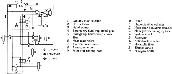
FIGURE 13-80 Schematic diagram of the hydraulic system for a light twin-engined airplane. (Piper Aircraft Co.)
The Powerpak assembly is a modular unit that includes the reservoir, relief valve, hand pump, landing-gear selector valve, wing-flap selector valve, filters, and numerous other small parts essential to the operation. When both selector valves are in the neutral position, the system acts as an open-center system, in that the fluid flows first through one selector valve and then through the other before returning to the reservoir. During this time the fluid flows freely at a reduced pressure. Since the fluid supply line runs first through the landing-gear selector valve, the flaps cannot be operated while the landing-gear subsystem is in operation. Each selector valve has a separate return line to allow fluid from the actuating cylinder or cylinders to flow back to the reservoir.
The diagram of Fig. 13-81 shows the fluid flow when the landing-gear selector is placed in the UP position. When the selector valve is placed in either operating position, it is held in the position by a detent consisting of a ball, O-ring, plunger, and spring. The ball snaps into a groove in the spool, which operates the poppet valves and prevents the spool from moving linearly until the operation is complete. When the actuating cylinder reaches the end of its movement, pressure builds up to approximately 1150 psi [7829 kPa]. This pressure acts against the plunger of the detent mechanism and relieves the pressure of the spring, thus allowing the ball to pop out of the groove. A spring then causes the spool and selector lever to return to the neutral position.

FIGURE 13-81 Diagram to show fluid flow when the landing-gear selector valve is in the UP position. (Piper Aircraft Co.)
Figure 13-82 shows the fluid flow in the system when the wing-flap selector valve is placed in the DOWN position. The action is generally the same as that described in the foregoing paragraph. Note that the fluid to the flap-selector valve has passed through the landing-gear selector valve first and that the landing-gear valve is in the neutral position.

FIGURE 13-82 Fluid flow when the wing-flap selector valve is in the DOWN position. (Piper Aircraft Co.)
The fluid used in the just-described system is petroleum type, MIL-0-5606. The operating pressure is 1150 psi [7829 kPa], and the main relief valve “cracking” pressure is 1250 to 1300 psi [8618.8 to 8963.5 kPa]. Thermal relief valves are set to open at 2000 to 2050 psi [13 790 to 14 134.8 kPa] or 1850 to 1900 psi [12 755.8 to 13 100.5 kPa], depending upon the particular model of Powerpak. The main reservoir capacity is approximately 4.5 p [2.13 L], with an emergency supply of 0.95 p [0.45 L].
Another example of a comparatively simple hydraulic system is illustrated in Fig. 13-83. Since this system serves one function only, raising and lowering the landing gear, it requires no selector valves. Direction of fluid flow is controlled by the reversible, electrically driven pump.

FIGURE 13-83 Hydraulic system for landing-gear operation. (Piper Aircraft Co.)
The reservoir, gear pump, relief valves, reversible motor, filter, and shuttle valve are all integrated into one assembly. A pressure switch is installed on a cross fitting connected to the pump-mount assembly. This switch opens the electrical circuit to the pump solenoid when the gear fully retracts and the pressure in the system increases to approximately 1800 psi [12 400 kPa]. The switch continues to hold the circuit open until the system pressure drops to approximately 1500 psi [10 340 kPa], when it again operates to build up pressure as long as the gear-selector handle is in the UP position. The DOWN position of the selector does not affect the pressure switch.
The pump is a gear-type unit driven by a 14-V reversible motor designed to operate in a pressure range of 2000 to 2500 psi [13 790 to 17 237 kPa]. A thermal relief valve is connected to the gear-up pressure line to prevent excessive pressure due to thermal expansion of the fluid. This valve maintains pressure in the system up to 2350 + 50 psi [16 230 + 345 kPa]. An additional relief valve is incorporated in the system to return hydraulic fluid to the reservoir if pressure should exceed 4000 psi [27 436 kPa]. The shuttle valve, located in the base of the pump, allows fluid displaced by the actuating cylinder pistons to return to the reservoir without back pressure.
The system includes a free-fall valve that allows the landing gear to drop in the event of a system malfunction. The valve is controlled manually or by a gear backup extension device that is operated by a pressure-sensing chamber. This chamber moves the free-fall valve to lower the gear, regardless of gear-selector handle position, depending upon engine power (propeller slipstream) and airspeed. Landing-gear extension occurs even if the selector is in the UP position at airspeeds below approximately 118 mph [190 km/h] with engine power off. The device also prevents the gear from retracting at airspeeds below approximately 93 mph [150 km/h] at sea level with full power, even though the selector switch may be in the UP position. The sensing device operation is controlled by a differential air pressure across a flexible diaphragm, which is mechanically linked to the hydraulic free-fall valve and an electric switch that control the pump motor. A high-pressure and static air source for actuating the diaphragm is provided in a mast mounted on the left side of the fuselage above the wing. Manual override of the device is provided by an emergency gear lever. The emergency free-fall lever must be held in the UP position to retract the gear and in the DOWN position to extend the gear.
HYDRAULIC SYSTEM FOR THE BOEING 777 AIRLINER
The hydraulic system described here represents the installation of one particular model of the Boeing 777 airplane. The Boeing 777 incorporates three separate and independent hydraulic power systems. These are designated: left system, center system, and right system. Each hydraulic system has a pressurized reservoir. The left system receives fluid under pressure from the left engine–driven pump (EDP) and an AC-motor pump (ACMP). The center system receives fluid under pressure from two AC-driven pumps, two air-driven pumps (ADP), and the ram air turbine (RAT). The right system receives fluid under pressure from the right engine–driven pump and an AC motor pump. Figure 13-84 is a block diagram that shows the interconnections between units in each system and shows what aircraft subsystems are powered by what system. Note that there is no interconnection between the three systems. Two supply shutoff valves controlled by the engine fire switches are installed downstream of the reservoir to stop the flow of hydraulic fluid to the engine area in case of an engine failure or fire.
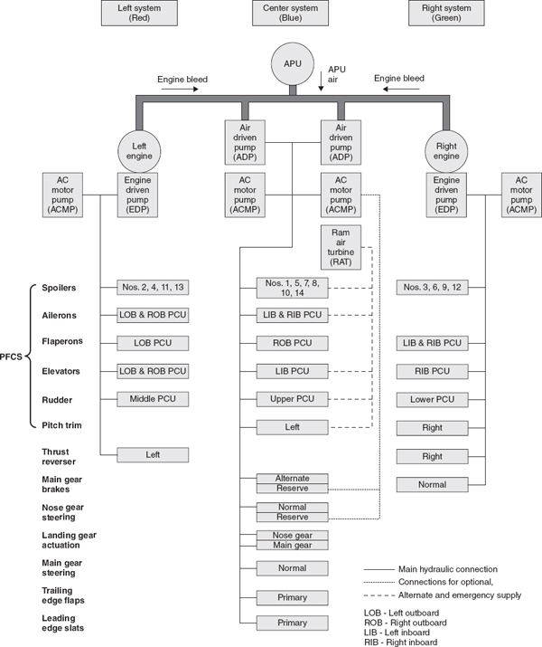
FIGURE 13-84 Schematic diagram of hydraulic power system for a Boeing 777 airplane. (Boeing Commercial Aircraft Co.)
Modular filter units are used in each system to combine a number of the smaller system components in one case to simplify maintenance. Each pump has its own filter module. For instance, the EDPs have a filter module that contains a temperature transducer, pressure transducer, ground servicing connection, filters, pressure relieve valve, and check valves for the direction of flow. Both the pump pressure output and the pump case drain line are routed through the filter module. The case drain line fluid is returned to the reservoir after being cooled in the heat exchanger. The ACMP has a filter module that contains filters, check valves, temperature transducer, and pressure transducer. The hydraulic fluid used for the Boeing 777 is Skydrol 5 (type V), a fire-resistant, phosphate ester-base, synthetic fluid. Servicing of any airplane’s hydraulic system must be accomplished according to the specific instructions issued by the manufacturer for the particular airplane. On the Boeing 777, the servicing station is located in the aft right-wing fairing area and is accessible through an access door. The filing equipment consists of a manually operated hand pump, hydraulic reservoir (system) selector valve, reservoir fill filter, and reservoir fill quantity gauge. The arrangement of the equipment in the filling area is shown in Fig. 13-85.
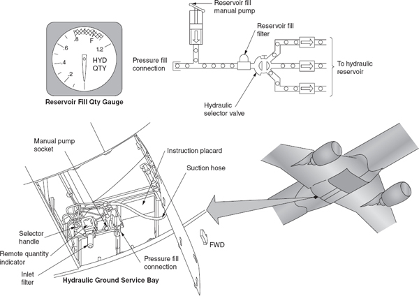
FIGURE 13-85 Hydraulic equipment in the filling area. (Boeing Commercial Aircraft Co.)
Left and Right Hydraulic Power System
The left and right hydraulic power supply systems are illustrated in the schematic drawing of Fig. 13-86. The left and right systems are very similar and therefore only the left system is discussed in this section. The left system is powered by an engine-driven pump mounted on engine 1 and an AC motor pump. The left system includes the equipment necessary to store, pressurize, deliver, control, monitor, and filter the hydraulic fluid to operate the systems previously noted. Hydraulic fluid for the system is stored in a reservoir that is pressurized by bleed air routed through a reservoir pressure module consisting of filters, check valves, restrictor valve, and pressure regulator to ensure a positive supply of hydraulic fluid to the pumps. The EDP and ACMP are variable delivery pumps that supply fluid to the various systems upon demand. The ACMP normally operates only when there is high hydraulic system demand. The EDP is equipped with an electrically controlled depressurizing valve to stop the flow of hydraulic fluid. Each pump has a filter module that contains various smaller power supply components such as filters, check valves, and temperature and pressure transducers. Hydraulic pump pressure and temperature information; reservoir pressure, temperature, and quantity information; and system pressure information is available on the airplane information management system (AIMS). Figure 13-87 shows the system information on AIMS. The EDP filter module also contains the system pressure relief valve. The pressure relief valve protects the system against damage in case a malfunction permits the pressure to rise to an abnormally high level. A hydraulic heat exchanger is installed in the pump case drain line to cool the hydraulic fluid that comes out of the pump case before it is returned to the reservoir.

FIGURE 13-86 Left/Right main hydraulic systems.
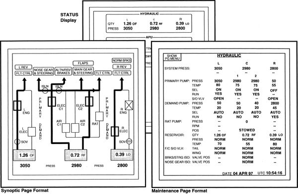
FIGURE 13-87 Hydraulic system indications shown on Aircraft Information Management System (AIMS).
Hydraulic Reservoir
The hydraulic system reservoirs (Fig. 13-88) of the left and right system contain the hydraulic fluid supply for the hydraulic pumps. The reservoir is pressurized by bleed air through a reservoir pressurization module; see Fig. 13-89.

FIGURE 13-88 Hydraulic reservoir of left and right system.
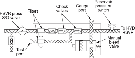
FIGURE 13-89 Reservoir pressurization module.
The engine-driven pump (EDP) draws fluid through a standpipe. The electrical pump (ACMP) draws fluid from the bottom of the reservoir. If the fluid level in the reservoir gets below the standpipe, the EDP cannot draw any fluid any longer and the ACMP is the only source of hydraulic power. The reservoir can be serviced through a center servicing point in the fuselage of the aircraft. The reservoir has a sample valve for contamination testing purposes, a temperature transmitter for temperature indication on the flight deck, a pressure transducer for reservoir pressure, and a drain valve for reservoir draining.
Modular Unit
There are two EDP modular filter units, four ACMP modular filter units, two ADP modular filter units, one RAT modular filter unit, and three return filter modular units. The EDP modular filter unit for the left system is shown in Fig. 13-90. As shown in this drawing this unit contains filters, check valves, a relief valve, ground service disconnect, pressure and temperature transducers, and differential pressure indicators. By bringing these units together in one unit, the maintenance of the system is simplified. A schematic flow diagram of the modular unit is shown in Fig. 13-91.
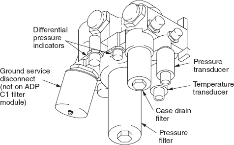
FIGURE 13-90 EDP modular filter module.

FIGURE 13-91 EDP modular filter module schematic.
The left system return filter module removes particles from the hydraulic fluid before the fluid returns to the reservoirs. Each module has these components: replaceable filter, automatic filter bowl removal shutoff valve, differential pressure indicator (red pop-up indicator), two check valves, bypass relief valve with indicator, and ground service disconnect. Return fluid from airplane hydraulic systems and the heat exchangers goes through the return filter modules before it goes into the hydraulic reservoirs again. The left and right return filter modules have a negative pressure loop. The negative pressure loop and the check valves permit backward flow of fluid from the reservoir to the system without back-flush of the filter. Bypass relief valves open to permit continued hydraulic flow if the filter clogs. The relief valve starts to open at approximately 165 psi.
Heat Exchanger
A heat exchanger in each hydraulic system cools the case drain hydraulic fluid from the EDPs and the ACMPs. This extends the service life of the fluid and the hydraulic pumps. The heat exchangers use aluminum-finned tubes to transfer heat from the fluid to the fuel. Fuel in the left and right main tanks cools the hydraulic fluid. The heat exchanger for the left hydraulic system is in the left main fuel tank between ribs 10 and 11. The heat exchanger for the right hydraulic system is in the right main fuel tank between ribs 10 and 11.
Accumulator
Four hydraulic accumulators absorb pressure changes caused by tail flight control power control unit (PCU) operation. This increases the life of the hydraulic system components. The right and center hydraulic systems each have a single hydraulic accumulator in the pressure lines to the tail flight controls. The left hydraulic system uses two accumulators that connect in the tail flight control pressure lines. All accumulators are the same and have a volume of 50 cubic inches. The accumulators have a hydraulic fluid side and a gas side. A fluid port connects the fluid side to the hydraulic line. Nitrogen is used to service the gas side of the accumulator. The hydraulic accumulators are on the forward side of the aft bulkhead of the stabilizer compartment. The hydraulic accumulator service panel is on the aft side of the stabilizer compartment aft bulkhead. Figure 13-92 shows the location of the accumulators in all three hydraulic systems.

FIGURE 13-92 Hydraulic system accumulators.
Valves
The valves incorporated in the left system are the relief valve, hydraulic supply shutoff valve, reservoir pressure shutoff valve, reservoir drain valve, and reservoir sample valve.
The purpose of the relief valve is to protect the system against excessive pressure.
The hydraulic supply shutoff valves are provided to stop the flow of hydraulic fluid to the engine area. These valves are electrically operated and are automatically shut off when the engine fire switch is operated.
The reservoir pressure shutoff valve is a manual shutoff valve placed in-line before the pressurization module.
The reservoir drain valve is a manual valve that is used to drain the fluid out of the reservoir.
The reservoir sample valve is a manual valve that is used to take a sample of hydraulic fluid for fluid analysis. Never use the drain valve for collecting a sample because the bottom of the reservoir could contain more contaminants.
Center Hydraulic System
Many of the components in the center system are identical to the components in the left and right system. Only the different system components are discussed. Figure 13-93 shows the center system schematic.

FIGURE 13-93 Center main hydraulic system.
Pumps
The center system has two AC motor pumps (ACMPs), two air-driven pumps (ADPs), and the ram air turbine (RAT) that can provide hydraulic power to the hydraulic subsystems. The AMPs only come on when there is a high demand such as landing gear retraction. The RAT can only supply power to the primary flight control surfaces (PFCS). Each pump has a filter module.
Center Hydraulic Isolation System
The center hydraulic isolation system (CHIS) supplies engine burst protection and a reserve brakes and steering function. CHIS operation is fully automatic and relays control the electric motors in the reserve and nose gear isolation valves. When the CHIS system is operational it prevents hydraulic operation of the leading edge slats.
The reserve and nose gear isolation valves are normally open. Both valves close if the quantity in the center system reservoir is low (less than 0.40) and the airspeed is more than 60 knots for more than 1 s. When CHIS is active, this divides the center hydraulic system into different parts. The NLG actuation and steering and the leading edge slat hydraulic lines are isolated from center system pressure. The output of ACMP C1 goes only to the alternate brake system.
The output of the other center hydraulic system pumps goes to the trailing edge flaps, the MLG actuation and steering, and the flight controls. If there is a leak in the NLG actuation and steering or LE slat lines, there is no further loss of hydraulic fluid. The alternate brakes, the trailing edge flaps, the MLG actuation and steering, and the PFCS continue to operate normally.
If there is a leak in the trailing edge flaps, the MLG actuation and steering, or the flight control lines, the reservoir loses fluid down to the standpipe level (0.00 indication). This causes a loss of these systems. But, the alternate brake system continues to get hydraulic power from ACMP C1. If there is a leak in the lines between ACMP C1 and the alternate brake system, all center hydraulic system fluid is lost.
Nose Gear Isolation Valve
The nose gear isolation valve will open for any of these conditions:
• Airspeed is less than 60 knots.
• Pump pressures for ACMP C2, ADP C1, ADP C2, and the RAT is less than 1200 psi for 30 s.
• Left and right engine rpm is above idle for 30 s.
• Left and right EDP pressure is more than 2400 psi for 30 s.
• The nose landing gear (NLG) is not up, the NLG doors are not closed, and the landing gear lever is not up for 30 s.
The first condition permits the flight crew to operate the NLG steering when airspeed is less than 60 knots (decreased rudder control authority during taxi). The second condition permits operation of the NLG actuation and steering if the hydraulic leak is in the part of the center hydraulic system isolated by the reserve isolation valve. The third condition permits operation of the NLG actuation and steering if there has not been an engine burst and the other hydraulic systems are pressurized. The nose gear isolation valve opens when pressure is necessary at the NLG. If the NLG is not fully retracted or the NLG doors are not closed, the nose gear isolation valve opens to let the NLG complete the retraction. When the landing gear lever is moved to the down position, the nose gear isolation valve opens to let the NLG extend with center system pressure.
The reserve and nose gear isolation valves open again automatically when the center system quantity is more than 0.70 and airspeed is less than 60 knots for 5 s. Both valves also reset when the center system quantity is more than 0.70 and both engines and both engine-driven pumps operate normally for 30 s. Figure 13-94 shows the center hydraulic isolation system.
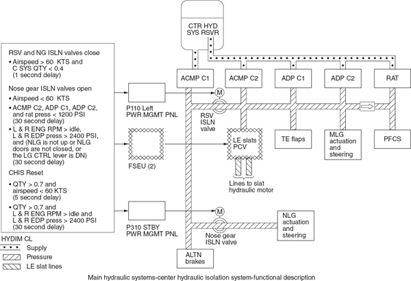
FIGURE 13-94 Center hydraulic isolation system.
Ram Air Turbine
The ram air turbine (RAT) supplies an emergency source of hydraulic power to operate the flight controls. The RAT also is an emergency source of electrical power. The RAT extends automatically in flight with a loss of hydraulic pressure in the three hydraulic systems. The RAT can also be manually extended from the flight deck.
HYDRAULIC SYSTEM FOR THE AIRBUS 380
The Airbus A380 hydraulic system consists of two hydraulic systems (green and yellow). A third hydraulic system used on previous Airbus aircraft is replaced by an electrohydraulic system made of a combination of electrohydraulic actuators (EHAs) and electrical backup hydraulic actuators (EBHAs). For the first time in civil aircraft history the A380 will use a high-pressure 5000-psi hydraulic system. The fluid remains a standard phosphate-ester type as used on most civil aircraft. The A380 hydraulic system integrates a total of eight Vickers PV3-300-31 (EDPs). The pumps are pressure-compensated, variable displacement type, and deliver 42 gpm at 3775 rpm. Their displacement is 47 ml/rev. The EDPs have a disengagement clutch, a feature not currently found on any commercial or military aircraft pump. In cases where a pump is malfunctioning while the plane is on the ground, the clutch can segregate that pump from the system. This allows the plane to be dispatched using the remaining seven pumps. The pump can only be reconnected on the ground and this is a maintenance function.
In this aircraft the electro motor pumps (EMP) will be used for ground purpose only and are located by couple in the inner pylon. Electrical systems can power the local electrohydraulic power packs. The flight control systems can be operated by electro-hydrostatic actuators (EHAs) and electrical backup hydraulic actuators (EBHAs). The brake and nose wheel steering system can be operated by local electrohydraulic generation systems (LEHGS). Figure 13-95 shows a hydraulic block diagram of the A380 hydraulic system.
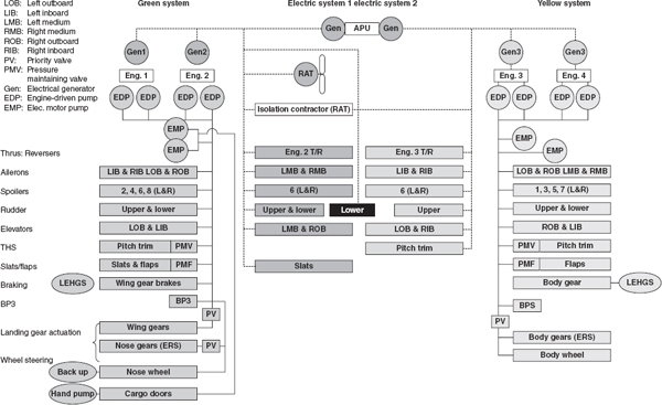
FIGURE 13-95 Hydraulic system block diagram.
The green and yellow hydraulic circuits are fully independent. Four engine-driven pumps (EDPs) per circuit pressurize the hydraulic fluid at 5000 psi in normal operation. Each circuit has a single hydraulic reservoir (RSVR). There are two EDPs per engine and each engine has one fire shutoff valve (FSOV) to supply hydraulic fluid to both EDPs on that engine. The green and yellow circuits generate hydraulic power to operate: the primary flight controls (F/CTL), the secondary flight controls, the landing gear, and the braking and steering system.
Backup Hydraulic Power
As a backup to the normal hydraulic circuits, hydraulic pressure can be locally produced for the flight controls and landing gear using local electrohydraulic power generators, supplied by the electrical network. Note that the RAT supplies only electrical power. The local electrohydraulic generation system comprises EHA and EBHA to operate primary flight controls and three LEHGS to operate braking and steering systems. Figure 13-96 shows the location of the EHAs and EBHAs.

FIGURE 13-96 Location of EHAs and EBHAs.
Electro-Hydrostatic Actuator
The EHA shown in Fig. 13-97 is a self-contained unit consisting of a servo valve, electromotor and hydraulic pump, accumulator/reservoir, and a hydraulic actuator (ram). The EHAs are a backup power source for the inboard and medium ailerons and elevators flight surfaces. During normal flight with hydraulic systems operating the EHA only have a dampening function. When there is a hydraulic failure the EHA will automatically control the flight control surfaces.

FIGURE 13-97 Electro-hydrostatic actuator.
Electric Backup Hydraulic Actuator
EBHAs are hydraulically powered in the normal mode by the aircraft hydraulic systems and electrically powered in backup mode. Four EBHAs are used to power the two rudder surfaces. The EBHAs are normally powered by the green or yellow hydraulic systems and the electric motor and pump are inoperative. In case of a failure of the hydraulic system the EBHAs automatically switch to backup mode using the integrated electric motor and pump to operate the actuator piston (ram). Figure 13-98 shows a schematic diagram of an EBHA.
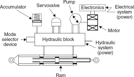
FIGURE 13-98 Electrical backup hydraulic actuator.
Local Electrohydraulic Generation System
The LEHGS is a decentralized fluid power generation system on the A380 and is used as a backup power source for braking and steering. Signals from an electronic control unit (ECU) activate a small electrically driven micro-pump, which is located close to the system to be controlled. The micro-pump provides 5000 psi (350 bar) of local hydraulic pressure over short runs of small-diameter lightweight tubing for braking and steering. The LEHGS consists of a reservoir, electric motor, pump, valves, filter, and controls. The LEHGS supplies hydraulic fluid power to the brakes and steering actuators in case the normal main hydraulic systems fail.
Auxiliary Hydraulic Power Generation
EMPs pressurize each hydraulic circuit, provided the aircraft is on the ground with all engines shut down. For the cargo doors operation, one of the EMPs in the green system operates to generate hydraulic power. An isolation valve closes to isolate the main hydraulic users from the cargo doors hydraulic circuit. A similar isolation valve is fitted to the yellow circuit for the body gear steering system, which can be pressurized by the yellow EMPs. A manually operated backup auxiliary hydraulic pump can be used to operate the cargo doors. Ground connections located in the inner pylons can also supply the green and yellow circuits with hydraulic pressure. Figure 13-99 shows the hydraulic power schematic of the A380 including the EMPs and the isolation valves.

FIGURE 13-99 Hydraulic power system schematic.
Ground Service Panel
The service panel is situated in the hydraulic bay of the A380 aircraft and integrates 11 different equipment packages, which are used to monitor and maintain the two hydraulic systems. The main components of the system include the pressure and level gauges used to monitor the reservoir air-pressurization and fluid levels, a hand pump used to refill the hydraulic reservoir, and some valves used to control the fluid and the air pressurization during the refilling operation of the hydraulic reservoirs.
Two hydraulic system monitoring units (HSMUs), one for each hydraulic circuit, control and monitor the green and yellow hydraulic circuits, respectively. They also give indication on the control and display system (CDS).
HYDRAULIC SYSTEM FOR THE BELL 214ST HELICOPTER
The hydraulic power systems on the Bell 214ST helicopter consist of three separate and independent systems: two flight-control hydraulic systems, called PC1 and PC2, and a utility hydraulic system. The two flight-control systems operate in parallel, so that if either system should fail, the remaining system will provide full control capabilities. The utility system is used only to power the cooling fan for the gearbox and transmission oil cooler. Each system is equipped with a pump, closed-circuit reservoir, hydraulic module, distribution circuit, and ground test circuit.
The hydraulic power for each system is generated by its own variable-displacement hydraulic pump. The PC1 pump is powered by the helicopter transmission, and the PC2 and utility pumps are powered by the combining gearbox. The pumps pressurize their system to 3000 psi [20 685 kPa], and they also assist the reservoir spring in pressurizing the reservoir. Each system is equipped with temperature and pressure sensors which warn the pilot of malfunctions. Protection from excessive pressure is provided by a pressure-relief valve in each system. The utility system is not discussed further, since it is very similar to the flight-control systems.
PC1 and PC2 Hydraulic Systems
Except for the power source, the PC1 and PC2 hydraulic systems are identical. The somewhat higher revolutions per minute of the combining gearbox causes the pump for the PC2 to have a slightly greater capacity for work than the PC1 pump. The PC1 and PC2 systems are shown in Fig. 13-100.

FIGURE 13-100 The hydraulic system for a helicopter—actuators not shown. (Bell Helicopter Textron.)
The hydraulic pumps are located side by side on the cabin roof in the area shown in Fig. 13-101. A schematic diagram of the PC1 system is shown in Fig. 13-102. Fluid from the reservoirs is pressurized by the pumps and passes through a check valve and a pulsation dampener, which removes surges from the pump output. The fluid next flows to the hydraulic module, first passing through a filter assembly. If the filter becomes clogged so that a pressure differential of approximately 70 psi [483 kPa] exists across the filter, a red button extends from the assembly. The filter is not designed to bypass when it becomes clogged.
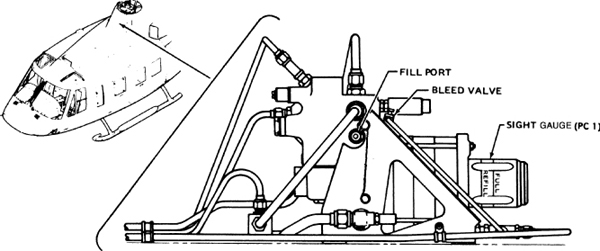
FIGURE 13-101 Hydraulic reservoir and filter assembly for a helicopter. (Bell Helicopter Textron.)
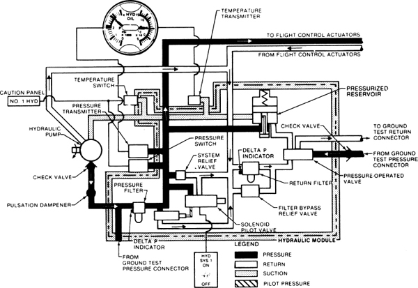
FIGURE 13-102 Schematic of a helicopter hydraulic system. (Bell Helicopter Textron.)
From the filter, fluid flows to a shutoff valve and a solenoid pilot valve. The pilot can shut down either system by opening the solenoid valve with a cockpit toggle switch. When the solenoid is energized, pressure is directed to the shutoff valve and system pressure is routed to the return line, depressurizing the system downstream of these control valves. If power to the solenoid is interrupted, the shutoff valve is closed and full system pressure is restored. Electric interlocks prevent both PC1 and PC2 from being shut down in this manner at the same time.
Excess pressure in the system is released by the system relief valve, and the relieved fluid returns to the reservoir. The relief valve begins to open at 3500 psi [24 132 kPa] and is fully open at 3850 psi [26 345.8 kPa]. The valve reseats when pressure drops to 3250 psi [22 408.8 kPa].
Downstream of the relief valve, the pressure is applied to a pressure switch, a pressure transmitter, and the reservoir pressurization line. The pressure switch operates a cockpit annunciator when pressure is lost and disables the solenoid switch for the opposite system. The pressure transmitter drives a pressure gauge in the cockpit. The reservoir pressure is maintained at 75 psi [517 kPa] by the system pressurization piston.
After passing the reservoir pressurization line, the fluid exits the module and flows to the flight-control actuators. Return fluid from the actuators is routed back to the module, through the return filter in the module, and into the reservoir. The return filter has a red button to indicate when the filter is clogged, but unlike the pressure filter, the return filter can be bypassed.
From the reservoirs, the fluid is fed back to the pumps. A temperature switch and a temperature transmitter in the line between the reservoirs and the pumps send signals to cockpit displays. The transmitter allows the pilot to monitor the fluid temperature, and the switch activates an annunciator light to warn of excessive heat in the fluid.
The system can be operated by a ground cart through the ground test connection. The quantity of fluid in the reservoirs is indicated at the sight gauge on the module, as shown in Fig. 13-101.
PNEUMATIC SYSTEMS FOR AIRCRAFT
Aircraft pneumatic systems are used primarily as emergency sources of pressure for many of the hydraulically actuated subsystems. The principle of operation for a pneumatic power system is the same, with one important exception, as that of a hydraulic power system. The air in a pneumatic system is compressible; therefore, the pressure in the system can reduce gradually from the maximum system pressure to zero pressure. In the hydraulic system, as soon as the accumulator fluid has been used and the pump is not operating, the fluid pressure immediately drops from accumulator pressure to zero pressure. The entire pneumatic system, including the air-storage bottles, can act to store air pressure. In the hydraulic system, the only pressure-fluid storage is in the accumulators, and the pressure is supplied by compressed air or gas in the air chamber of the accumulator.
The air in a pneumatic system must be kept clean by means of filters and also be kept free from moisture and oil droplets or vapor. For this reason, liquid separators and chemical air driers are incorporated in the systems. Moisture in a pneumatic system may freeze in the low temperatures encountered at high altitudes, resulting in serious system malfunctions.
Another important feature of a pneumatic system is that there is no need for return lines. After the compressed air has served its purpose, it can be dumped overboard, which saves tubing, fittings, and valves.
Pneumatic-System Description
The pneumatic system described in this section is utilized in the Fairchild F-27 aircraft. It provides power for operation of the landing-gear retraction and extension, nose-wheel centering, propeller brakes, main-wheel brakes, and passenger entrance-door retraction. The system described includes only the development and delivery of compressed air to each component or subsystem, not the actual operation of the component or subsystem. The pneumatic power in the airplane is delivered by one of two systems; the primary system or the emergency system.
The power section of the primary pneumatic system is that portion located in each engine nacelle shown in Fig. 13-103. It consists of a gearbox-driven compressor, bleed valve, unloading valve, moisture separator, chemical drier, back-pressure valve (right nacelle only), and a filter. In addition, each nacelle contains a shuttle valve, disk-type relief valve, and a ground charging connection to aid in ground maintenance or initial filling. Each power section independently supplies compressed air to the primary and emergency systems. The air in the primary system is stored in two storage bottles, and the system delivers the air for normal operation components, as required by directional valves. A schematic diagram of the pneumatic power system is shown in Fig. 13-104.
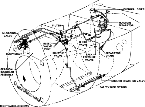
FIGURE 13-103 Pneumatic system in engine nacelle. (Fairchild Industries, Inc.)

FIGURE 13-104 Schematic diagram of pneumatic power system. (Fairchild Industries, Inc.)
A 100-in3 [1.64-L] bottle is used for the main-wheel brakes, and a 750-in3 [12.3-L] bottle is used for gear operation, nose-wheel centering, propeller brakes, and passenger-door retraction. A pressure-relief valve is installed to protect the system from excessive pressure buildup. In the air-supply tube from the large primary bottle, an air filter is installed to filter the air for the primary system. An isolation valve, which is in the tube between the large primary bottle and the smaller brake bottle, permits maintenance to be performed downstream of the valve without discharging the large bottle. On the downstream side of the isolation valve, a pressure-reducing valve is used to reduce system pressure from 3300 to 1000 psi [22 753 to 6895 kPa]. All components except the pressure gauges and the power-section components are located in the fuselage pneumatic compartment.
Air-Pressure Sources
Two views of the compressor for the pneumatic system are shown in Fig. 13-105. One compressor is located in each engine nacelle. The compressors are of four-stage, radial design, providing a delivery pressure of 3300 psi [22 753 kPa] and 2 ft3/min [5.66 m3/min] at sea-level intake pressure on a standard day. As shown in the drawings, the cylinders and pistons of the compressor diminish in size from no. 1 to no. 4. The cylinders are caused to reciprocate in the proper sequence by a cam-assembly mechanism, which rotates with the crankshaft.
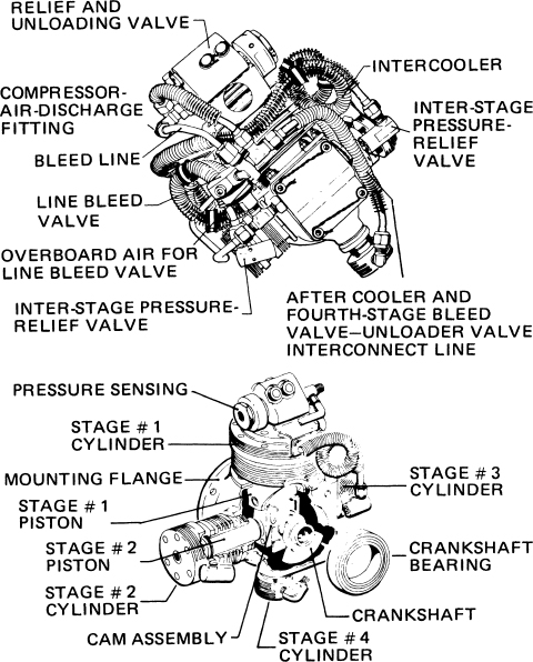
FIGURE 13-105 Four-stage pneumatic compressor.
The arrangement of the crankshaft and cam in the four-stage compressor is such that when the no. 1 cylinder is on the compression stroke, the no. 2 cylinder is on the intake stroke and the compressed air enters the no. 2 cylinder. When the no. 2 cylinder compresses, the air enters the no. 3 cylinder, which is on the intake stroke. When the no. 3 cylinder compresses, the air is delivered to the no. 4 cylinder, which is on the intake stroke. The no. 4 cylinder then compresses, and the air is delivered to the system. Thus the air has been moved from the no. 1 cylinder through the four stages to be further compressed in each stage. The interstage lines are finned to provide cooling and reduce the heat of compression.
Ducted ram air is provided for cooling of the finned cylinders and the finned interstage lines. Oil pressure from the gearbox provides lubrication for the compressor through a drilled passage in the mounting flange. Air is compressed by stages 1 through 4 of the compressor, whereas overpressure protection is provided by means of relief valves between stages 1 and 2 and 2 and 3. Compressed air from stage 4 is then routed by an intercooler line to the bleed valve mounted on the compressor.
Although the version of the F-27 being discussed makes use of an engine-driven air compressor to power the pneumatic system, other aircraft commonly make use of other power sources. Air for the pneumatic operation of controls can be provided by the engine compressor bleed air. Some aircraft use this medium-pressure air (100 to 150 psi [689 to 1034 kPa]) for operation after passing it through a pressure regulator and conditioners such as filters and driers. Other aircraft use this air to operate air turbine motors, which allows an increase in operation pressure on the pump side of the air turbine motor. Still other aircraft make use of a hydraulic motor or an electric motor to operate a high-pressure pneumatic pump. This high-pressure air is then regulated, conditioned, and allowed to flow on to the systems to be operated.
Air-storage bottles are used for emergency operations when hydraulic or pneumatic pressure sources have been lost. The bottles are normally pressurized with nitrogen, but some aircraft require the use of carbon dioxide. These bottles will power a system, normally a landing-gear extension system or a brake system, for only a brief period of time. The bottles must be recharged on the ground.
Storage Bottle
The primary air-storage bottle for the F-27 is constructed of steel with a plastic coating on the inner surface to provide a longer service life. The bottle is mounted above the fuselage pneumatic panel and is fitted with three ports. It has a volume of 750 in3 [12 290.3 cm3] and stores air at 3300 psi [22 753.5 kPa] for operating landing-gear, propeller-brake, nose-steering, and rear-door-retracting subsystems. The air pressure is reduced to 1000 psi [6895 kPa] before being routed to subsystems other than brakes. The bottle is provided with a standpipe, which permits the withdrawal of air without the danger of allowing any accumulated moisture to enter the operating systems. Accumulated moisture can be drained from the bottle by means of a drain valve located on the bottom.
Aircraft that use the pneumatic system only for emergency purposes have the storage bottles equipped with a charging valve for ground servicing and a control valve to release pressure into the system being controlled. The control valve may be an on-off type valve, where all of the bottle’s contents are released at one time, or it may be such that the pilot can control the amount of pressure being applied to a system. The on-off control is found on landing “blow-down” systems, whereas the controllable valve is typically used for brake systems.
Moisture Control
In a pneumatic system it is of the utmost importance that the air in the system be completely dry. Moisture in the system can cause freezing of operating units, interfere with the normal operation of valves, pumps, etc., and cause corrosion. It is for this reason that moisture separators and chemical driers are used in pneumatic systems.
In each compressor pressure line, a mechanical moisture separator, shown in the drawing of Fig. 13-106 is installed to remove approximately 98 percent of any moisture and/or oil that may pass from the compressor. The separator is an aluminum tubular chamber, mounted vertically on the outboard side of the right nacelle and on the inboard side of the left nacelle.

FIGURE 13-106 Moisture separator.
Two valves are installed in the bottom of the separator. An inlet air pressure of 750 psi [5171 kPa] maximum closes the drain valve, whereas the inlet valve remains closed, thus preventing air from entering the separator. When pressure reaches 900 + 150 psi [6205.5 + 1034 kPa], the inlet valve opens and allows air to flow. The inlet valve stays open as long as inlet pressure is above 1050 psi [7240 kPa]. The air entering the inlet port flows through the inlet valve seat, guide, and tube assembly and through the orifices in the retainer assembly onto the baffle. The moisture droplets are deflected by the baffle, separated from the air stream, and caused to settle at the bottom of the air chamber against the closed drain valve.
As long as the inlet air pressure remains above 400 + 150 psi [2758 + 1034 kPa], the flow of air is through the inlet port, guide, tube assembly, and outlet port. When inlet air is reduced to 0 psi, the residual air flows through the ball check of the retainer assembly and out the open drain valve, pushing the collected moisture ahead of it. The separator is equipped with a safety disk that will burst at 5800 to 6200 psi [39 991 to 42 749 kPa] as a safety measure against over-pressurization.
In the unit base is a small thermostatically controlled heater that prevents freezing of any moisture in the bottom of the air chamber. The heater is automatically operated by a hermetically sealed thermostat, located in the moisture-separator body. The thermostat closes the electrical circuit at 35°F [1.67°C] to provide heating and opens the contacts at 85°F [29.44°C] maximum. To function properly, the moisture separator must be mounted vertically with the overboard drain at the bottom.
A tubular, chemical-drier housing is installed in each nacelle downstream of the mechanical moisture separator. Each drier has an inlet and outlet port and contains a desiccant cartridge. Air is directed through this replaceable cartridge, and any moisture that the mechanical moisture separator has failed to remove will be absorbed by the dehydrating agent in the cartridge. The cartridge with dehydrating agent specification MIL-D-37 16 incorporates two bronze filters, one at each end, which allow a 0.001-in [0.03-mm] maximum-size particle to pass through.
Filters
Three sintered pneumatic filters are used, one in each compressor circuit and one in the primary circuit. The filter is a vertically mounted unit, containing a replaceable filter element of stainless steel that removes foreign matter of 10 μm or larger from the compressor output air.
Other types of filters commonly found in pneumatic systems include micronic and wire-screen filters. The micronic filter has a replaceable cartridge, whereas the wire-screen filter can be cleaned and reused. The basic construction of these filters is the same as the micronic filter units used in hydraulic systems.
Pressure-Control Valves
The bleed valve, controlled by compressor lubricating oil pressure, directs the compressed air to the compressor circuit relief valve and unloading valve. In the event the compressor oil pressure drops below 40 psi [275.8 kPa], the bleed valve will direct compressed air from the fourth stage overboard.
Pressure output from the bleed valve is routed to a relief valve in the unloading valve. The relief valve protects all components of the compressor circuit from excessive pressure buildup in the event any component downstream of the compressor malfunctions. The relief valve is set to open at 3800 psi [26 201 kPa].
The unloading valve contains a sensing valve and a directional control valve, and it directs compressor output through dehydration equipment to the system or vents the output overboard. The directional control valve, controlled by the sensing valve, opens and vents overboard when system pressure reaches 3300 psi [22 753.5 kPa] and closes when system pressure is less than 2900 psi [19 955.5 kPa].
A back-pressure valve, illustrated in Fig. 13-107, is installed in the pressure tube of the right nacelle only, to ensure that the engine-driven air-compressor output is kept at a predetermined value of 1700 + 150 psi [11 721.5 + 1034 kPa]. This is to provide and maintain a fixed back pressure of approximately 1700 psi upstream of the air-drying equipment. The back-pressure valve is similar in construction and operation to a check valve and consists of a valve seat, piston, and spring. It is installed in the outlet port of the chemical drier and is directly connected to the inlet port of a check valve. The right-engine compressor or a ground charging unit must be used for normal charging of the pneumatic system.

FIGURE 13-107 Back-pressure valve.
Poppet-type, spring-loaded, line-check valves are installed in the primary system, and each is identified by part number according to tube size. One valve is located in the inlet tube just before the point where the tube enters the primary bottle inlet port.
Another check valve is installed in the supply tube leading to the brake storage and is located on the left-center edge of the fuselage pneumatic panel. Two spring-loaded, poppet-type, line-check valves are installed in each pneumatic power system in each nacelle. One valve is installed in the outlet end of the back pressure valve; the other valve is installed in the upper outlet port of the “T” fitting.
A spring-loaded, piston relief valve is installed in the primary system. The valve is preset, safetied, and tagged by the manufacturer for a cracking pressure of 3800 + 50 psi [26 201 + 345 kPa]. It protects the primary system from excessive pressure buildup in the event of thermal expansion or compressor power system malfunction.
This relief valve is designed to relieve pressure as a metering device instead of an instantaneous on-off valve. Its rate of relief automatically increases in direct proportion to the amount of overpressure. It reseats when the pressure decreases to approximately 3400 psi [23 400 kPa].
As mentioned previously, the air pressure employed for the operation of the landing-gear, propeller-braking, nose-wheel-steering, and passenger-door-retraction subsystems is reduced from 3300 [22 753.5] to 1000 psi [6895 kPa]. This is accomplished by means of the pressure-reducing valve installed in the primary pressure supply line. This valve is mounted on the pneumatic power panel just below the isolation valve, as shown in the drawing of Fig. 13-108. The pressure-reducing valve contains dual springs and poppets, which not only reduce pressure but also provide for pressure relief of the reduced pressure should the valve fail. A cross section of the valve is shown in Fig. 13-109.
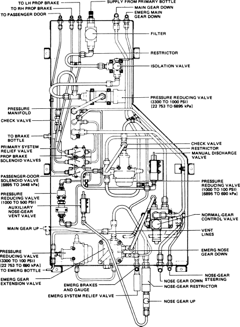
FIGURE 13-108 Pneumatic power panel.
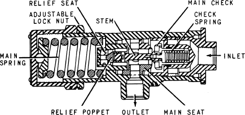
FIGURE 13-109 Pressure-reducing valve.
Additional protection is afforded the reducer relief valve by a restrictor elbow upstream of the isolation valve. The restrictor prevents excessive flow to the reducer and reducer relief valve.
Flow-Control Valves
Installed in both the right and left nacelles is a two-position, three-port shuttle valve. The valve functions to direct air to the primary system from the compressor or the ground charging valve while preventing airflow from escaping through the lines not being used for supplying air.
The pneumatic power system is provided with an isolation valve so that the air-pressure storage section of the system can be isolated from the subsystems; thus work on the subsystems can be performed without discharging the entire system. The isolation valve is a two-position (open-close) type installed on the top right side of the pneumatic panel. The valve contains a spring-loaded, poppet-type plunger, which is cam- and lever-operated. The location of the valve in the system is shown in Fig. 13-104. Connected to the valve lever is a push-pull rod-and-latch assembly, which prevents closing the pneumatic panel door while the valve is in the closed position. This arrangement eliminates the possibility of operating the airplane while the air pressure is shut off.
Selector valves for pneumatic systems are similar in construction and operation to those used for hydraulic systems.
Miscellaneous System Components
The tubing used for the pneumatic system follows the pattern described for hydraulic systems. For the high-pressure sections of the system, stainless-steel tubing is employed. This type of tubing is used where the pressures reach or exceed 3000 psi [20 685 kPa]. The steel tubing conforms to specification MIL-T-8504 and varies in size from  to
to  in [4.76 to 9.33 mm] outside diameter (OD). Steel tubing is used to carry pressurized air from the compressor to the three storage bottles, pressure gauges, emergency brakes, and brake valve and to the emergency landing-gear-selector valve. Each end of the tubing is connected by the use of MS flareless fittings. Aluminum tubing is used to carry reduced pressurized air throughout the remainder of the system. Bonding strips are used as necessary to reduce static buildup and interference.
Pneumatic Manifold
An aluminum manifold having seven ports is mounted just below and to the left of the pressure-reducing valve on the pneumatic panel. As shown in the drawing of Fig. 13-108, the manifold is connected directly to the pressure-reducing valve. The manifold receives 1000 psi [6895 kPa] air pressure and passes this air to the nose-steering, propeller-brake, landing-gear, and passenger-door subsystems through a network of aluminum tubing. The lower end port of the manifold is sealed by a threaded plug.
Primary Pressure Gauge
A direct-reading pressure gauge is connected to the primary air-storage bottle and is mounted in the pneumatic instrument panel on the right side of the crew compartment to provide a visual indication of the pressure in the primary bottle.
Ground Charging Valve
A ground charging valve is installed in both the left and right nacelles to provide a means of initial filling or ground charging the entire pneumatic system during the period when the engines are not operating. Normal ground charging is accomplished by using the right nacelle charging valve. If the system pressure is below 1000 psi [6895 kPa], the isolation valve should be closed before charging. The left nacelle charging valve should be used only during maintenance pressure checking of nacelle components or servicing the system with a dry-air source of supply.
The charging valve also acts as a protective device against an excessive rate of inlet airflow. The valve serves as a restrictor by providing a fixed orifice through which all ground-supplied compressed air must pass.
Safety-Disk Fitting
Just upstream of the ground charging valve in each nacelle is a two-port safety-disk fitting incorporating a disk-type pressure-relief assembly. The disk will rupture at approximately 4300 to 4950 psi [29 650 to 34 000 kPa], allowing air to escape through drilled passages in the retainer.
SUMMARY OF HYDRAULIC SYSTEM MAINTENANCE PRACTICES
The maintenance of hydraulic and pneumatic systems should be performed in accordance with the aircraft manufacturer’s instructions. The following is a summary of general practices followed when dealing with hydraulic and pneumatic systems.
Service
The servicing of hydraulic and pneumatic systems should be performed at the intervals specified by the manufacturer. Some components, such as hydraulic reservoirs, have servicing information adjacent to the component.
When servicing a hydraulic reservoir, the technician must make certain to use the correct type of fluid. Hydraulic fluid type can be identified by color and smell; however, it is good practice to take fluid from an original marked container and then to check the fluid by color and smell for verification. Fluid containers should always be closed except when fluid is being removed. This practice reduces the possibility of contamination. Funnels and containers employed in filling the hydraulic reservoir must be clean and free of dust and lint.
When a system has lost a substantial amount of fluid and air has entered the system, it is necessary to fill the reservoir, purge the system of air, then add fluid to the FULL mark on the reservoir. Air is purged from the system by operating all subsystems through several cycles until all sounds of air in the system are eliminated. Air in a system causes a variety of sounds, including banging, squealing, and chattering. The reservoir should be filled before the air is purged.
When cleaning filters or replacing filter elements, be sure there is no pressure on the filter. When changing hydraulic filters, wear the appropriate protective clothing and use a face shield as necessary to prevent fluid from contacting the eye. After filters have been cleaned or replaced, the system may have to be pressure-checked to locate any leaks in the filter assembly. Hydraulic fluid leaks are readily apparent because of the appearance of fluid. Large pneumatic leaks are indicated by the sound of escaping air and the feel of an airflow. Small pneumatic leaks should be located by the use of a soap-and-water solution.
Flushing a Hydraulic System
When inspection of hydraulic filters indicates that the fluid is contaminated, flushing the system is necessary. This should be done according to the manufacturer’s instructions; however, a typical procedure for flushing the system is as follows:
1. Connect a ground hydraulic test stand to the inlet and outlet test posts of the system.
2. See that the fluid in the test unit is the same type as that used in the aircraft.
3. Pump clean, filtered fluid through the system and operate all subsystems until no further signs of contamination are found upon inspection of the filters. The airplane must be raised on jacks so the landing gear can be operated.
4. Disconnect the test stand and cap the ports.
5. See that the reservoir is filled to the FULL line.
Inspections
Hydraulic and pneumatic systems are inspected for leakage, worn or damaged tubing, worn or damaged hoses, wear of moving parts, security of mounting for all units, safetying, and any other condition specified by the maintenance manual. A complete inspection includes an operational check of all subsystems.
Leakage from any stationary connection in a system is not permitted, and if any such leak is found, it must be repaired. A small amount of fluid seepage may be permitted on actuator piston rods and rotating shafts. In a hydraulic system a thin film of fluid in these areas indicates that the seals are being properly lubricated. When a limited amount of leakage is allowed at any point, it is usually specified in the appropriate manual.
Tubing must not be nicked, cut, dented, collapsed, or twisted beyond approved limits as explained previously. The identification markings or lines on flexible hose will show whether the hose has been twisted.
All connections and fittings associated with moving units should be examined for play evidencing wear. Such units should be in an unloaded condition when they are checked for wear.
Accumulators should be checked for leakage, air or gas preload, and position. If the accumulator is equipped with a pressure gauge, the preload can be read directly. Otherwise, the system pressure gauge can be used as explained previously. The accumulators should be mounted with the air chamber upward.
An operational check of the system can be performed using the engine-driven pump, an electrically operated auxiliary pump if such a pump is included in the system, or a ground test unit. The entire system and each subsystem should be checked for smooth operation, unusual noises, and speed of operation for each unit. The pressure section of the system should be checked with no subsystems to see that pressure holds for the required time without the pump supplying the system. System pressure should be observed during operation of each subsystem to see that the engine-driven pump will maintain required pressure.
Troubleshooting and Maintenance Practices
The troubleshooting of hydraulic and pneumatic systems varies according to the complexity of the system concerned and the components in the system. It is, therefore, important that the technician refer to the troubleshooting information furnished by the manufacturer.
Lack of pressure in a system can be caused by a sheared pump shaft, defective relief valve, pressure regulator or unloading valve stuck in the “kicked-out” position, lack of fluid in a hydraulic system, check valve installed backward, or any condition that permits free flow back to the reservoir or overboard. If a system operates satisfactorily with a ground test unit but not with the system pump, the pump should be examined.
If a system fails to hold pressure in the pressure section, the likely cause is the pressure regulator or unloading valve, a leaking relief valve, or a leaking check valve.
If the pump fails to keep pressure up during operation of the subsystem, the pump may be worn or one of the pressure-control units may be leaking.
High pressure in a system may be caused by a defective or improperly adjusted pressure regulator or unloading valve or by an obstruction in a line or control unit.
Unusual noise in a hydraulic system, such as banging and chattering, may be caused by air or contamination in the system. Such noises can also be caused by a faulty pressure regulator, another pressure-control unit, or a lack of proper accumulator action.
Maintenance of hydraulic and pneumatic systems involves a number of standard practices together with specialized procedures set forth by manufacturers. The technician may be called upon to replace valves, actuators, and other units, including tubing and hoses. In every case, the technician must exercise care to prevent system contamination; avoid damage to seals, packings, and other parts; and apply proper torque in connecting fittings.
Flexible hose, particularly the type with a Teflon fluorocarbon resin tubing, tends to take a set after a period of time. During the process of removing and reinstalling such hose sections, the technician should make no effort to straighten or change the shape of the hose. It is recommended that the hose be tied with a piece of cord or safety wire to hold its shape. When flexible hose is installed, the metal sleeve of the hose fitting should be held with a wrench while the nut is tightened to the fitting. Otherwise, the hose may be twisted and damaged. Twisted hose can be detected by observing the woven wire braiding or the painted lines on the outside of the hose.
Overhaul of hydraulic and pneumatic units is usually accomplished in approved repair facilities; however, replacement of seals and packings may be done from time to time by technicians in the field. When a unit is disassembled, all O-ring and chevron seals should be removed and replaced with new seals. The new seals must be of the same material as the original and should carry the correct manufacturer’s part number. No seal should be installed unless it is positively identified as the correct part and its shelf life has not expired.
When installing seals, the technician must exercise care to ensure that the seal is not scratched, cut, or otherwise damaged. When it is necessary to install a seal over sharp edges, the edges should be covered with shim stock, plastic sheet, or masking tape. Sharp-edged metal tools should not be used to stretch the seals and force them into place.
When it is necessary to replace metal tubing, the old section of tubing can be used as a template or pattern for forming the new part. In many cases, the tubing section can be procured from stock or from a parts dealer by specifying the correct part number.
The replacement of hydraulic units and tubing always involves the spillage of some hydraulic fluid. The technician should take care to see that the spillage of fluid is kept to a minimum by closing valves, if available, and by plugging lines immediately after they are disconnected. All openings in hydraulic and pneumatic systems should be capped or plugged to prevent contamination of the system. It is particularly important to see that fire-resistant hydraulic fluid is not allowed to get on painted surfaces or other material that would be damaged. Fire-resistant fluids (phosphate ester type) have a powerful solvent characteristic and should be immediately removed from any surface that may be damaged, including the skin.
The importance of the proper torque applied to all nuts and fittings in a system cannot be overemphasized. Too much torque will damage metal and seals, and too little torque will result in leaks and loose parts. In every case, the technician should procure torque wrenches with the proper range before assembling units of a system.
Additional information regarding aircraft plumbing, including plumbing for hydraulic and pneumatic systems, is provided in the text Aircraft Basic Science.
REVIEW QUESTIONS
1. What is the principal difference between a hydraulic power system and a pneumatic power system?
2. Explain how force is developed through the use of hydraulic fluids.
3. Explain the multiplication of force by means of hydraulics.
4. Explain the relationship between volume, area, and the length of stroke.
5. Name three types of hydraulic fluids and describe their basic characteristics.
6. What precaution must be taken in regard to spills on a painted surface with a phosphate ester fluid such as Skydrol?
7. Describe a hydraulic reservoir.
8. What is the purpose of a standpipe in a reservoir?
9. Why is it necessary to pressurize some reservoirs?
10. Give three methods by which a hydraulic reservoir can be pressurized.
11. What is the purpose of a hydraulic filter?
12. What are different filter elements that may be found in hydraulic systems?
13. What is the purpose of the “pop-out” indicator pin found on many filters?
14. Describe the purpose of a heat exchanger and how it functions.
15. Why is a gear-type pump described as a positive displacement pump?
16. In an axial multiple-piston pump, what causes the reciprocating motion of the pistons?
17. Describe two types of variable-delivery pumps and explain the operation of each.
18. Explain the purpose of a ram air turbine.
19. Describe the purpose of a pressure regulator.
20. How does a pressure regulator or unloading valve serve to prolong the life of the system pump?
21. List the different types of selector valves.
22. Explain how poppet valves control fluid flow.
23. Explain the operation of spool-type valves.
24. How are the selector valves in an open-center system connected with respect to one another?
25. Describe an orifice-check valve. For what purpose would such a valve be used?
26. Explain sequence valve operation and purpose.
27. What can occur if a sequence valve is not properly adjusted?
28. Under what conditions is a shuttle valve required?
29. Explain the operation and use of a hydraulic fuse.
30. Explain the operation and use of a priority valve.
31. Describe the operation of a relief valve.
32. What determines the cracking pressure of a relief valve?
33. Why is a wing-flap overload valve installed in the down line of a flap-actuating system?
34. Why are thermal-relief valves needed in certain sections of a hydraulic system?
35. Explain the principle of a debooster valve.
36. Explain the purpose of a flow equalizer.
37. What are the two functions of an accumulator?
38. Describe a piston-type accumulator.
39. What precautions should be taken before removing an accumulator from a hydraulic system?
40. What is a hydraulic actuator?
41. Describe a double-acting hydraulic actuating cylinder.
42. How does a servo actuator differ from an actuating cylinder?
43. Compare a hydraulic motor with a piston-type pump.
44. Discuss the purpose of colored markings on O-ring seals.
45. When O-ring seals are used in high-pressure systems, what devices are often necessary?
46. Compare a closed-pressure hydraulic system with an open-center system.
47. List the principal hydraulic systems in a Boeing 777 aircraft.
48. What is the function of a power-transfer unit on the 777 aircraft?
49. List the principal hydraulic systems on an A380 aircraft.
50. Name the three principal hydraulic systems for the Boeing 777 airplane.
51. What types of pumps are employed in the hydraulic power systems for the Boeing 777 airplane?
52. What systems are served by system A in the Boeing 777?
53. What is the purpose of the ground interconnect valve?
54. List the advantages of a pneumatic power system.
55. What is the difference in the principles of operation between a pneumatic system and a hydraulic system?
56. What are uses for pneumatic bottles in a hydraulic system?
57. For what functions is the pneumatic power system on the Fairchild F-27 airplane used?
58. How is the high-pressure air stored in the Fairchild F-27 pneumatic system?
59. Describe the operation of the four-stage compressor.
60. What is the purpose of the isolation valve in the F-27 pneumatic system?
61. Explain the need for dry air in a pneumatic system.
62. Describe the operation of the moisture separator.
63. What is a desiccant?
64. What is the function of the back-pressure valve?
65. How is lowered pressure obtained from the high-pressure air source?
66. Explain the use of the ground-charging valve.
67. List the principal consideration necessary when servicing a hydraulic reservoir.
68. What conditions can cause banging or chattering in a hydraulic system?
69. What conditions may cause lack of pressure in a hydraulic system?
70. What may cause the pressurized section of a hydraulic system to lose pressure?
..................Content has been hidden....................
You can't read the all page of ebook, please click here login for view all page.