

Sheet-Metal Inspection and Repair |
9 |
INTRODUCTION
Proper maintenance of an aircraft’s structural integrity can be a demanding task. Aircraft are subjected to a variety of influences, which can affect their ability to withstand the rigors of flight. Failure or potential failure of sheet-metal structural components is not always easy to identify. Once potential failure is identified, the technician must be able to evaluate the extent of the discrepancy, determine its cause, determine the proper corrective action or repair, and then implement that action.
In this chapter, the processes used to identify discrepancy through aircraft inspection are briefly reviewed. The importance of determining the cause of the discrepancy is discussed, and the techniques for repair of basic structural components are presented. In developing techniques for sheet-metal repair, both the guidelines for repair found in AC 43.13-1B & 2B and the relationship of the mechanical properties of the materials involved in the repair are discussed. In this chapter the technician will develop an understanding of how the FAA guidelines were derived and how to implement them in practical application.
SHEET-METAL INSPECTION
The process of aircraft inspection is discussed in Aircraft Basic Science. In Chap. 8 of this text, when discussing aircraft-structure design philosophies, the process of inspection as an integral part of the damage-tolerant design philosophy was identified. In 1981, the FAA issued Advisory Circular 91.56, which established guidelines for supplemental inspections for large transport-category aircraft. Whether the technician is involved with 100-h inspections, annual inspections, progressive inspections, or supplemental inspections, a knowledge of the various inspection techniques and processes is an integral part of a successful inspection.
Aircraft sheet-metal and structural components are subject to a variety of forces during their uses, as well as the weakening that comes from exposure to the environment. Simple aging also plays a significant part in the deterioration of an aircraft during its operational life. Aircraft structural inspectors must be able to identify potential problems ranging from intergranular corrosion to missing fasteners, using processes ranging from a simple visual inspection to sophisticated testing equipment.
An inspection’s scope may be general, as in a preflight inspection, or very specific, as called for by an Airworthiness Directive. The parameters used by the inspector to judge “airworthiness” may be simple, as in “cracked or not cracked” observations, or the inspector may be looking for a condition that falls within a specific range, such as clearances between certain parts. When a range is specified, the range is called a tolerance.
A tolerance may be specified in a variety of fashions, as discussed in Aircraft Basic Science. A tolerance indicates a range within which a particular attribute is considered acceptable. It is important to note that in establishing tolerance, considerations regarding the aircraft’s usage and inspection frequency are included. As a result, if the technician’s observation or measurement of a given attribute falls within the tolerance, the observation or measurement is in compliance with the tolerance. When determining compliance within a tolerance, any one observation or measurement within a tolerance is just as much in compliance with the tolerance as any other observation or measurement within the tolerance range.
Traditionally, inspections are classified as destructive or nondestructive. Maintenance by its very nature is concerned only with nondestructive testing, since destructive testing eliminates the serviceability of the part or material being tested. Although destructive testing plays a significant part in aircraft design analysis, it is not used by the technician as part of any airworthiness inspection process. Therefore, the discussion that follows is limited to nondestructive inspection techniques.
Nondestructive Testing
Nondestructive inspection (NDI) is also referred to as nondestructive testing (NDT). The philosophy of NDI is to verify the presence of certain attributes without causing the material to fail. In effect, this is an effort to validate the existence of other attributes that have been determined to identify the existence of yet others. For example, if a metal has a certain composition, hardness, and thickness (three attributes), it has been determined to have a specific ultimate tensile strength (another attribute).
Visual Inspection
The most obvious form of NDI is the visual check. This check may be performed with the naked eye or assisted by magnification. Magnification is specified in terms of power. The most frequently used magnification level employed in aviation is 10 power, designated as “10X.”
Many inspection documents begin with the instruction to clean the aircraft or the area of the aircraft to be inspected. It is, however, advisable that technicians involved in general visual-type inspections observe the aircraft before the cleaning process is begun. Clues to discrepancies may often be removed during the cleaning process, making discrepancy identification more difficult. For example, loose or improperly installed countersunk rivets disrupt the airflow around the rivet. As the air flows around these rivets, dirt in the air accumulates, leaving what appears to be a dirt trail around the rivet. It is much easier to identify these dirt trails prior to cleaning the aircraft than after the cleaning process is completed. It should be noted that a pre-cleaning inspection, although often beneficial, does not satisfy the requirements of a traditional complete inspection.
The technician can also use the sense of touch to help identify discrepant items. Running the hand or fingernails over a surface can assist the technician in finding cracks.
More detailed inspections of an area may be performed by dye-penetrant inspection, magnetic-particle inspection, X-ray inspection, fluorescent-penetrant inspection, ultrasonic inspection, and eddy-current inspection. These inspection processes are used to detect discrepancies that are not detectable using only the human senses.
Dye-Penetrant Inspection
Inspection of a metal structure is easily accomplished by means of dye-penetrant inspection. In this process, the dye penetrates any small cracks or fissures and then seeps out when a developer is applied to the joint. Thus the crack is revealed as a bright red line.
Fluorescent-Penetrant Inspection
Fluorescent-penetrant inspection can be used for detecting cracks or other flaws in a welded structure. A liquid containing a fluorescent material is applied to the part to be inspected and is allowed to penetrate cracks, laps, and other discontinuities. The part is then washed with a suitable solvent and dried, after which a developing powder is applied to draw the penetrant to the surface. Excess powder is brushed off, and the part is examined under ultraviolet light (black light). Cracks and other flaws are revealed as fluorescent markings.
Magnetic-Particle Inspection
Magnetic-particle inspection (Magnaflux) by means of magnetic powder applied to a magnetized part is an efficient, practical, and nondestructive method that will reveal the presence of tiny cracks and other flaws in a part. The surface to be examined should be reasonably smooth and free from scale, because it is difficult to find cracks in the irregular surface of the weld metal. Sandblasting is a suitable method for cleaning the surface of metal parts in preparation for the magnetic particle inspection.
Magnetization of tubular clusters and other welded joints in tubular structures is usually accomplished by means of cables wrapped in coils around the area to be inspected. The technician must follow the appropriate instructions to ensure that the magnetization is produced in the correct direction. After the inspection the magnetization must be neutralized with an alternating-current field coil.
Radiological Inspection
X-ray inspection was limited in value in the past because of the inaccessibility of many joints and the necessity of taking exposures from several angles to make certain that all defects were found. However, the results are very satisfactory and the recent developments in this field have reduced the cost and time. The use of radioactive cobalt “bombs” has made it possible to X-ray joints at almost any location.
Ultrasonic Inspection
Ultrasonic inspection techniques apply high-frequency sound waves to the part being inspected. These sound waves are reflected from the opposite side of the material or from any flaw that they encounter. Wave signals from the flaw are compared with the normal wave to determine the location and size of the flaw.
Eddy-Current Inspection
In an eddy-current inspection, electrical currents are generated in the part by means of electromagnetic waves. The electrical current flows in the part in a circular fashion, similar to the eddies observed when draining a bath tub. If a flaw exists, the indicator will show a value different from the normal response. A well-qualified operator can diagnose the response to determine the nature of the flaw.
These descriptions are condensed but provide an overview of the inspection techniques used or observed by the technician. For a more complete description of these techniques, the reader is referred to the text Aircraft Powerplants.
SHEET-METAL REPAIR
In Chap. 8, the elements of structural design for fastener joint design were discussed. AC 43.13-1B & 2B provides a series of charts derived from these design concepts that are available to the technician for use in the application of the principles discussed in this chapter.
These charts are designed to meet the “as strong as the original” criteria of the Advisory Circular, but by their nature must be very general. The FAA states in the Advisory Circular and throughout its other related publications that the technician must first comply with the provisions of the aircraft manufacturer’s Structural Repair Manual if applicable and, failing that, refer to AC 43.13-1B & 2B and MMPDS-06, Metallic Materials and Elements for Flight Vehicle Structure, as approved data for the repair design. If the repair is a major repair, the repair must be approved by the FAA, through the use of the FAA’s Form 337. Because the charts used as approved data are general in nature, it is always a good idea to have the Form 337 approved prior to beginning any repair work.
Before proceeding with any repair not covered by the aircraft manufacturer’s Structural Repair Manual, the aviation maintenance technician should have the related Form 337 approved. See Aircraft Basic Science for a discussion regarding administration and completion of FAA Form 337.
Later in this chapter, recommended repair practices are discussed. The discussion of each repair consists of three parts: (1) the techniques using AC 43.13-1B & 2B minimum criteria; (2) the application techniques recommended for use by the technician, and (3) the calculations used in developing the associated charts.
Fundamentals of Rivet Repair Design
Purpose of the Repair
The primary purpose of a repair to sheet-metal parts is to return the damaged area to its original strength. Fasteners join the patch material to the original material in such a manner that the loads applied to the original material are transferred through the fasteners to the patch material. These loads are then transmitted through the patch material across the damaged area, and then the loads are returned to the original material through fasteners. The transmission of these loads for a fastener repair is accomplished at a lap joint. A patch typically consists of two lap joints, one to pick up the load and another to return the load. Figure 9-1 illustrates the basic load-transfer concept. For most applications a single-layer patch is sufficient.
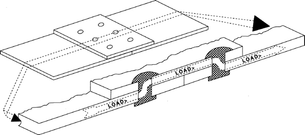
FIGURE 9-1 Preferred layout of multirow rivet patterns.
Reinforcement Plates and Plugs
The technician will frequently be required to fabricate repairs that do not alter the basic aerodynamics of the original material. In such instances a plug and reinforcement plate (sometimes called a doubler) may be used. The plug is used to maintain the surface plane and does not carry any loads. The reinforcement plate is the medium by which the loads are transferred. The actual thickness of the reinforcement plate will depend upon a relationship between the load carried and the type and number of rivets used. (Figure 9-12 shows a simple plug and reinforcement-type repair.)
Reinforcement plates are also used to provide additional strength to specific areas of a large section of an aircraft’s skin. Multi-engine propeller aircraft frequently have doublers on the aircraft’s fuselage in the plane of rotation of the propellers. These doublers provide extra strength in the areas where chunks of ice might strike the fuselage as they break loose from the propeller.
Classifications of Sheet-Metal Damage
Several aircraft manufacturers have developed classifications of damage that are used to determine the corrective action necessary to return an aircraft to an airworthy condition. Each manufacturer establishes the damage level based on the aircraft and the area of the aircraft involved. The classifications of damage are negligible, repairable, and replacement.
Negligible damage is damage that does not affect the airworthiness of the aircraft. This level of damage may be allowed to exist or can be repaired by minor patching operations. Typical of this type of damage are dents in the skin that are not cracking, cracks in areas of low stress that can be covered by a 2-in [5.08-cm] circle, and surface scratches in low-stress areas.
Repairable damage is damage that might affect the airworthiness of the aircraft and could result in a loss of function of a component or system if not repaired. Repairable damage can be repaired by the use of a patch or by the insertion of a replacement component. This might include holes in the skin and cracked or broken formers and stringers that are not significantly deformed.
Replacement damage is damage that cannot be practically repaired and where repairing is specifically prohibited. This type of damage includes extensive corrosion, parts that are twisted or warped beyond usable limits, and components requiring alignments fixtures for proper repair.
Types of Damage
Before any attempt to make a repair is undertaken, the technician should first attempt to identify the cause and nature of the damage. If the cause was the result of an external or extraordinary condition, the technician should proceed with the repair in an effort to restore the original attributes of the structure without increasing the weight of the vehicle any more than necessary.
If, however, the cause of the damage is due to normal operations, consideration needs to be given to increasing the appropriate attribute or attributes of the structure. Although strength is an important attribute, the technician must be careful not to equate rigidity with strength. In certain situations the flexibility of the structure may play an important role in determining the strength of an aircraft component. In such cases the technician should report the damage to the appropriate individuals. If the cause of the damage cannot be reasonably assumed, the technician should obtain assistance from the manufacturer in developing a repair philosophy. Any repairs not approved by the manufacturer must be approved by the FAA. AC 43.13-1B & 2B consists of approved data that may be used by the technician to develop repair and should be referred to in the document requesting FAA approval. The presence of a repair design or philosophy in AC 43.13-1B & 2B does not imply FAA approval in any specific application.
Repair-Material Selection and Interchangeability
Whenever possible the technician should use material of the same type and thickness as the original material. If this is not practical, FAA-approved aircraft manufacturer’s Structural Repair Manuals may list approved substitution materials. Table 9-1 lists generally acceptable material substitutions. In the left-hand column the table lists materials that may be substituted for and across the top lists the materials that may be used as a substitute. Each cell, the intersection of each material row and the substitute material column, has a thickness compensation factor. By multiplying the original material’s thickness by the compensation factor, the recommended thickness of the substitute material is attained. Note also that when bare material is substituted for clad material, additional corrosion protection is recommended.

General Design Guidelines
The FAA has established general rivet repair design guidelines, published in AC 43.13-1B & 2B. The guidelines include:
• Rivet replacement. In replacing rivets, the original size should be used if this size will properly fit and fill the holes. If not, the holes should be drilled or reamed for the next-larger rivet. Care should be taken when enlarging a rivet hole that the minimum criteria for rivet spacing and edge distances (discussed later in this chapter) are maintained.
• Rivet diameter. The rivet diameter for a sheet-metal joint should be approximately three times the thickness of the heavier sheet or somewhat larger for thin sheets.
• Rivet spacing. The space between rivets in a single row is called pitch, and the distance between rows of rivets is called gauge. These terms are illustrated in Fig. 9-2 The spacing between any two rivets is measured from the center of the shank of one to the center of the shank of the other. Edge distance is the distance between the center of the rivet shank and the nearest edge of the material. Edge distance is illustrated in Fig. 9-2. Note that the rivets at the ends of the rivet rows must meet edge-distance requirements in two directions.

FIGURE 9-2 Rivet pitch and gauge.
The minimum spacing for aircraft rivets specified by the FAA in AC 43.13-1B & 2B is three times the diameter of the rivet shank, except for two row applications, where the rivet spacing should be 4D. The minimum edge distance is two times the diameter of the rivet shank, as shown in Fig. 9-3. Although the minimum edge distance for rivets is given as two times the diameter of the rivet shank, it is recommended that the edge distance be not less than  times the rivet shank diameter when the rivet is of the countersunk type. This will ensure adequate strength of material along the edge of the sheet.
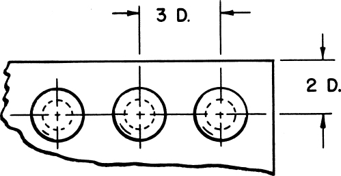
FIGURE 9-3 Minimum rivet spacing.
It is general practice to limit the maximum pitch (space between rivets in a single row) to 24 times the thickness of the sheet metal. For example, if the thickness of the sheet metal is 0.083 in [2.11 mm], 24 × 0.083 in = 1.992 in, or 2 in [50.8 mm] for practical purposes.
• Repair width. The width of the repair should be twice that of the damaged area.
General Design Assumptions
There are several basic processes that should be included in the design and application of a fastener-secured repair. After the abbreviated listing of the processes necessary to develop a design philosophy and the development of the philosophy, the concepts leading to these assumptions are discussed in greater detail.
• Stop-drill all cracks.
• Round all corners.
• Be sure the thickness of the patch material used in a repair is at least equal to that of the original material.
• Design rivet patterns so that the rivet rows are parallel with the crack(s) and perpendicular to the relative load vector.
The structural loads that relate to aircraft rivet repairs may be expressed as a single load (using vector analysis; see Basic Aircraft Science) even when there is more than one load. The general direction of the crack may be used to estimate the directional vector that represents the effective load.
The effective load vector may be assumed to be directly perpendicular to a line drawn from the beginning to the end of the crack for a single crack. If the crack is multidirectional, more than one load vector may be used. As a general rule, in establishing a rivet pattern each force vector must be compensated for on an individual basis.
• Rivet spacing should be equal in all directions (symmetrical) so that concentrations of the load are not permitted.
• The width of the patch material (Wp) should exceed the width of the damage (Wd) so that no significant loads are applied to the ends of the crack where stress risers will be created. At a minimum, the rivet pattern should allow for one load-bearing fastener at a distance equal to the pitch of the rivets on each side of the damaged area. Later in this chapter ways to safely minimize the width of the patch material below the general rule of twice the width of the damage are discussed.
• Repairs should be repairable. AC 43.13-1B & 2B refer to many minimum and/or maximum dimensional requirements. These requirements are frequently misunderstood as being the “nominal” dimension. When the technician improperly uses these dimensions as “nominal” instead of their proper interpretation (as a minimum or maximum), the potential for actually fabricating a repair that does not comply with the acceptable data of AC 43.13-1B & 2B is extremely high.
For example, assume that a technician uses the minimum edge distance of 2D for a repair using a single row of four MS20470AD3 rivets. The edge distance would be 2 ×  =
=  in. The conscientious technician locates the centers of these holes as close to in from the edge as possible. Unless the aviation technician makes a conscious decision to error in one direction only, chances are about one-half that the center punch to locate the rivet hole will actually be slightly less than the minimum acceptable edge distance. In addition, if rivets have to be removed after the installation is complete, the potential for damaging the original hole exists. If this situation exists, which requires drilling the hole to the next larger size, a simple rivet replacement is no longer acceptable per AC 43.13-1B & 2B criteria.
It is, therefore, recommended that the technician, after the minimal rivet diameter is established, lay out the rivet repair as though a rivet larger than the minimal rivet diameter were actually going to be installed. Table 9-2 shows the recommended diameters for rivet layout. The actual installation, however, would be made with the originally calculated minimal rivet diameter. Following this practice whenever possible has one major advantage. The replacement of rivets to the next-larger-size rivet provides a repair that, even if the hole is slightly mislocated originally, will comply with typically calculated or AC 43.13-1B & 2B acceptable practices.

In the examples of rivet repairs used later in this chapter, the references to “Applied” refer to the concept of designing repairs so that they are repairable.
Repair Layout Techniques
Once the basic design parameters for a repair have been established, the technician will need to develop a layout for the installation of the fasteners. Regardless of the technique used in the development of these parameters, the following layout criteria must be established before the layout process can begin: the width of the repair (W) (discussed previously), the size of the fastener hole to be used in designing the repair (D), the minimum spacing between the fasteners (S) and the edge of the repair (E), and the total number of fasteners required by the repair (Tr). Within these parameters the technician needs to determine the number of rows of fasteners and the actual fastener spacing to be used.
Note that if the repair is to be designed so that it is repairable, the diameter (D) refers to a driven rivet diameter larger than the rivet that will actually be installed. Whenever lowercase d is used, it refers to the driven diameter of the rivet that will actually be installed.
Number of Rows of Fasteners (Nr)
The number of rows (R) used in a joint is determined by the width of the joint repair (W), the diameter of the layout rivets (D), the minimum rivet spacing (S), the edge distance (E) [assumed to be 2D], and the number of fasteners (Tr) required for the repair. To determine the length of a rivet row (L), the assumed edge distance (2D) is twice subtracted from the width of the joint.
(9-1)
Substituting 2D for E yields
(9-2)
The edge distance is subtracted twice because each end of a row requires an edge distance.
Dividing the length of the rivet row (L) by the rivet spacing (S) yields the number of spaces (Ns) available within the row.
(9-3)
However, because the row begins and ends with a hole, there is one more hole required than spaces. Adding 1 to the result of the equation and then taking the integer part has the effect of algebraically rounding to the next largest number of fasteners and eliminating fractional fasteners. The result is the maximum number of fasteners in a row (Fr):
(9-4)
Substituting Eq. (9-3) for Ns yields
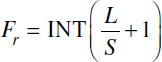
(9-5)
Substituting Eq. (9-2) for L gives

(9-6)
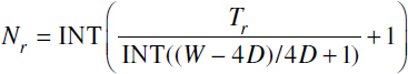
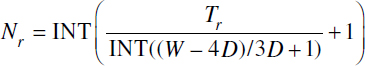
The number of rows (Nr) is then the total number of fasteners required (Tr) divided by the maximum number of fasteners in a row (Fr) rounded to the next whole number.

(9-7)
Substituting Eq. (9-6) for Fr gives

(9-8)
If the technician wishes to follow the general guideline for pitch and gauge, two calculations are required to determine the number of rows. The general guidelines state that both the pitch and gauge of fasteners installed in two rows should not be less than four times the diameter of the rivet (4D). All repairs other than two-row repairs call for pitch and gauge to be not less than three times the diameter of the fastener (3D). Unless the choice is obvious, the most efficient way to determine the desired number of rows is to perform the calculations related to the two-row spacing (4D) first. This is accomplished by substituting 4D for S in Eq. (9-8).
(9-9)
If two-row spacing (4D) will not accommodate the total number of fasteners required, then 3D spacing must be used and substituted for S, whether one or three or more rows are required.
(9-10)
In order to use the minimum number of fasteners, it may be necessary to stagger the rows so that the center of a fastener in an adjacent row is in a position perpendicular to the center of the rivet spacing between the adjacent rows (see Fig. 9-1).
Actual Fastener Spacing (Sa)
Once the number of fasteners in a row is established, it is a relatively simple matter to determine a symmetrical pattern for the rivets within a row. To develop equal spacing between fasteners in a row, divide the length of the row (L) by the number of fasteners in the row (Fr). The result is a symmetrical spacing between fasteners within the row. This process will have to be repeated for each row that varies in either length or quantity of fasteners in a row.

(9-11)
REPAIR PRACTICES
The use of the proper size and spacing of rivets and their proper installation determines whether a riveted assembly will withstand operational stresses. If any of these items is insufficient, the structure may fail, resulting in damage to the structure and injury to the aircraft occupants.
The use of specific rivet sizes and placements is dictated by the type and amount of stress placed on a structure and the size of the material being used. The following information is based on standard industry practices. For specific rivet-selection and repair procedures, consult the aircraft manufacturer’s manuals.
When a fastener joint needs to be laid out, there are a number of variables which need to be considered. These include the following:
Size of the fastener (D)
Spacing of the fasteners (S)
Total number of fasteners required (Tr)
Number of fasteners in a row (Fr)
Number of rows (Nr)
Tensile strength of the sheet with holes (Ts)
In combining all these factors into a single repair based upon the mechanical properties of the sheet and fastener materials, a number of interdependent relationships are involved. For example, the number of fasteners in a row is dependent upon the tensile strength of the sheet in the weakest row. The tensile strength of the weakest row depends upon the number of rivets in the row.
To simplify the use of these relationships in the process of designing a repair, tables have been developed for use by the technician. Simplifying the design process, however, is not without penalty. To minimize the number of tables needed to develop a repair design, as many as 10 different materials in up to 6 different forms for use in 4 different types of structural repairs are all combined into one table. To ensure that all possible combinations of these factors may successfully be used in a repair requires that the weakest of all possible combinations be used as the minimum requirement. The result is that repairs designed using these tables often require more fasteners than necessary, needlessly adding weight to the aircraft. The installation of these excess fasteners also results in increased material and labor costs.
Another difficulty with using these tables is that they were developed during the period when the majority of aircraft were designed using safe-life structural criteria. Under the safe-life philosophy, stronger—which is typically equated to more rigid—is generally considered as good or better than the original. However, modem aircraft, which require a certain degree of flexibility to accommodate the pressurized cabin, are designed using the damage-tolerant design philosophy, under which more rigid is not necessarily as good or better.
It is important for the technician to note that major repairs designed using these data must be approved via FAA Form 337 before the repair design may be considered airworthy. Although these tables are considered approved data in support of a repair design, they are not approved for all conditions. Unfortunately, the conditions under which these tables are and are not approved data are not specified in their accompanying text.
The following section of this chapter discusses the development of the repair designs using fasteners based upon the mechanical properties published in MMPDS-06. The technician, working in an environment where the general-purpose tables just described are typically considered appropriate, may wish to proceed to the section entitled “Using Repair Design Tables.”
Repair Design Using Mechanical Properties
In the discussion that immediately follows, references are made to principles established in Chap. 8. When the equations developed in Chap. 8 expressing these principles are referred to, their numbers are given for review, if necessary.
Fastener Size
The maximum load that the sheet can withstand at the rivet joint is equal to the bearing load of the sheet. If the rivet’s shear load-carrying capability (Ps) is less than that of the sheet-bearing load (Pb), the rivet will shear before the sheet. If the rivet’s shear load-carrying capability (Ps) is greater than that of the sheet-bearing load (Pb), the sheet will fail before the rivet.
Occasionally in repair design, the user must determine which is most desirable, whether the sheet or rivet should fail first. By calculating the optimum diameter of the rivet (where both Pb and Ps are equal), the technician may select the maximum strength available for each option performing only one calculation. The probability of making the calculation that results in a whole number is relatively small, so using the next-size-diameter rivet will make Ps greater than Pb, so the sheet will fail by bearing failure first. The lower rivet size will make Pb greater than Ps, so the rivet will shear first.
(9-12)

(9-13)
Multiply both sides of the equation by 4:
(9-14)
Divide both sides of the equation by d:
(9-15)
Divide both sides of the equation by (π × Fs)

(9-16)
Simplify:

(9-17)

(9-18)
EXAMPLE Use 2024-T3 clad sheet (Fb = 97 000 psi) and 2017-T4 (AD) rivet (Fs = 30 000 psi).
*WARNING: The example equations are valid only for the assumed parameters and should not be used in other applications.
For the sheet to fail first, use 4t for the diameter of the rivet. For the rivet to shear first, use 3t for the diameter of the rivet. However, in this case extreme care should be used when selecting the 3t rivet size to ensure that the diameter of the rivet will support the flight loads.
In determining the size of rivets to be used in any aircraft repair, the technician must comply with the provisions of FAA publications. These set forth the policies and regulations of the FAA relative to the repair, maintenance, and overhaul of aircraft and engines. In the repair of military aircraft, the technician should follow military standards, as set forth in technical orders and handbooks.
Rivet Spacing
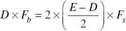
The objective of establishing a minimum edge distance and rivet spacing is to ensure that the sheet material does not tear out before bearing failure; to do this, the tearout load of the sheet must be equal to or greater than the bearing load:
(9-19)
Note that D is substituted for d, since the repair is intended to be repairable.

(9-20)
Divide both sides of the equation by t:
(9-21)
Simplify:
(9-22)
(9-23)
Add DFs to both sides of the equation:
(9-24)
Simplify:
(9-25)
Divide both sides of the equation by 2Fs:

(9-26)
EXAMPLE Use 2024-T3 clad sheet, for which Fs = 37 000 psi, Fb = 97 000 psi.
*WARNING: The example equations are valid only for the assumed parameters and should not be used in other applications.
Increasing the edge distance increases the tearout capabilities of the joint.
Determining the Number of Rivets Required per Lap Joint for a Repair (Tr)
The number of rivets required for each lap joint in any repair is determined by the strength necessary for the riveted joints. This strength is based upon two considerations. First, the shear strength of the rivets to be used must be determined. The shear on a rivet is the load that tends to cut the rivet in two parts, as shown in Fig. 9-4. Second, the tensile strength of the sheet metal must be determined. These two forms of strength, considered together, constitute the basis for determining how many rivets are needed.
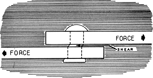
FIGURE 9-4 Shear on a rivet.
Tensile Strength of Drilled Sheet. The tensile strength of a sheet of a particular piece of material depends upon the lowest cross-sectional area of the sheet that is perpendicular to the plane in which the load is applied. The amount of load that may be applied to any solid sheet is relatively easy to determine. It is the shear strength of the material times the thickness of the material times the width of the material.
Calculating the tensile strength of a sheet of material with holes is only slightly more complex. The cross-sectional area of a sheet with holes is the width of the sheet less the diameter of each of the rivet holes affecting the cross section. The adjusted width is then multiplied by the ultimate tensile strength of the material.
(9-27)
where Wd = |
width of the damaged area |
D = |
diameter of the rivet holes sized for replacement rivets |
Fr = |
number of rivets in the densest row [the row that has the greatest number of rivets; see Eq. (9-6)] |
In situations where more than one pattern of rivet holes exists (i.e., multiple rows of rivets with a different number or rivets in one or more rows) the row with the least cross-sectional area (i.e., the most rivets) is used to determine the tensile strength of the rivet joint sheet.
Note that the actual width of the patch would exceed that of the damaged area. However, by using the damage width at this point, the minimum tensile strength of the sheet for both a splice and a patch may be calculated by a single formula.
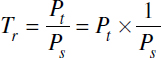
Number of Fasteners Required per Lap Joint (Tr). The number of fasteners required to transfer the load from one sheet to another is equal to the tensile load of the sheet (Pt) at the joint divided by the shear load for each fastener (Ps) or the bearing load of the sheet (Pb), whichever denominator is least. This results in the highest number of rivets required to sustain the load.

(9-28)
or

(9-29)
Since the technician, when calculating the number of rivets required, is concerned with repair, as opposed to original design or replacement, the tensile load of the sheet (Pt) is calculated based upon the condition of the original material. The original material is used because the load that is required to be transferred is equal to the existing load applied during the aircraft’s operations.
In the following equations, the original material is assumed to be solid (i.e., without existing holes). Because the presence of existing holes would lessen the load-carrying capability of the original sheet, calculating Pt based upon a solid sheet errs on the conservative side when calculating the number of rivets required. As a result, for repair Eq. (8-30) is used. If the nature of the repair requires the technician to make more exacting calculations, the technician should substitute Eq. (9-27) for Pt.
To minimize the number and complexity of the calculations required of the technician, it is suggested that the values of Ps and Pb be calculated first. Then the equation with the lower of the two values should be used. Because they are in the denominator of the equation, the higher number of rivets (Tr) will be the result of using the lower value.
For completeness of this discussion, both calculations are derived next. For Pt/Ps, the equation is
(9-30)
(9-31)
Note that D is substituted for d in Eq. (8-28) because the repair is assumed to be designed to be repairable.
Equation (9-31) simplifies as follows:

(9-32)
or

(9-33)
Dividing 4 by π yields

(9-34)

(9-35)
Simplifying Eq. (9-35) yields

(9-36)
Remember that this is the number of rivets required to transfer the load from one piece of material to another at a lap joint. So, the actual number of rivets required for a typical patch with two lap joints would be twice the number calculated here.
Width of Patch Repairs
The width of a patch must be wider than the width of the damaged area if material of the same type and thickness is used for the patch. This is because the tensile-strength capability of the damaged area is the width of the area times the thickness of the material. The tensile-strength capability of the patch is the width of the patch less the diameters of the fastener holes times the thickness of the material. So the width of the patch must exceed the width of the damaged area by at least the sum of the diameters of the fastener holes plus the rivet spacing for those fastener holes outside the damaged area. This value may be easily calculated by the technician if the additional weights caused by a repair are to be minimized. However, the general rule of thumb previously mentioned of twice the damaged width is sufficient to meet structural requirements.
Using Repair Design Tables
Tables have been prepared to designate the number or rivets necessary to restore the strength to a given section of sheet aluminum alloy when using 2117-T3 rivets. Table 9-3 is an example for rivets from to  in [2.38 to 6.35 mm] in diameter and aluminum-alloy sheet thicknesses from 0.016 to 0.128 in [0.406 to 3.25 mm]. When such tables are available, it is a simple matter to determine the number of rivets necessary for any particular repair.
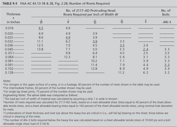
If it is desired to repair a 2-in [5.08-cm] break in a sheet of 0.025-in [0.635-mm] aluminum-alloy skin on an airplane, the number of rivets would be determined as follows:
1. Select the size of rivet. Since the riveted sheet is 0.025 in [0.635 mm] thick, the rivet diameter must be at least three times this amount. This requires a rivet of at least 0.075 in [1.91 mm] in diameter. The next larger standard rivet is in [2.38 mm]; hence this is the size to be used.
2. Refer to Table 9-3 and note that when the thickness t of the sheet is 0.025 in [0.635 mm], the number of -in [2.38-mm] rivets should be at least 8.6 per inch of width W of the repair. The break to be repaired is 2 in [50.8 mm] long; hence 17.2 rivets are required. Therefore, 18 rivets are used on each side of the repair to restore the required strength.
Remember that this is the number of rivets required to transfer the load from one piece of material to another at a lap joint. So, the actual number of rivets required for a typical patch with two lap joints would be twice the number calculated here.
Although the minimum edge distance for rivets is given as two times the diameter of the rivet shank, it is recommended that the edge distance be not less than times the rivet shank diameter when the rivet is of the countersunk type. This will ensure adequate strength of material along the edge of the sheet.
The layout for the repair discussed here could look like the one shown in Fig. 9-5. There can be variations in the design of a layout, provided the basic requirements of edge distance, rivet size, and rivet spacing are met. Observe in the illustration that rivets are spaced at a greater distance than the minimum.

FIGURE 9-5 Layout for a typical rivet repair.
Load Transmission: Multirow Rivet Patterns
So far the discussion regarding rivets and load transfer has assumed that each rivet in the repair transfers an equal load. However, in application, the rivets in each row of rivets actually transfer a different load. The first row of rivets transfers the most load, with decreasing loads being transferred by each subsequent row of rivets.
From previous discussions, it is known that the rivets of an appropriately designed joint will not shear under the design load. Therefore, each rivet is capable of and actually transfers its maximum capabilities until the load remaining to be transferred is less than the capabilities of the rivet. Figure 9-6 indicates this load-carrying sequence.
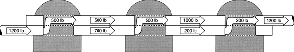
FIGURE 9-6 Transfer of load in multiple-row applications.
The first load transfers its maximum transfer capabilities, which is the cross-sectional area of the rivet times the load applied (Ltr1 = ND × Lr1). The remaining load is the original load less the load transferred by the first row of rivets (Lr2 = Lr1 – Ltr1). The load applied to the second row of rivets is therefore less than the load applied to the first row. The load actually applied to the second row of rivets is the cross-sectional area of the rivets times the number of rivets times the actual load applied. The remaining load is the load applied to the second row of rivets less the actual load transferred. This continues until the entire load is transferred.
Stacked Doublers
The actual load-transfer process, when row transfer is considered, allows the technician to do some interesting things in an effort to save weight. Typically, the technician uses patch material of equal or greater thickness than the original. In repair applications where the repair is required because of the structural failure of a component, the repair material always requires a strength equal to or greater than the original. The weight-conscious technician may use his or her knowledge of load transfer to save weight in the design phase of the rivet repair.
The patch material needs to carry only the actual load that is transferred. Therefore, the thickness of the patch material required at the first row needs to be only thick enough to support the load Ltr1.
For the second-row transfer, the patch material needs to be capable of carrying the load previously transferred (Ltr1) plus the load transferred by the second row of rivets. The same is true for all the rows involved in the rivet repair.
The weight-conscious aviation technician has basically two options available to take advantage of this load-by-rivet-row transmission. The steps (increases in material thickness) may be fabricated by various metal-removal techniques or by “stacking” pieces of different-thickness materials upon each other. The combination of material pieces indicated in the last option is frequently referred to as stacked doublers, which are shown in Fig. 9-7.
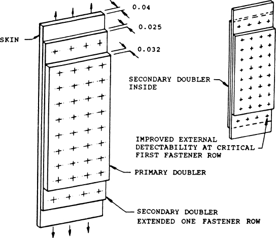
FIGURE 9-7 Stacked doubler.
Loads Applied to Multiple Planes in Shear
The earlier discussion regarding load calculations and their application needs to be expanded in order to include the use of multiple sheets of material to carry applied design loads. Loads applied to a joint may be applied in a single plane or in multiple planes. When more than two sheets make up a fastener joint, there are multiple shear planes. Figure 9-4 shows the double shear experienced by a rivet joint that has two shear planes.
Multiple planes result in a sharing of the applied loads by the materials involved. The benefit in multiple-plane load applications is that the total load is divided between the multiple planes and, as a result, the mechanical properties of the materials associated with each load plane do not need to be as large as would be required in a single-load-plane application. The sum of the load-carrying capability of each load plane is the total load-carrying capability of the joint.
There is, however, a negative impact of multiple-plane load application. Since the load planes are adjacent, separated only by one material thickness, a portion of the load applied to one plane carries over into the next plane. The thicker the material, the less this effect. In most materials handbooks, including MMDDS-06, the shear strengths for two planes are established. These two-plane shear strengths are significantly lower than single-plane shear strengths; therefore, the technician should consult these handbooks for the proper values. The double shear strengths are, however, typically much more than half the single-shear strengths, making the advantages of multiple-plane loads worthy of consideration in some applications.
Determining Design Loads
As discussions regarding rivet-repair design are put into practice, the technician may find it useful to determine the aircraft’s design loads. This may be accomplished by analyzing the aircraft’s original rivet diameter in relation to the type and thickness of the material used. When applying this technique in rivet-repair design, however, the technician should be assured that the original design loads are sufficient. If the damage causing the need for a repair is nonload related, such as holes caused by a foreign object, this process will provide the needed data. However, if the cause of the repair was insufficient load transmission under normal flight operations, the technician should consult the aircraft manufacturer.
To determine the design load, begin by finding the rivet’s diameter and material type. The rivet’s material may be determined by examining the rivet head. The thickness must also to be determined. If the material type cannot be determined, the aircraft manufacturer must be consulted. The maximum shear strength of the rivet needs to be calculated [refer to Eq. (8-28)]. The maximum bearing load and tensile loads of the sheet material are calculated [refer to Eqs. (8-34) and (8-30), respectively]. Determine the number of rivets per inch. This is most accurately accomplished by counting the number of rivets over a lengthy span and dividing the number of rivets by the number of inches in the span.
The three loads that determine a rivet pattern are the tensile load carried by the material, the bearing load applied to the material, and the shear load placed on the rivet. By revising some of the equations previously developed and assuming the other loads are maximized, the technician can determine the maximum of any of the individual loads.
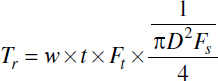
The equations for these relationships are shown next. For the technician who might wish to verify these equations, the equation from which each was derived is noted. In these equations w is assumed to be the width of the joint, t = the thickness of the material, d = the diameter of the driven rivet, and Tr = the number of rivet.
To solve for the maximum tension load Ft(max) with Fb(max) at maximum, we use Eq. (9-36):

Multiplying both sides by DFb(max) yields
(9-37)
Dividing both sides by w gives

(9-38)
To solve for the maximum sheet-bearing load Fb(max) with Ft(max) at maximum, we begin with Eq. (9-37):
Dividing both sides by TrD gives

(9-39)
To solve for the maximum tension load Ft(max) with Fs(max) at maximum, we begin with Eq. (9-34):

Multiplying both sides of the equation by D2Fs(max) yields
(9-40)
Dividing both sides by 1.27wt gives

(9-41)
To solve for the maximum shear load Fs(max) with Ft(max), at maximum, we use Eq. (9-40):
Dividing both sides by TrD2 gives
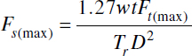
(9-42)
To solve for the maximum shear load Fs(max) with Fb(max) at maximum, we use Eq. (9-18):

Multiplying both sides by Fs(max) gives
(9-43)
Dividing both sides of the equation by d simplifies the equation to
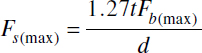
(9-44)
To solve for the maximum sheet-bearing load Fb(max) with Fs(max) at maximum, we use Eq. (9-43):
Dividing both sides of the equation by 1.27t yields

(9-45)
In some applications, the calculated load may exceed the ultimate strength of the material as determined by the mechanical properties. Since this is never the case in a properly designed aircraft, the maximum of any of the mechanical properties is that property’s ultimate strength. Therefore, if the mechanical property being calculated exceeds its mechanical properties, the ultimate strength should be used in all subsequent equations.
Using the calculated maximums or the materials’ related ultimate strength, whichever is least, and repeating the calculations allows the technician to approximate the design load factors. The more often these calculations are made the closer the approximation will become.
RIVET-REPAIR DESIGN
For each step in the design process for rivet repair, three procedures are described. The first, indicated as “General” (see below), follows the general guidelines established by the FAA and uses minimums as the design criteria. The second procedure, marked “Applied,” uses the FAA minimums but is designed so that the rivet layout is repairable. The third technique for rivet layout, marked “Calculated,” shows the results if the repair was designed using the calculations previously discussed.
Before proceeding with an explanation regarding how to use this information, the information provided in Fig. 9-8 should be reviewed. The strength data provided in Fig. 9-8 are accurate but not complete. In area (B) of Fig. 9-8 the strength comment in the upper left corner is limited only to the second row from the left and the row of rivets to which the arrow is pointing. The strength of the sheet is determined by the strength at its weakest point, which in this case is not the rows to which the arrow is referring. The relative sheet strength of the (B) joint is 66.7 percent, which results from the 3D spaced rivets.

FIGURE 9-8 Riveted sheet-metal splices.
Splicing of Sheets
Figure 9-8, which is a duplication of Fig. 2.18 in AC 43.13-1B & 2B, is an example of how sheet-metal materials might be spliced. The technician should note the difference between a “splice” and a “patch.” A splice is the mating of two or more pieces of material so that the load is transferred from one material to another. A patch consists of two or more lap joints, where the loads applied to original material are first transferred from the original material to a doubler (which may be the patch material) and then from the doubler back to the original material. In aircraft design, a transition doubler may be a stinger, rib, or flange.
When splicing sheets, the splice should be designed as illustrated in the following example. The example makes the following assumptions:
Width of sheet (length of splice): W = 12 in [30.48 cm]
Sheet material: |
2024-T3 Alclad sheet 0.032 in [0.813 mm] thickness UTS = 59 000 psi UBS @ 1.5D = 97 000 psi USS = 37 000 psi |
Rivet material: |
AN470AD rivets 2117 = T4 USS = 30 000 psi |
Determining the Rivet Diameter
In AC 43.13-1B & 2B, para. 2.99h, the discussion regarding rivet size uses the phrase “approximately three times the thickness of the thicker sheet.” This relationship between the thickness of the sheet and the diameter of the rivet is not a minimum. If a technician uses the calculations previously discussed and these calculations result in a rivet diameter slightly smaller than “three times the thickness of the thicker sheet” of material, the technician may elect to use the smaller-diameter rivet.
General. Select the rivet diameter approximately three times the sheet thickness. Thus, 3 × 0.32 = 0.096 in [2.44 mm]. Since the next standard size greater than 0.096 in is  in, use -in [3.175-mm] 2117-T4 (AD) rivets. Unless design criteria dictates otherwise, when the calculated rivet diameter exceeds that of a standard-size rivet, the next largest standard-size rivet is used.
Applied. The minimum diameter of the rivets to be installed is in [3.18 mm], but for the layout work that follows the criteria for a rivet two standard sizes over (or in [4.76 mm]) will be used for the rivet layout.
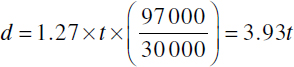
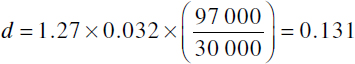
Calculated. By applying Eq. (9-18), which is d = 1.27t(Fb/Fs), the technician may calculate the diameter of the rivet required.
Although, when using the AC 43.13 charts, the rivet-diameter selection was in [3.18 mm], using a  -in [3.97-mm] rivet would better meet the criteria when considering the mechanical properties of the materials involved. However, the calculated rivet size is only 0.006 in [0.15 mm] over the diameter of the -in [3.18-mm] “charted” rivet diameter, and if the driven diameter of the charted rivet is considered, a difference of 0.002 in [0.05 mm] between the calculated and charted rivet exists.
Since the mechanical properties of the materials used for the repair do not reflect a safety factor, it is fairly safe to assume that the -in [3.18-mm] rivet is capable of handling the loads involved. The technician could, however, calculate the design load applied to the repair area by examining the existing rivet diameters and their spacing, as indicated in Eqs. (9-37) through (9-45).
In continuing this example, the -in [3.18-mm] rivet will be assumed to meet the design load criteria.
Determining the Number of Rivets
When determining the number of rivets, the ability of the rivets to withstand a shear load is equated to the ability of the rivets to withstand an equal bearing or tensile load, whichever is least.
General. Determine the number of rivets required per inch of width W from Table 9-3. The number of rivets per inch equals 6.2; hence the total number of rivets required is 12 × 6.2 = 74.4, or 75 rivets. Unless design criteria dictate otherwise, when the number of rivets exceeds a whole number, the number of rivets is always rounded up. The technician should note here that this example deals with a splice. A splice differs from a patch repair, which must have twice the number of rivets because it must first transmit the load to the patch and then return it to the skin on the other side of the damaged (or removed) area.
The technician may apply footnote (c) of Table 9-3, if appropriate. For single-lap joints, 75 percent of 74.4 rivets, or 56 (when rounded), may also be successfully used.
Applied. Since the diameter of the layout -6 rivets is larger than the -4 rivets, the -6 rivets are capable of withstanding greater shear forces. Because -4 rivets will be initially installed and their load-bearing capability is less than that of an equal number of -6 rivets, the number of rivets used in the repair should be that calculated in the general procedure. A review of Table 9-3 verifies this fact. Note that for a given thickness of material, as the diameter of the rivet increases, the number of rivets decreases.
Calculated. The load-carrying capability of the sheet material is generally assumed to be the load applied to the repair area. However, the technician might wish to develop a maximum-load applied criteria by analyzing the aircraft’s existing rivet pattern and using these concepts to calculate the applied load. If this process and the general procedure are followed (i.e., additional spacing is not added to the rivet pattern in order to accommodate repairs to the repair), this will usually result in a duplication of the existing rivet pattern. For the purposes of this example, the load-carrying capabilities of the original material will be assumed to be the applied load.
When using this technique, the technician should take care in determining the cause for the repair. If rivet shear (as a result of flight loads) is the cause, the existing rivet pattern is insufficient and should not be used to determine applied loads. This also applies to the general guidelines established by the FAA in AC 43.13-1B & 2B.
By using Eq. (9-34), if the shear strength of the rivet [see Eq. (8-29)] is greater than the bearing strength of the sheet [see Eq. (8-35) or Eq. (9-36) if the opposite is true], the number of rivets required may be calculated. In this example the rivet shear strength is 389.1 lb and the bearing strength of the sheet at a -in [3.18 mm] hole is 398.8 lb. When doing these calculations, the drilled-hole diameter rather than the rivet’s predriven diameter must be used. Because the shear strength of the rivet is less than the bearing strength of the sheet, Eq. (9-34) is used.
Using Eq. (9-34) to find Tr, the number of rivets required is 58. If this was a patch-type repair, twice as many rivets per side of the joint, or 116 rivets, would be required. Remember, when doing these calculations, the drilled-hole diameter and not its predriven diameter must be used.
Determining Rivet Spacing and Layout
In this step, the layout is accomplished based upon an equalization of shear strength to the bearing or tensile capabilities of the sheet.
General. Using the minimum-diameter rivets of in [3.18 mm] to establish a rivet pattern, to find the number of rows required, the edge distance, which is a constant, 2D, must be subtracted twice from the length of the splice. This results in an available rivet-row width of 11.500 in [2.92 cm]. The number of rivets that may be placed in a row is one more than the row length divided by the rivet spacing used. This is because the row length both starts and ends with a rivet. In the case of 3D rivet spacing, that means 31 rivets per row maximum. 4D spacing would accommodate 24 rivets per row maximum. Since 4D spacing is used only in two-row applications and 75 rivets are needed, the splice may not be accomlished in two rows. This is also the case even if footnote (c) (Table 9-3) is applied and 56 rivets were used to accomplish the repair. Therefore, 3D spacing must be used.
Using a 3D pitch, based upon 75 rivets, there would be 25 rivets per row with a pitch of 0.46 in [11.68 mm], edge distance of 0.250 in [6.35 mm], and a gauge of 0.375 in [9.53 mm]. Figure 9-9 shows this layout.
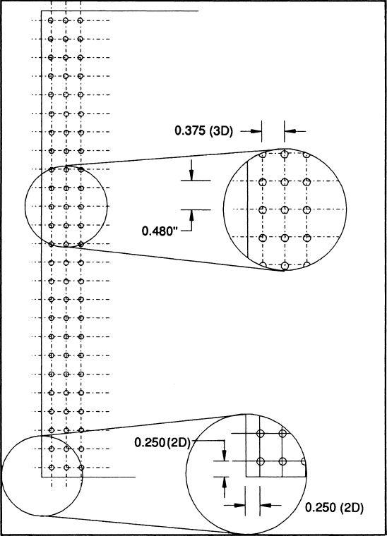
FIGURE 9-9 A 75-rivet layout using 3D spacing.
Based upon a 3D pitch with 56 rivets, there would be three rows of rivets, two each with 19 rivets and a third with 18 rivets. Figure 9-10 shows this layout. Whenever multiple rows are used in a rivet pattern and the rows contain different numbers of rivets, one of the rows with the lesser pitch, or the most number of rivets, should be nearest the edge of the material.

FIGURE 9-10 A 56-rivet layout using 3D spacing.
Applied. This step of the rivet-layout procedure is the step that makes the applied process different from the general process. In this section the edge distance and rivet spacing are calculated to comply with the minimum diameter of a rivet two sizes larger than was previously determined. In applying the “repairable repair” concept, the layout is based upon the edge distance and rivet spacing required by a rivet two standard sizes larger, or  in [9.53 mm].
The edge distance for a -in [9.53-mm] (-6) rivet is  in [19.05 mm]. The rivet spacing may be either 3D or 4D, so it needs to be calculated twice. The 3D spacing is 0.281 in [7.14 mm]. The 4D spacing is 0.375 in [9.53 mm].
To find the number of rows required, the edge distance, which is a constant 2D, needs to be subtracted twice from the length of the splice. This results in an available rivet row width of 11.625 in [2.95 cm]. The number of rivets that may be placed in a row is then one more than the row length divided by the rivet spacing used, since the row length both starts and ends with a rivet. In the case of 3D rivet spacing, that means 42 rivets per row maximum. 4D spacing accommodates 32 rivets per row maximum. Since 4D spacing is used only in two-row applications and 75 rivets are needed, the splice may not be accomplished in two rows. Therefore, 3D spacing must be used.
However, if footnote (c) of Table 9-3, is applied, the number of rivets required is 75 percent of 74.4, or 56 (55.8) rivets, so a rivet pattern of two rows may be used.
Since the applied section uses larger rivets for layout, the rivet spacing will be increased using AC 43.13-1B & 2B guidelines, so the spacing will exceed the minimums established by the Advisory Circular when -4-in-diameter rivets are installed.
Figure 9-11 shows a layout that is acceptable for -6 rivets and accommodates 75 rivets.
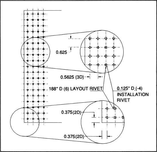
FIGURE 9-11 An acceptable layout for -4 rivets, using -6 spacing.
Calculated. Using Eq. (9-26), the technician can calculate the proper edge distance for this particular application. These calculations result in a suggested edge distance of 0.217 in [5.51 mm]. Since this distance is less than the 2D recommended by AC 43.13-1B & 2B, the 2D distance should be used.
At this point the technician should take special note that the terms edge distance and rivet spacing as used in the general and applied processes refer to a distance measured from the center of the rivet hole. In calculating rivet spacing and edge distances, the definition of these terms must be altered.
In the splice example given previously, if flush rivets are used, it is recommended that an edge distance of D (rivet diameter) be used. For universal-head rivets, an edge distance of not less than 2D is satisfactory.
In splice applications the width for the rivet layout is equal to W. However, in the case of a patch, the width of the rows should be twice the width of the damaged area. The technician should also keep in mind that when adding holes to a sheet of material, such as an aircraft skin, the tensile load-carrying capability of the material is reduced [see Eq. (9-27)].
Repairs for Small Holes
Small holes in sheet-metal skin may be repaired by means of a patch plate or a flush patch if the damage does not affect ribs or other structural members. The rough edges of the hole may be smoothed with a file, cut away with a hole saw, or punched with a chassis punch.
The patch for a small hole can be riveted to the outer surface of the skin, or it may be made flush, as shown in Fig. 9-12. In either type of patch the number of rivets should conform to the patterns shown in Fig. 9-12, which illustrates patches for 1-, 2-, and 3-in [2.54-, 5.08-, and 7.62-cm] round holes.

FIGURE 9-12 Flush patch for a small hole.
Where a flush patch is used, the patch is placed on the inner side of the skin. A plug is cut to fit the hole and is riveted to the patch. The rivets should be of the flush type, as previously described in this chapter.
Repair design of small holes using a patch is similar to the splice except for three considerations. First, W is the diameter of the hole in the original material. Second, because this is a patch, the number of rivets required for the entire repair is at least twice the number required for the splice. Note that the outside diameters of the circular patch doublers are all greater than two times the diameter of the hole. The rivets should be equally spaced around the hole.
Third, no rivet should be placed in a line perpendicular with the vector that represents the application of the load. Rivets on a plane perpendicular to the application of the load will neither pick up nor deposit a load.
Replacement of Skin Panels
In cases where damage to stressed skin has occurred over an extensive area, it is often necessary to replace an entire panel. The original panel is removed by carefully drilling out the rivets at the seams. A new panel of the same material and thickness is cut to the same size as the original. The rivet pattern at the seams must conform to the original pattern. In cases where a portion of a panel is replaced and different rivet patterns are used on the opposite edges of panels, it is best to copy the pattern of the stronger seam. Before a damaged panel is replaced, the interior of the structure must be inspected carefully. All damaged ribs, bulkhead, or other structures must be repaired before replacing the skin panel.
Repairs of Sheet-Metal Ribs
Typical repairs for formed sheet-metal and built-up ribs are shown in Fig. 9-13. In making repairs of the type shown, the technician must use the correct number of rivets of the proper size and material. The replacement material and material used in making reinforcements must be of the same type as that used in the original structure. Furthermore, the material must have the same heat treatment as the original. The thickness of the repair material must be the same or greater than that of the original.

FIGURE 9-13 Repairs for sheet-metal ribs.
Repairs for formed sheet-metal rib-cap strips are illustrated in Fig. 9-14. The repairs shown are indicative of the types of repairs required; however, many different types of repairs can be made as long as the strength and durability are adequately restored.
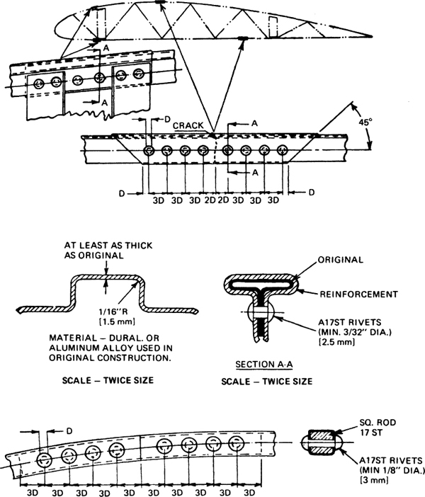
FIGURE 9-14 Repairs for metal rib-cap strips.
Stringer and Flange Splices
Splices for stringers and flanges are shown in Fig. 9-15. The original material is shown unshaded; the reinforcing material is shaded. Remember that stringers are the longitudinal supporting members to which the skin of the fuselage or wing is attached. The stringers are attached to the bulkheads or beltframes (formers), which are principal structural members of the assembly and are designed to take both compression and tension loads. Therefore, these riveting principles must be followed:

FIGURE 9-15 Splices for stringers and flanges.
1. To avoid eccentric loading and buckling in compression, splicing or reinforcing parts are placed as symmetrically as possible about the centerline of the member. Attachment is made to as many elements as necessary to prevent bending in any direction.
2. So that reduction of strength under tension of the original member is avoided, the rivet holes at the end of the splice are made small—that is, not larger than the original skin-attaching rivets—and the second row of rivets is staggered back from the ends.
3. To prevent concentrating the loads on the end rivet and the consequent tendency toward progressive rivet failure, the splice member is tapered at the ends. This also has the effect of reducing the stress concentration at the ends of the splice.
4. When several adjacent stringers are spliced, the splices should be staggered if possible.
5. The diameter of rivets in stringers should be between two and three times the thickness of the leg but should not be more than one-quarter its width.
Repairing Cracked Structures
Methods for repairing cracked structures are shown in Fig. 9-16. This illustration shows repairs at the intersection of ribs and spars at both the leading edge and the trailing edge of a wing or other airfoil. Reinforcing plates must be of the same alloy and approximately  times the thickness of the original material. In every case where cracks are repaired, the cracks should be stop-drilled before installing any reinforcements. Stop-drilling can be defined as the process of drilling a small hole at the extreme end of a crack to prevent the crack from progressing farther into the material. The hole at the end of the crack removes the sharp stress-concentration area.

FIGURE 9-16 Repairs for cracked structures.
The condition causing cracks to develop at a particular point is stress concentration at the point combined with the repetition of the stress, as would occur with vibration. Stress concentrations are caused by nicks, scratches, or incorrect design factors. Complete failure of wing structures has been caused by stress concentrations where material has been cut to form a notch. In all repairs, the technician must make sure that material is not cut to form a sharp angle between two edges and that where two edges come together to form an angle, the material is rounded (“radiused”) to a radius sufficient to prevent stress concentrations. The radius should be made as smooth as possible.
Members of aircraft structures that have developed cracks at fittings can be repaired as shown in Fig. 9-17. The treatment of cracks in these repairs is the same as described previously.

FIGURE 9-17 Repairs for cracks at fittings.
Structural Repair Manual Repairs
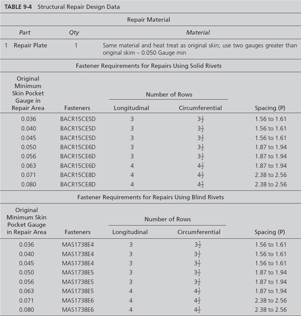
All certificated aircraft will have a structural repair manual (SRM) that is prepared by the manufacturer and approved by the FAA. The SRM will contain repair procedures that the technician can perform without contacting the original equipment manufacturer (OEM). If the damage exceeds the damage limitations in the SRM the technician should contact the engineering department of the company or the OEM. Figure 9-18 shows a complex repair that uses multiple doublers and a filler to repair damage to the aircraft skin. Figure 9-19 shows a flush skin repair that consists of multiple repair parts. Figure 9-20 illustrates a SRM repair of a cracked beam, and Figure 9-21 shows a SRM fuselage skin repair for a transport aircraft. Note that the technician does not have to calculate rivet spacing, number of rivets, material thickness, and rows of rivets. This information is all contained in Table 9-4. The technician determines the thickness of the original fuselage skin and based on this information he/she determines the thickness of the repair doublers, rivet spacing, number of rows, type of rivets, and rivet size. The technician will use the information in Figure 9-21 to repair the damage to the aircraft.

FIGURE 9-18 Skin repair using mulitple repair parts.

FIGURE 9-19 Flush skin repair with multiple repair parts.
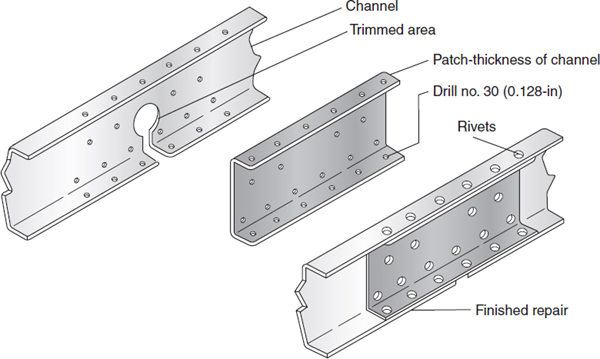
FIGURE 9-20 Repair of cracked beam.

FIGURE 9-21 External repair of fuselage.
Chem-Milled Skin Repair
A chem-milled structural member varies in thickness from end to end or side to side. Therefore, repair requires a procedure slightly different from standard procedures. The repair material must be as thick as the thickest part of the chem-milled structure. The repair material is applied to the thickest part of the damaged member, using normal riveting procedures. Shimming is used to fill the gap between the repair material and the thin part of the member. The shim material is secured with rivets that pass through the damaged part, the shim material, and the repair material. Figure 9-22 shows a typical chem-milled skin repair.
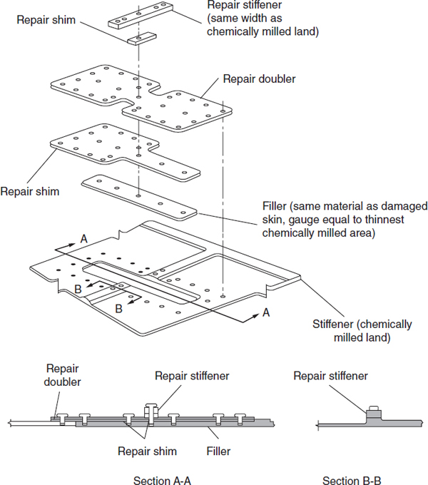
FIGURE 9-22 Typical chem-milled skin repair.
Special Repairs
Where specific instructions for sheet-metal structural repairs are not available in the manufacturer’s manuals, which should always be the first choice of the technician in determining the type of repair to use, publications such as AC 43.13-1B & 2B published by the FAA and MIL-HDBK-5E may be used for the development of a repair design for unique applications. Whenever specific instructions for a major sheet-metal structural repair are not available in the manufacturer’s manuals, the technician must obtain FAA approval for the repair by submitting FAA Form 337. The prudent technician will make it a habit to obtain approval prior to beginning the installation of such repairs.
REVIEW QUESTIONS
1. List the activities of a technician in developing a repair.
2. What is a tolerance?
3. When is a material considered acceptable for service?
4. What are the two basic classifications of testing?
5. Why is destructive testing not used in aviation maintenance?
6. What is the philosophy of nondestructive testing?
7. What power of magnification is most frequently used by the technician?
8. Why is it a good idea to give an aircraft entering an inspection an abbreviated inspection before it is cleaned?
9. Describe the dye-penetrant inspection process.
10. Describe the basics of fluorescent-penetrant inspection.
11. Describe how magnetic-particle inspection works.
12. What common name is applied to radiological inspection?
13. How are sound waves used in ultrasonic inspection?
14. What indicates a possible crack when using eddy-current inspection techniques?
15. What is the primary document that the aviation technician is to follow when making a sheet-metal repair?
16. If the document referred to in Question 15 does not supply the necessary information, the technician may refer to what other documents for assistance?
17. Major repairs not found in the aircraft manufacturer’s manuals must be submitted on what form to the FAA for approval?
18. When should the document referred to in Question 17 be submitted?
19. What is the primary purpose of a sheet-metal repair?
20. How does a fastener repair work?
21. At what part of a patch are the loads transferred?
22. How many lap joints are there in a patch repair and what is their purpose?
23. When might a plug and reinforcement plate repair be used?
24. What are the classifications of aircraft damage?
25. Define negligible damage.
26. Define repairable damage.
27. Define replacement damage.
28. Why is it important for the technician to identify the cause of any damage?
29. Whenever possible the technician should use what types of materials?
30. When identical replacement materials are not available, the technician should first refer to what document(s)?
31. What is the procedure for using the material-substitution table (Table 9-1)?
32. What are the general design assumptions of an approved sheet-metal repair design?
33. Describe how a repairable repair may designed.
34. After a repair has been laid out using repairable repair design techniques, what size rivets are actually installed?
35. What determines the number of rows in a rivet pattern?
36. When calculating the length of the longest possible rivet row, why must the technician subtract the edge distance twice?
37. How is the maximum number of rivets in a row determined?
38. How is the number of rows for a repair determined?
39. If the technician follows the guidelines established by the FAA in AC 43.13-1B & 2B, how many calculations are required to determine the number of rows and why?
40. If the adjacent rows of rivets have different numbers of rivets, how are they best laid out?
41. Why does the rivet spacing, regardless of technique used to determine the rivets required, vary from the calculated or general 3D and 4D guidelines?
42. What is rivet pitch?
43. What is rivet gauge?
44. How are rivet pitch and gauge measured?
45. What is edge distance?
46. What adjustment to the rivet-edge distance is recommended for countersunk rivets?
47. What is the generally accepted maximum rivet pitch?
48. How is a load transferred on a multirow rivet repair?
49. What type of repair utilizes load transfer knowledge to minimize the weight of a patch repair?
50. What is the benefit of using more than one sheet of material to carry a load?
The following questions refer to the tables and charts used for rivet-repair design, as found in AC 43.13-1B &2B.
51. How is the recommended rivet diameter determined?
52. What is the edge distance recommended by AC 43.13-1B & 2B?
53. What is the rivet pitch recommended by AC 43.13-1B & 2B?
54. What is the rivet gauge recommended by AC 43.13-1B & 2B?
55. To what type rivets is Table 9-3 limited?
56. Describe the step in determining the number of 2117-T3 rivets required to repair a 3-in [7.62-cm] crack in a sheet of 0.032-in [0.813-mm] 2024-T3 clad aluminum using Table 9-3.
The following questions refer to designing rivet repairs using the mechanical properties of the materials involved.
57. When calculating the mechanical properties for joints, what diameter is used and why?
58. From what document may the mechanical properties be obtained?
59. What mechanical properties determine the rivet diameter and how are they related to each other?
60. Why is edge distance and rivet spacing important?
61. What mechanical-property relationships determine edge distance and rivet spacing?
62. Increasing the edge distance increases what other attribute of a riveted joint?
63. How is the tensile strength of the sheet in a lap joint determined?
64. What mechanical-property relationships determine the number of rivets in a lap joint?
65. When attempting to determine the maximum possible load that an aircraft was designed to encounter in a particular area, what must the technician consider?
..................Content has been hidden....................
You can't read the all page of ebook, please click here login for view all page.