

Auxiliary Systems |
18 |
INTRODUCTION
The majority of modern aircraft, primarily the large transport type, are equipped with certain systems that are not necessary for the actual operation and flight of the airplane but are needed for the comfort and convenience of the crew and passengers and may be required by Federal Aviation Regulations (FARs). Some of these systems are important for the safe operation of the aircraft under a variety of conditions, and some are designed to provide for emergencies.
Systems not essential to the actual operation of the aircraft are commonly called auxiliary systems. Among such systems are ice and rain protection, fire-warning and fire-extinguishing systems, water and waste systems, position and warning systems, and auxiliary power units (APUs).
FIRE PROTECTION SYSTEMS
Fire protection systems on aircraft usually consist of two separate operating systems with associated controls and indicators. One system is for fire or overheat detection, and the other is for fire suppression or extinguishing. In some cases, the systems can be interconnected so extinguishing takes place automatically when a fire is detected.
Requirements for Overheat and Fire Protection Systems
The requirements for fire protection in aircraft are set forth in FAR Part 25. These regulations specify the types of detecting and suppression devices and systems required in accordance with the classification of areas of the aircraft and the conditions existing in these areas.
Certain general features and operational capabilities for fire warning and protection systems must be met or exceeded if such systems are to be used in certificated aircraft. These are as follows:
1. The fire warning system must provide an immediate warning of fire or overheat by means of a red light and an audible signal in the cockpit or flight compartment.
2. The system must accurately indicate that a fire has been extinguished and indicate if a fire reignites.
3. The system must be durable and resistant to damage from all the environmental factors that may exist in the location where it is installed.
4. The system must include an accurate and effective method for testing to ensure the integrity of the system.
5. The system must be easily inspected, removed, and installed.
6. The system and its components must be designed so the possibility of false indications is unlikely.
7. The system must require a minimum of electrical power and must operate from the aircraft electrical system without inverters or other special equipment.
Types of Fire or Overheat Detectors
High temperatures caused by fires or other conditions can be detected by a variety of devices. Among these are thermal switches, thermocouples, and tubular detectors. Tubular detectors are commonly employed in large aircraft for fire and heat detection wherever fire protection must be provided.
A thermal-switch fire detection system is simply a circuit in which one or more thermal switches are connected in an electrical circuit with a warning light and an aural alarm unit to warn the pilot or flight crew that an overheat condition exists in a particular area. If more than one thermal switch is in the circuit, the switches will be connected in parallel, so the closing of any one switch will provide a warning. A thermal switch is shown in Fig. 18-1, and the circuit for a thermal-switch fire and overheat warning system is shown in Fig. 18-2. Note that a test circuit is included so the system may be tested for operation.

FIGURE 18-1 Fenwal spot detector.

FIGURE 18-2 Circuit for a thermal-switch fire and overheat warning system.
The thermal switch, called a spot detector, works by the expansion of the outer case of the unit. When the detector is exposed to heat, the case becomes longer and causes the two contacts inside the case to be drawn together. When the contacts meet, the electrical circuit is completed and the alarm activates.
The thermocouple detection system, also called a “rate-of-rise” detection system, utilizes one or more thermocouples connected in series to activate an alarm system when there is a sufficiently high rate of temperature increase at the sensor. The thermocouple is made of two dissimilar metals, such as Chromel and constantan, which are twisted together and located inside an open frame, as shown in Fig. 18-3. The frame protects the sensing wires from damage while allowing a free flow of air over the wires. The exposed wires make up the hot junction. A cold junction is located behind insulating material in the sensor unit. Where there is a difference in temperature between the hot junction and the cold junction, a current is created. When sufficient current is being generated (about 4 mA), a sensitive relay in a relay box closes, activating a slave relay and causing the alarm to activate. The basic circuit for this system is shown in Fig. 18-4. If the rate of temperature increase is slow enough so that the temperature of the cold junction increases along with the hot junction, the sensitive relay will not close and the alarm will not activate.
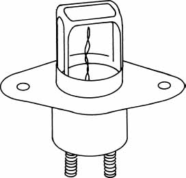
FIGURE 18-3 A thermocouple heat detector.
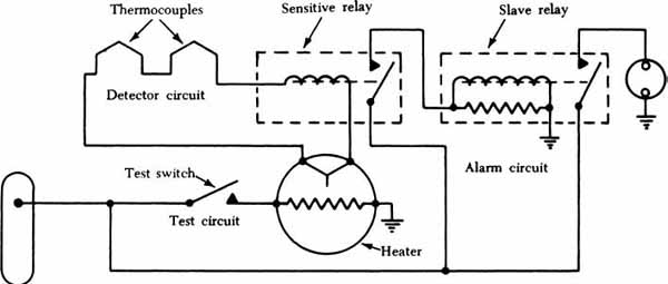
FIGURE 18-4 Thermocouple fire warning circuit.
A test circuit is provided for the system through the use of a heater next to a thermocouple. When the heater is energized, the thermocouple will generate sufficient current to activate the system.
There are three types of tubular sensing devices, called “continuous-loop” systems, commonly employed in modern aircraft for detecting overheat or fire. These tubular sensors are manufactured in lengths from 18 in [0.46 m] to more than 15 ft [4 to 5 m]. The diameters of these sensing elements may be from less than 0.060 in [1.5 mm] to more than 0.090 in [2.3 mm].
Cross-sectional drawings to illustrate the operating principles of the three most commonly employed sensors are shown in Fig. 18-5. These are the sensors manufactured by the Fenwal Company, the Walter Kidde Company, and the Systron-Donner (Meggit safety systems) Company.
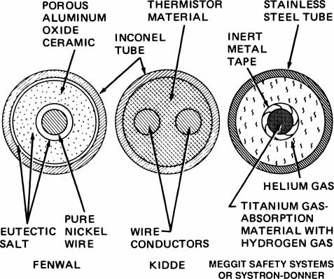
FIGURE 18-5 Drawings to illustrate the operation of overheat and fire sensors.
The Fenwal sensor consists of a small [0.089-in OD (2.3-mm)], lightweight, flexible Inconel tube with a pure nickel wire–center conductor. The space between the nickel conductor and the tubing wall is filled with a porous aluminum-oxide, ceramic insulating material. The voids and clearances between the tubing and the ceramic material are saturated with a eutectic salt mixture, which has a low melting point.
The nickel wire in the center of the tube is insulated from the tube wall by the ceramic and eutectic salt materials. The tube is hermetically sealed at both ends with insulating material, and threaded fittings are located at each end of the tube.
When heated sufficiently, current can flow between the center wire and the tube wall because the eutectic salt melts, and its resistance drops rapidly when the temperature reaches a given level. The elevated temperature will cause a response at any point along the entire length of the sensing element. The increased current flow between the nickel center wire and the tubing wall provides the signal, which is utilized in the electronic control unit to produce the output signal that actuates the alarm system.
When the fire is extinguished or the overheat condition is corrected, the eutectic salt in the sensing element increases in resistance and the system returns to the standby condition. If the fire should reignite, the sensor would again produce a signal for an alarm.
The sensing element of the Kidde system consists of an Inconel tube filled with a thermistor material. Two electrical conductors are embedded in this material, and one of the conductors is grounded to the outer shell of the connector at the end of the tube. Electrical connectors are provided at both ends of the tube.
In the Kidde sensing element the resistance of the thermistor material decreases rapidly when a high temperature is applied. This change in resistance is sensed by the electronic control circuit monitoring the system, and the control provides the warning signal to illuminate the fire warning light and activate the aural warning device. This sensor returns to a normal (standby) condition when the fire or overheat condition is corrected.
The sensing element assembly utilized in the Kidde fire and overheat warning system consists of a pair of sensing elements mounted on a preshaped, rigid support tube. The sensing elements are held in place by dual clamps riveted to the tube assembly approximately every 6 in [15 cm]. Asbestos grommets are provided to cushion the sensor tubing in the clamps. Four nuts per assembly are used to secure the sensing element end connectors to the bracket assemblies at either end of the support-tube assembly. The nuts are secured with safety wire.
The two sensing elements mounted on the support-tube assembly provide separate sensing circuits, and each is connected to its own electronic control circuit mounted on a separate circuit card. This arrangement provides for complete redundancy, thus ensuring operation of the system even though one side may fail.
A Kidde (left) and Fenwal (right) sensor assembly is shown in Fig. 18-6. These assemblies are preshaped to fit the contours of the area in which they are installed.
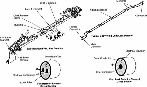
FIGURE 18-6 Fire and duct leak detectors used in typical engine and APU fire detection systems.
A drawing of the control unit for the Kidde system is shown in Fig. 18-7. Signals from the sensing units are processed in the control unit to provide visual and audible warnings in the flight compartment. The control unit is basically a transistorized electronic device consisting of two component board assemblies, a test switch, test jacks, wiring harness, and an electrical receptacle, all enclosed in a metal case.

FIGURE 18-7 Control unit for Kidde system. (Walter Kidde & Co.)
There are two identical circuits in the control unit, one monitoring sensing element loop A and the other monitoring sensing element loop B. Each circuit is contained on its own component board assembly. Remember that in the Kidde system, two sensing elements are mounted on a preformed support-tube assembly. If one circuit should fail, the other circuit will provide the overheat or fire warning signal.
The sensing element produced by Meggit safety systems also known as Lindbergh or Systron-Donner, shown in Fig. 18-8, is pneumatic in operation. The pressure of the gas inside the element is increased by heat, and the increased pressure actuates a diaphragm switch inside the responder, which closes the circuit and provides the warning signal.
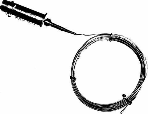
FIGURE 18-8 A Systron-Donner pneumatic fire detection unit. (Systron-Donner Corp.)
The sensing element consists of a stainless steel tube containing two separate gases plus a gas-absorption material in the form of a wire inside the tube. Under normal conditions, the tube is filled with helium gas under pressure. The titanium center wire, which is the gas-absorption material, contains hydrogen gas. The wire is wrapped in a helical fashion with an inert metal tape for stabilization and protection. Gaps between the turns of the tape allow for rapid release of the hydrogen gas from the wire when the temperature reaches the required level.
The sensor responds in accordance with the law of gases. If the volume of gas is held constant, its pressure will increase as temperature increases. The helium gas in the tube exerts a pressure proportional to the average temperature along the entire length of the tube. This is the averaging, or overheat, function of the sensor. If the average temperature exceeds a specified level, the helium gas pressure will be such that it closes the pneumatic switch in the responder and signals an overheat condition. If there is a very high temperature, as a fire would cause, anywhere along the sensing element, the center wire in the tube will release a large quantity of hydrogen gas. This will increase the total gas pressure in the tube to a level that will close the pneumatic switch. This is called the discrete function of the sensor. These operations are shown in Fig. 18-9.
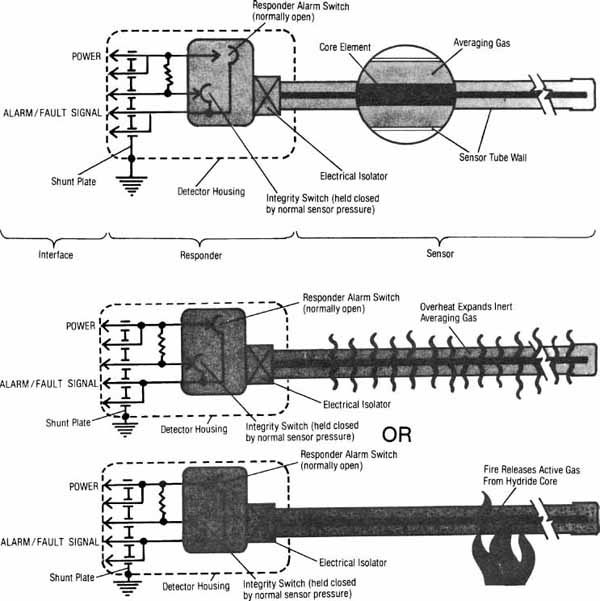
FIGURE 18-9 Operation of the Systron-Donner pneumatic fire detector. (Systron-Donner Corp.)
When a fire is extinguished and the temperature begins to drop, the specially processed titanium wire in the tube will reabsorb the hydrogen gas and reduce the pressure in the tube. This will cause the pneumatic switch to open, and the system will be back to normal and ready to provide another signal in case of reignition.
The responder contains two identical diaphragm switches. One of the switches is normally open and closes only when gas pressure in the sensor tube increases owing to high temperature or fire in the area where the sensor is installed. The other switch is held closed by the normal helium pressure in the sensor tube. If the helium pressure should be lost, the switch opens the test circuit. When the test switch is closed by a member of the crew to check the circuit, the alarm will not respond and the loss of helium will be revealed.
The continuous-loop (Kidde and Fenwal) and continuous-length (Systron-Donner) types of fire detection mechanisms are considered superior to the spot and thermocouple systems where large areas must be covered, such as around a jet engine. The continuous-loop systems do have a disadvantage in that damage to the tubing wall, which will cause it to be closer to the center elements, may cause false fire signals to be generated.
The continuous-length sensor is not as sensitive to damage as are the continuous-loop sensors. The outer tubing of these units can be bent, dented, kinked, and otherwise distorted without their effectiveness being affected. The wire inside the tube prevents complete collapse, so there is always room for gas to flow. The only cause of failure is loss to the helium gas because the tube is worn or cut sufficiently to allow the gas to escape.
Each of the different sensor mechanisms can be selected for various operating temperatures. For example, the normal temperatures surrounding the turbine-engine combustion chamber will be much higher than the normal temperatures in the area of the engine inlet. A sensor selected for the inlet area of the engine should actuate the alarm system at a lower temperature than the sensor used near the engine combustion chamber. Different temperature-rating detectors may be included in a common alarm system such as the one shown in Fig. 18-10. The section from point 1 to point 2 uses a detector that will activate the alarm at 425°F [218°C], the area from 2 to 3 will activate the system at about 640°F [338°C], and the section between 3 and 4 will indicate a fire or overheat when the temperature exceeds 450°F [232°C]. For this reason, when installing or inspecting sensor units, always be sure that the proper heat rating is being used.
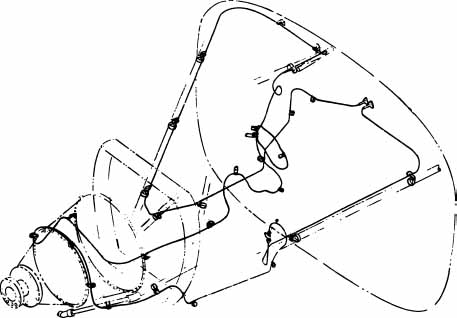
FIGURE 18-10 The routing of a continuous-loop fire detection assembly in an engine compartment. (Cessna Aircraft Co.)
Installation and Routing of Sensing Units
The installation of overheat and fire warning sensing units must be done strictly in accordance with the instructions provided by the manufacturer. The routing of the sensors has been designed by engineers to provide the most effective performance and the detection of overheat or fire in the most likely areas. Routing must also take into consideration possible damage to the sensors. For example, in a baggage or cargo compartment, the sensors must be placed where there is no chance that cargo or luggage will strike them and cause damage.
Sensors must be supported with specially designed clamps in which the small tubing is held in rubber or soft plastic grommets. These prevent damage due to vibration and wear. The clamps with grommets must be spaced as specified in the appropriate instructions.
A typical method for installing the sensing element in an airplane is shown in Fig. 18-11. Electrical connector fittings are employed to connect the sensor into the circuit. The tubing of the sensor is held in place by means of mounting clips. The grommet placed around the tubing in the clip is essential to prevent damage due to chafing and vibration. The sensing element must be routed as described in the aircraft maintenance manual. A Systron-Donner system would be mounted in a similar manner except that connections are only made at the responder.
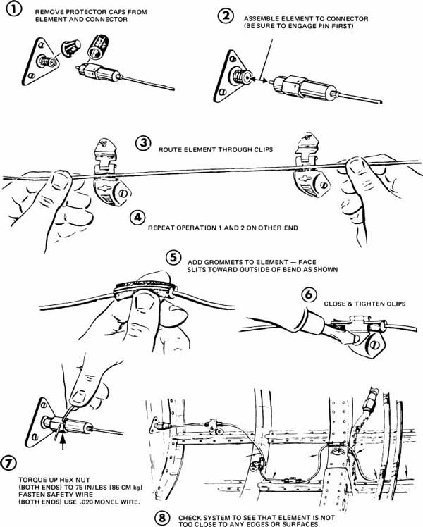
FIGURE 18-11 Installation procedure for a tubular sensing unit. (Fenwal, Inc.)
Typical installations for continuous systems are shown in Figs. 18-12 and 18-13.
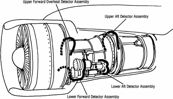
FIGURE 18-12 Pneumatic sensor locations around a jet engine. (Systron-Donner Corp.)
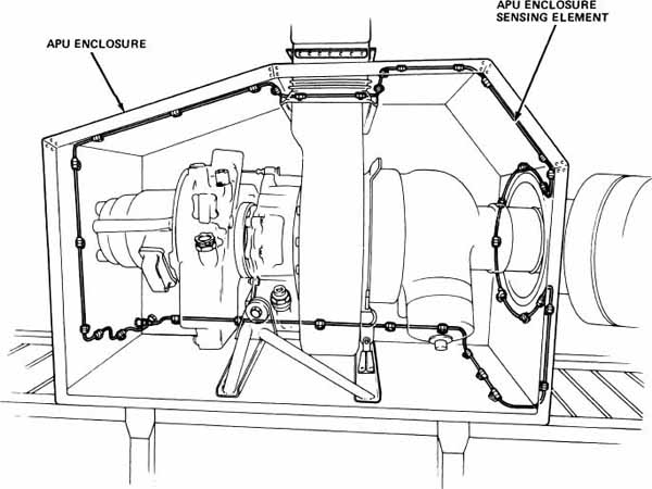
FIGURE 18-13 Continuous-loop sensor in an auxiliary power unit (APU) compartment. (Canadair Inc.)
Smoke- and Toxic-Gas-Detection Systems
Smoke-detection systems are usually installed to monitor the condition of the air in cargo and baggage compartments, where considerable smoke may be generated before the heat level reaches the point at which it sets off the overheat and fire warning system. Detectors (sensors) are placed in locations at which they are most likely to provide the earliest possible warning.
Toxic-gas (carbon monoxide) detectors are usually installed in cockpits and cabins, where the presence of the gas would affect the flight crew and passengers. Carbon monoxide (CO) is a clear gas and is not detectable by the type of smoke detectors that rely on a change in the transmission of light through a sample of air.
Smoke and flame detectors operate according to several different principles. Among these are light detection, light refraction, ionization, and the change in resistance of a solid-state semiconductor material.
In a light-detection system, a photoelectric cell such as the one in Fig. 18-14 is placed in a location where it can “see” the surrounding area and produce a change of current flow when there is a change in the visible light or infrared radiation striking the cell. (Units are designed to detect either visible light or infrared radiation.) This change in current flow is used to activate an amplifier circuit, which produces the visual and aural alarm signals. This type of system is activated only by an open flame.

FIGURE 18-14 A flame detector. (Pyrotector.)
In a light-refraction detector, shown in Fig. 18-15, a light beam is passed through the detection chamber, and a photoelectric cell is placed in the chamber, where it is shielded from the direct light of the light source. Air from the area being monitored for smoke and fire is passed through the detector unit by normal airflow or by means of a fan or other device. When smoke is introduced into the chamber, the light from the particles of smoke is reflected into the photoelectric cell. This changes the resistance (conductivity) of the photoelectric cell and changes the flow of current through the cell. This change in the flow of current activates the amplifier and produces the visual and aural warning signals. A schematic drawing of the chamber is shown in Fig. 18-16 and a typical system wiring diagram is shown in Fig. 18-17.
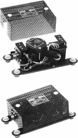
FIGURE 18-15 A smoke detector. (Pyrotector.)
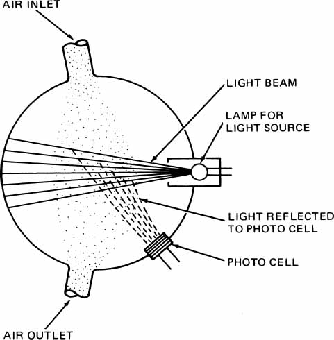
FIGURE 18-16 Detector utilizing light refraction with a photoelectric cell.
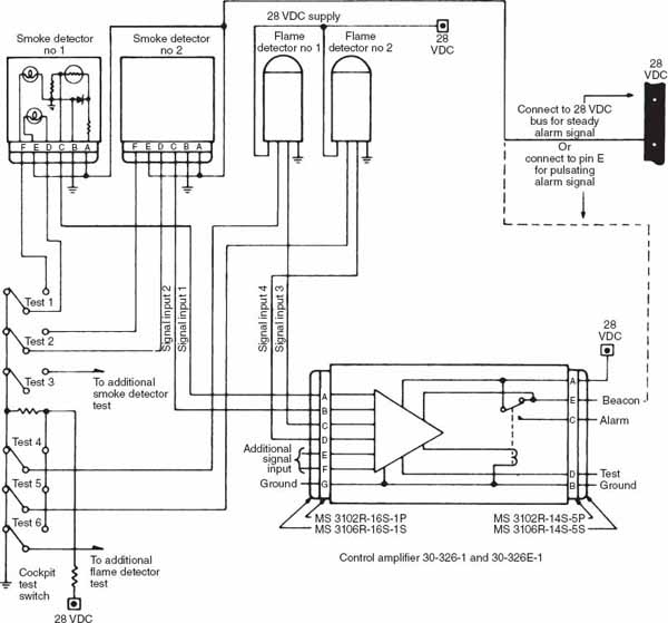
FIGURE 18-17 Typical wiring diagram for a smoke and flame fire detector system. (Pyrotector.)
In an ionization-type smoke detector, a small amount of radioactive material is used to bombard the oxygen and nitrogen molecules in the air within the detection chamber. The ionization that takes place permits a small current to flow through the chamber and in the external circuit. Air from the area being checked for smoke is passed through the chamber, as shown in Fig. 18-18. If smoke is in the air, small particles of the smoke attach themselves to the oxygen and nitrogen ions and reduce the flow of current. When the current level is reduced by a predetermined amount, the alarm circuit will be triggered to produce the visual and aural alarm.

FIGURE 18-18 An ionization-type detector cell.
The solid-state type of smoke or toxic-gas detection utilizes two heated, solid-state detecting elements. Each element is approximately 1 mm [0.0394 in] in diameter and consists of a heating coil encased in a coating (substrate) of the solid-state (semiconductor) material. The composition of the sensors is such that ions of carbon monoxide or nitrous oxide will be absorbed into the solid-state coating of the sensing element and change its current-carrying ability.
The system operates by comparing the electrical output of the two sensors, one of which is exposed to outside air and the other to cabin air. The sensors are connected in separate legs of a modified bridge circuit. When both are conducting equally, there will be no output and no signal. If the sensor sampling cabin air absorbs toxic gases from the cabin air inlet, the bridge circuit will be unbalanced, and this will produce the current flow that activates the warning system. The warning is provided by an illuminated annunciator unit. An aural signal can also be produced.
A circuit to illustrate how electrical-type sensors are connected to develop a warning signal is shown in Fig. 18-19. The bridge part of the circuit is designed to be in balance when the two sensing elements are conducting the same current. If one of the sensors changes its resistance or conductivity because of exposure to light or smoke, the bridge is unbalanced, and a small current flow will occur through the sensitive relay. When this current reaches the predetermined alarm level, the relay will close and send current to the main signal relay. This relay closes the circuit to the alarm elements (light and aural warning unit) to provide the warning.
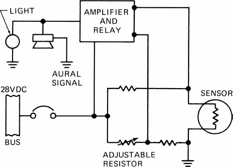
FIGURE 18-19 Circuit to illustrate the use of a resistance bridge to compare sensor resistance with that of a reference resistor.
Fire-Extinguishing Agents
Fire-extinguishing agents are those chemicals that are injected into a compartment or area to extinguish a fire. These agents work by either displacing the oxygen or chemically combining with the oxygen to prevent combustion. Some additional extinguishing effect can occur by the low temperature at which the agents are discharged.
The commonly used agents are carbon dioxide (CO2), Freon (a chlorinated hydrocarbon), and Halon 1301 (mono-bromotrifluoromethane—CF3Br). Nitrogen (N2) is also an extinguishing agent but is used primarily in current systems as a propellant for one of the other chemicals. Freon and Halon are in a liquid state when under sufficient pressure but become gaseous when released to atmospheric pressure. Liquid Freon and Halon must not be allowed to come into contact with the skin because they will cause frostbite due to the extremely low temperatures attained when the liquid evaporates.
Most modern aircraft extinguishing systems make use of Halon 1301 as the extinguishing agent, whereas some manufacturers specify Freon. The use of CO2 is usually limited to older, reciprocating-engine-powered transports.
Dry-chemical extinguishing agents are not used for aircraft fire-extinguishing systems, and their use for hand-held extinguishers has decreased greatly. Dry chemical agents are toxic and corrosive, whereas other agents, being gaseous, do not cause corrosive action to occur. Some of the gaseous agents may be considered toxic while they are present in an area in large quantities because of the displacement of free oxygen.
While Halon 1301 is still in service, the production of this ozone-depleting agent has been restricted. Although not required, consider replacing Halon 1301 extinguishers with Halon replacement extinguishers when discharged. Halon replacement agents found to be compliant to date include the halocarbons HCFC Blend B, HFC-227ea, and HFC-236fa.
Fire-Suppression Systems
Fire-suppression or fire-extinguishing systems usually consist of a fire-extinguishing agent stored in pressurized containers, tubing to carry the extinguishing agent to areas that require protection, control valves, indicators, control circuitry, and associated components. Systems vary considerably on different aircraft; however, the basic elements are similar.
Extinguishing-agent containers for modern aircraft are usually spherical or cylindrical in shape. Typical containers are shown in Fig. 18-20. The containers shown are pressure tested hydrostatically at 1500 psi [10 342 kPa]. When charged, the spherical container holds 60 lb [27.22 kg] of Halon, and the cylindrical container holds 105 lb [47.63 kg] of Halon. An additional 300-psi [2068-kPa] nitrogen charge is placed in the containers to expel the agent. A discharge head containing an explosive cartridge is installed on one or both of the container necks to discharge the container by rupturing the disk when the cartridge is activated. One type of cartridge is shown in Fig. 18-21. The squib is the explosive charge that drives the slug through the disk. A screen in the discharge head prevents particles of the disk from entering the deployment lines.

FIGURE 18-20 Typical extinguishing-agent containers. (Walter Kidde & Co.)
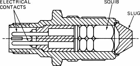
FIGURE 18-21 Explosive cartridge. (Walter Kidde & Co.)
A thermal pressure relief fitting is located on each bottle. If the bottle pressure exceeds approximately 1400 psi [9653 kPa], the fitting will discharge the bottle contents either overboard or into the compartment containing the bottles.
Older aircraft still using CO2 as the extinguishing agent use one or more gas cylinders equipped with quick-acting flood valves. When activated, the flood valves rapidly discharge the bottles into the distribution lines. The bottles have a thermal relief mechanism that automatically discharge the bottles when the internal pressure exceeds 2650 psi [18271.75 kPa].
Two methods are used to allow the pilot or technician to determine if the bottle has discharged thermally: a pressure gauge or a “blowout” disk. Some aircraft have a gauge for the fire bottles visible from the outside of the aircraft or through access panels. If the gauge does not indicate a charge, then the bottle has been discharged. Other aircraft have a discharge line running from the bottle to the outside of the aircraft or to an open area such as a wheel well. The discharge line opening is covered with a red disk. If the bottle has discharged, the disk will be blown out of the discharge fitting. The absence of the red disk indicates a thermal discharge.
A similar system is used to indicate if the system has been discharged by actuation of the extinguishing system. In this case a small line from the system distribution line leads to a disk-actuator line. This line is covered with a yellow disk. When the extinguishing system is activated, the yellow disk is pushed out by a plunger.
There are two classifications of fire-extinguishing systems, the conventional system and the high-rate-of-discharge system (HRD system).
The conventional system is normally found on older reciprocating-engine-powered aircraft and is based on the design concept of the systems first used on aircraft. Although this type of system is adequate, it is not as efficient as the HRD systems. The conventional system usually uses CO2 as the extinguishing agent and makes use of a perforated ring and distributor-nozzle discharge arrangement. When the system is activated, the CO2 bottles are opened and the gas flows through the lines to the selected engine. At the engine the gas flows out of the perforated ring and distributor nozzles to smother the fire.
The HRD system uses Freon or Halon 1301 and the spherical bottles actuated by explosive cartridges. The discharge tubes are configured to allow a rapid release of agent into the fire area and flood the compartment to eliminate the fire quickly. The advantage of this system over the conventional system lies in the ability to flood a compartment much more quickly.
Both conventional and HRD systems may be designed to allow only one extinguishing agent to discharge into a fire area, or they may be designed to allow several discharges into an area in an attempt to extinguish the fire. In most aircraft only two discharges are possible for any one location. The exact configuration of a system is determined by the aircraft manufacturer.
A schematic diagram of a typical fire-suppression system for an airliner is shown in Fig. 18-22. The system consists of two steel containers charged with Freon and nitrogen gas to a pressure of 600 psi [4136 kPa], connecting deployment lines to the control valves and control circuitry. The system is activated when a member of the crew closes the fire switch to direct extinguishing agent to the area where a fire is indicated.

FIGURE 18-22 Schematic diagram of a fire-suppression system. (Boeing Co.)
When the fire-extinguishing switch is closed, an explosive charge at the neck of the selected agent container is detonated and a cutter is driven through the sealing disk in the neck of the container. This instantly releases the extinguishing agent from the container and permits it to flow to the area selected. The pilot or other crew member will have selected the appropriate area by operating a switch on the fire control panel. This will direct the agent through the correct deployment line.
Figure 18-23 shows the extinguisher system used on a modern turboprop aircraft. Each engine system is independent, and only one discharge is available to extinguish the fire.

FIGURE 18-23 Fire-extinguishing system configuration for a twin-engine turboprop airplane. (Flight Safety International.)
Figure 18-24 shows the system for a twin-engine helicopter. One or both bottles can be used to extinguish a fire in either engine area. By moving the engine toggle switch from NORM to ARM, fuel is shut off to the engine and the system is armed. When the springloaded-to-center toggle marked AGENT RLSE is moved to the right or the left, the appropriate bottle will discharge into the armed engine area.
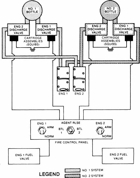
FIGURE 18-24 Fire-extinguishing system schematic for a twin-engine helicopter. (Flight Safety International.)
Portable Fire Extinguishers
Portable or hand-held fire extinguishers must be available as specified for the aircraft. The fire extinguishers must be of approved types and must be appropriate for the kinds of fires that are likely to occur in the areas concerned. For example, if electrical fires are most likely, the fire extinguisher must be of the dry-chemical type, a dry-gas type (CO2), or a Halon 1301 type. Extinguishing agents containing water must not be used, because water increases electrical conductivity and may cause more damage than good. Oil or fuel fires should be smothered with a foam-type agent or a dry-chemical agent.
Each extinguisher for use in a personnel compartment must be designed to minimize the hazard of toxic gas concentrations. Readily accessible hand-held fire extinguishers must be available for use in each Class A or Class B cargo compartment. Class A and Class B cargo compartments are those accessible to members of the flight crew while the aircraft is in flight.
Inspection and Servicing of Fire Protection Systems
Inspections for fire warning and fire-suppression systems follow the general procedures for the inspections of other systems. Mechanical parts of systems are examined for damage, wear, security of mounting, and compliance with technical and regulatory requirements. Electrical control systems are inspected in accordance with approved practices for electrical systems and the special instructions given in the manufacturer’s instructions. Certain elements must be electrically tested with voltmeters, ohmmeters, meggers, or otherwise, as specified in the maintenance instructions. Continuity of electrical circuits may be tested with ohmmeters or continuity test lights.
For additional information on the maintenance and service of fire protection systems, refer to the text Aircraft Powerplants.
For service of particular fire warning and fire-suppression systems, the technician must follow carefully the appropriate manufacturer’s instructions. This is to ensure that the correct materials are employed and the proper procedures are followed.
ICE PROTECTION SYSTEMS
All aircraft that operate in weather conditions where ice is likely to form must be provided with ice protection. This protection may be in the form of anti-icing systems or deicing systems. An anti-icing system prevents the formation of ice on the airplane, and a deicing system removes ice that has already formed.
Among the parts of the airplane where ice prevention or removal is essential are the windshield, wing leading edges, tail airfoil leading edges, propellers, engine air inlets, pitot tubes, water drains, and any other part where the formation of ice can interfere with the operation of the airplane or its systems.
On piston-engine airplanes, especially those equipped with float-type carburetors, carburetor anti-icing is necessary, even in clear weather, when the temperature and humidity are conductive to the formation of ice in the throat of the carburetor.
Ice Detection Systems
Some method of ice detection is desirable for aircraft so that the ice-control systems are operated only when necessary. If ice-control systems were operated continuously, there would be a significant increase in operational expense due to increased wear and tear on equipment and the consumption of fluids and power unnecessarily. There are two basic methods used for ice detection: visual and electronic.
Visual detection is achieved by the flight crew monitoring the aircraft structures that first start to accumulate ice on their particular aircraft. This may involve no more than looking at the wing leading edge or checking the windshield wiper for ice buildup. At night this visual checking is aided by the use of lights designed to shine on the surface that accumulate ice. Many aircraft have ice lights mounted on the side of the fuselage or the side of the engine nacelle. These lights are usually aimed to shine on the wing surface.
Electronic instruments can be used to detect ice accumulation when there is no surface easily seen by the flight crew. One such system is used on the Canadair Challenger 601 and is shown in Fig. 18-25. The ice detector consists of a microprocessor circuit with an aerodynamic strut and probe extending into the slipstream. The probe vibrates at a frequency of 40 kHz. When ice starts to build on the probe, the frequency will decrease. When the frequency has decreased to a preset value, the microprocessor will turn on a red annunciator light to advise the flight crew that the aircraft is in icing conditions. If the flight crew then turns on the ice-control systems, the red ICE light will go out and a white ICE light will illuminate. Once the probe detects ice, the microprocessor will energize a heating element in the probe to remove all ice so that the probe can recheck for icing conditions. As long as the probe continues to detect icing at each check, the ICE annunciator will remain on. When ice is no longer detected, the light will go out. The 601 has two of these detectors, one on each side of the forward fuselage section.

FIGURE 18-25 An electronic ice detector. (Canadair Inc.)
Pneumatic-Mechanical Deicing Systems
For many years, various airplanes have utilized mechanical deicing systems consisting of inflatable rubber “boots” formed to the leading edge of wings, struts, and stabilizers. The deicing boots are attached to the leading edge of the airfoils by means of cement and fasteners such as rivnuts, also called “bootnuts.” Rivnuts are described in the section of this text covering structural repairs. Some aircraft use cement only for attaching the deicer boots to leading-edge surfaces.
The inflatable boots are usually constructed with several separate air passages or chambers, so that some can be inflated while alternate chambers are deflated. The inflation of the boot is accomplished by utilizing the output pressure from a vacuum pump for inflation and the inlet side of the pump for deflation. The control of the pressure and suction is accomplished by means of a distributor valve, which rotates and periodically changes the flow of air to or from the different section of the boots, or by flow-control valves. This results in alternate raising and lowering of sections of the boots, and this action cracks off any ice that has formed on the boots.
The pneumatic deicing system installed on one model of a twin-engine airplane provides a good example of the application of such a system. The system as installed in the airplane is illustrated in Fig. 18-26.

FIGURE 18-26 Pneumatic-mechanical deicing system on a twin-engine airplane. (Piper Aircraft Co.)
Deicer boots, also referred to as deicers, consist of fabric-reinforced rubber sheets containing built-in inflation tubes. The operation and design of these deicer boots are shown in Fig. 18-27. The boots used in this installation have spanwise inflation tubes. The deicers are attached by cement to the leading edges of the surfaces being protected. Either aluminum or flexible rubber air connections called air-connection stems are provided on the back side of each deicer. Each stem projects from the underside of the boot into the leading edge through a round hole provided in the metal skin. These provide for connection to the deicer pneumatic system.
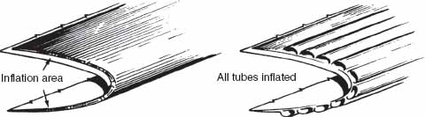
FIGURE 18-27 Construction and operation of deicer boots. (Piper Aircraft Co.)
Through the engine-driven vacuum pumps, the system normally applies vacuum to the deicer boots at all times except when the boots are being inflated. When it is desired to inflate the deicer boots, the pilot or copilot uses the deicer system control switch. This is a momentary ON–type switch that returns to OFF when released. When the control switch is turned ON, the time module (timer) energizes the pneumatic pressure control valve for 6 s. The boot solenoid valves are energized, and air pressure from the engine-driven pumps is supplied to the inflatable tubes in the boots. The inflation sequence is controlled by the time module (timer) and solenoid-operated valves located near the deicer air inlets. Upon automatic de-energization of the control valves by the timer, the deicer solenoid valves permit the deicer pressurizing air to return to the solenoid valves and be exhausted overboard. Deicer pressure is normally about 18 psig [124 kPa]. After the boots have been inflated and the pressure released as described, vacuum is again applied to the boots.
The wing and horizontal stabilizer pneumatic deicing system for a small jet is discussed. Figure 18-28 shows the central part of the system that provides dried air and proper pressure for the wing and horizontal stabilizer deicing system.
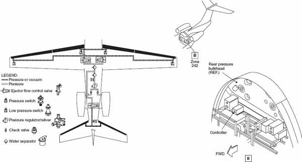
FIGURE 18-28 Deice system of small jet aircraft.
This is accomplished by the water separator and pressure regulator/reliever. Two check valves avoid backflow when there is loss of bleed air from one engine. The low-pressure switch monitors the system pressure and indicates when inadequate (low) pressure is provided to the wing and horizontal stabilizer deicing system. The controller monitors the deice pressure switches and the low-pressure switch and indicates a fault to the flight crew in case of under-pressure, inflation, or deflation problems.
Deicer Check Valve
The deicer check valve (CV) is a spring-loaded flapper valve that, with its metal sealing surfaces, is designed to withstand high-bleed air temperatures while providing a positive seal against engine bleed air backflow with minimum leakage. The valve is also designed for minimum pressure drop and flow resistance in the forward flow condition. Check valves are used on duel-engine aircraft in which pressurized bleed air from both engines is supplied to a pneumatic deicing system through a common manifold. The check valves provide positive seal against engine bleed air backflow in the event of loss of bleed air from one engine. This ensures that the pressure to the deicing system is maintained in the event bleed air is only available from one engine.
Pressure Regulator/Reliever
The pressure regulator/reliever is designed to receive inlet air pressure from an engine bleed air source and to provide a constant outlet pressure for deicer inflation, over a wide range of flow rates and inlet pressures. Outlet pressure regulation is accomplished by means of a variable orifice which opens and closes to modulate the flow area. The orifice is formed by a poppet which moves relative to a fixed seat located in the regulator housing. The poppet is attached to a spring-loaded diaphragm which senses outlet pressure and closes the poppet in the event of high outlet pressure, and opens the poppet in the event of low outlet pressure. The regulator is equipped with an over-pressure relief valve, or reliever, which serves as a fail-safe device for venting excess pressure overboard in the event the regulating poppet fails in the open position. The reliever consists of a self-resetting spring-loaded ball, which opens at a preset pressure. The reliever is installed to one of the two outlet ports of the regulator housing.
Water Separator
The water separator serves to eliminate the majority of liquid water from the air line by means of centrifugal separation in order to minimize the potential of valve freeze-up. The separator has a continuous drain port, which should be located downward (toward gravity). The separator drain port is equipped with a fitting to allow drain water to be routed to another location if desired. Its inlet pressure rating is 100 psig (maximum).
Low Pressure Switch
The switch is located upstream of the ejector flow control valves (EFCVs) and is used to monitor the system pressure to ensure a minimum pressure is being supplied to the EFCVs.
Controller
The controller provides the command signals to the EFCVs. The controller operates in a 1-min mode using the control switch. A single cycle mode can be initiated by momentarily toggling the control switch from the OFF position to the ON position and then back to OFF. This provides the pilot with immediate operation of the boot deicing system. Power input to the controller consists of 28-V dc. The controller will communicate status and fault messages to the data concentrator unit via ARINC 429. The fault messages will indicate a pressure fault or a stepping fault. A timed pressure fault is one or a combination of the following:
• Failure of a pressure switch to close within 4 s of activation of its associated ejector flow control valve, indicating failure of the deicer to inflate to operating pressure in proper time.
• Failure of a pressure switch to reopen within 4 s of deactivation of its associated ejector flow control valve, indicating failure of the deicer boot to deflate in the proper time.
• A deice pressure switch is not open when the controller is not cycling.
• The low-pressure switch is not open within 4 s after a valve is actuated.
Wing Deice System
The wing deicing system removes the formation of ice from the wing leading edges. Figure 18-29 shows the components of the wing deice system of a small jet aircraft.
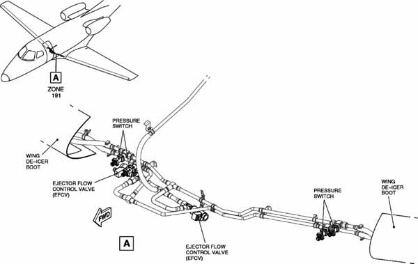
FIGURE 18-29 Wing deice system components of small jet aircraft.
The wing deicer boots cycle (inflate/deflate) in order to mechanically remove the formation of ice from the wing leading edges. The EFCV provides the boot inflation and deflation. Pressure switches monitor the boots pressure to ensure that they work properly.
Wing Ejector Flow Control Valve
The aircraft has three EFCVs. There are two EFCVs for the wing deicing system and one for the horizontal stabilizer deicing system. The EFCV controls the flow of air to and from the deicer boots. It is a two-position, solenoid-operated poppet valve that provides system pressure (energized position) or vacuum to the pneumatic deicers. When the solenoid valve is in the de-energized condition, the ejector section of the valve provides the vacuum necessary to maintain the deicing tubes in a deflated condition using a minimum amount of airflow. The vacuum generated is 5.0 at the inlet of 18 psig and 21°C [70°F].
Wing Deice Pressure Switch
The aircraft has five deice pressure switches. Four pressure switches for the wing deicing system and one pressure switch is dedicated to the horizontal stabilizer deicing system. The wing deice pressure switches are located at the inlets of both the inboard and outboard LH (Left-Hand) and RH (Right-Hand) chambers of the wing deicer boots and downstream of the EFCVs. The pressure switches ensure a minimum pressure is being supplied to the deicers in a specific timing window.
Wing Boot Deicer
The wing deicer boots are silver polyurethane-surfaced pneumatic deicers consisting of a smooth rubber and fabric blanket containing span-wise deicing tubes. Each wing deicer boot is a single boot with separate inflatable chambers, one for the inboard wing section and one for the outboard wing section. Each wing deicer boot has an inboard and an outboard air connection for inflation. The LH and RH outboard chambers of the deicer boot will inflate simultaneously. The LH and RH inboard deicers will inflate simultaneously. The inflation pressure of the deicer boot is 20.0 ± 1.0 psig.
Horizontal Stabilizer Deicing System
The horizontal stabilizer deicing system removes the formation of ice from the horizontal stabilizer leading edges, as shown in Fig. 18-30.
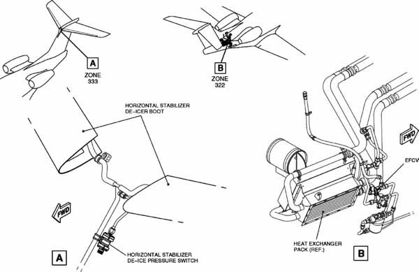
FIGURE 18-30 Horizontal stabilizer deicing system components.
The horizontal stabilizer deicer boots cycle (inflate/deflate) in order to mechanically remove the formation of ice from the horizontal stabilizer leading edges. The EFCV provides the boot inflation and deflation. A pressure switch monitors the boot pressure to make sure that the system works properly. The components of the horizontal stabilizer deicing system are similar to the components of the wing deicing system.
Inspection and Maintenance of Pneumatic-Mechanical Deicer Systems
The inspection of pneumatic-mechanical deicer systems requires an examination of the deicer boots for condition, adherence to the protected surface, and condition of the surface of the boots. If cuts, abrasion, or other damage is found, repairs should be made as specified by the manufacturer. Grease or oil found on the boots should be removed with an approved solvent, after which the boots should be scrubbed with soap and water and then rinsed with clean water.
Deicer boots are provided with a conductive neoprene coating to prevent the buildup of static charges on the boots. If this were not done, static charges would build up and then discharge to the metal surface of the airplane, causing radio interference. During inspection and maintenance, the technician should determine whether the conductive coating is intact and effective.
Removal and replacement of deicer boots depends upon the type of attachment involved. If the boots are attached with screws and rivnuts, removal of the screws permits removal of the boots. If the boots are cemented, the technician must consult the manufacturer’s instructions regarding the type of solvent to be used for dissolving the cement and the procedure for applying the solvent.
Operational tests are performed as specified in appropriate instructions. Usually, the test can be made by running one or more engines and turning the system on in the normal manner. The inflation of the tubes in the boots can easily be observed. If any of the tubes should fail to inflate in sequence or at the proper time, the air supply to that tube should be checked for obstruction or damage.
Thermal Anti-Icing
Thermal anti-icing uses heated air flowing through passages in the leading edge of wings, stabilizers, and engine cowlings to prevent the formation of ice. The heat source for this operation normally comes from combustion heaters in reciprocating-engine-powered aircraft and from engine bleed air in turbine-powered aircraft. From the heat source the hot air is distributed along the leading edge of the item being anti-iced by the use of a perforated air duct called a piccolo, or spray, tube. When the air exits the piccolo tube, it is in contact with the leading-edge skin of the surface, as shown in Fig. 18-31. The skin is heated and ice is prevented from forming. The air then flows out of the wing through openings in the end of the wing or on the bottom of the wing.

FIGURE 18-31 A typical heated leading edge.
Figure 18-32 is a drawing of the layout of the Boeing 777 anti-ice system. The anti-ice system consists of ice detection, windshield rain removal, window heat, air data probe heat, engine anti-ice, wing anti-ice, and water and waste heat. Figure 18-33 shows the wing anti-ice schematic of a Bombardier 700 aircraft. The wing anti-ice system prevents ice formation on the wing-leading edge by heating the surface using hot engine bleed air. The hot bleed air is supplied through insulated ducting and released through piccolo tubes to the inner surface of the wing and slat-leading edges. Air is then extracted overboard between the slat and the main wing. The wing anti-ice system is divided into identical left and right systems. In normal operation, each engine supplies bleed air to its respective wing anti-ice system. The systems are connected by a normally closed, wing anti-ice cross bleed valve. In the event one system fails, the cross bleed valve is opened to permit cross bleed between systems. This ensures that wing anti-icing is maintained to both systems. The system is manually activated and is automatically controlled by a dual channel digital anti-ice and leak detection controller (AILC). The AILC controls the wing anti-ice system using electrical inputs received from skin temperature sensors located at each wing-leading edge. The AILC modulates the respective wing anti-ice valve open or closed as necessary to prevent ice formation. Each of the two channels of the AILC has the capability to control both left and right anti-ice valves. Figure 18-34 shows the engine indication and crew-alerting system (EICAS) anti-ice page.

FIGURE 18-32 Anti-ice system.

FIGURE 18-33 Wing anti-ice system.

FIGURE 18-34 EICAS anti-ice page indicating overheat situation.
Electro-Thermal Ice Protection
The Boeing 787 utilizes an electro-thermal ice protection system in which several heating blankets are bonded to the interior of the protected slat-leading edges. The heating blankets may then be energized simultaneously for anti-icing protection or sequentially for deicing protection to heat the wing-leading edge. Electro-thermal ice protection is also used on several aircraft to provide anti-icing protection for the horizontal stabilizers.
Probe Anti-Icing
Aircraft are equipped with several sensors and devices that are exposed to the slipstream. These devices are required for safe operation of the aircraft and must be kept free of ice. Starting with the smaller aircraft, the items that need protection from ice buildup include the pitot mast and the stall warning indicator. Larger aircraft require that additional items such as static ports be kept clear, along with total-air-temperature probes and angle-of-attack indicators.
These probes are normally kept free of ice by the use of electric heaters. These heaters are controlled by switches at the pilot’s station. The heater elements may be operated by either ac or dc electrical power.
When inspecting these devices, the technician should be aware that even the units on small aircraft are capable of generating sufficient heat to cause painful burns to the skin. Never touch one of these devices if its heater element is operating. Figure 18-35 shows the electrical heating system for the air data probes on a Boeing 777 aircraft.

FIGURE 18-35 Air data probe heat system.
Windshield-Ice Control
The control of ice buildup on windshields may be accomplished by one of two basic methods: by heating the windshield or by spraying a fluid on the windshield to remove ice and prevent the formation of any more ice. The heating of windshields is the more common method and may involve the use of a heated panel over the windshield surface, electric heater elements inside the windshield structure, or a flow of heated air between windshield surfaces.
Light aircraft can make use of an electrically heated panel to clear ice from the portion of the windshield immediately in front of the pilot. The panel provides a clear area of approximately 12 in [30.5 cm] high by 6 in [15.2 cm] wide, with the size of different units providing different clear areas. This system can be used on aircraft that are not available with internal windshield heater elements, such as most aircraft with plastic windshields.
The system must be placed into operation by the pilot prior to any large ice buildup, because the unit is designed for anti-icing rather than deicing. Once in operation the panel will maintain a surface temperature of approximately 100°F [37.8°C], with the temperature being regulated by a temperature-sensing circuit that cycles the heater elements on and off to maintain the designed operating temperature range.
The panel is mounted on a fixture in front of the windshield and can be removed when the aircraft is not going to be operated in icing conditions. The panel used on the Cessna Caravan is shown in Fig. 18-36. This unit includes a restraining strap (not shown), which prevents the panel from pivoting forward on its mount when reverse thrust is used during landing.
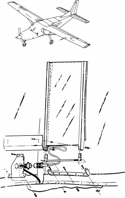
FIGURE 18-36 Heated panel mounted in front of a windshield. (Cessna Aircraft Co.)
Aircraft with integral windshield heaters are normally equipped with glass or hardened acrylic outer layers reinforced internally with shatter-resistant materials such as acrylic and polycarbonate materials and a polyvinyl butyral interlayer, as shown in Fig. 18-37. A conductive coating is placed beneath the glass layer in the area of the windshield to be anti-iced, such as the area shown in Fig. 18-38. When in operation, current flows through the coating and generates heat due to the resistance of the coating. A portion of the windshield or complete panels can be kept ice-free by this method. This method of windshield-ice control is commonly used on turbine-powered corporate and airline-type aircraft.

FIGURE 18-37 Cross section of a heated windshield. (Bell Helicopter Textron.)
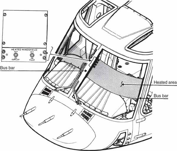
FIGURE 18-38 A heated windshield installation. (Bell Helicopter Textron.)
Some older transport aircraft have windshields that consist of an inner and outer panel separated by an air passage. When windshield anti-icing is turned on, heated air from the cabin heating system is ducted through this passage, heating both panels of glass. The heated air exits the windshield area and flows into the flight deck area.
The following items are important when inspecting heated windshields:
• Check for any delamination (separation of the layers) in the windshield panels.
• Look for any scratching of the windshield and determine its cause. Scratching is often caused by dirty windshield wipers moving across the panel. For this reason, always keep windshield wipers clean and in good condition.
• Any arcing that occurs during operating indicates that the conductive coating may be breaking down. This situation can lead to overheating of the panel where the arcing is occurring. Correct the problem immediately in accordance with the manufacturer’s maintenance instructions.
• Discoloration of the windshield is not normally a problem unless the optical quality of the windshield is affected. Heated windshields are clear when looking directly through them, but they may have a gold, blue, or pink tint to them when viewed with light reflecting off them.
When evaluating any of these types of damage to a windshield, follow the recommendations of the aircraft manufacturer. The basic guidelines are that the damage should not decrease the strength of the windshield, change the optical quality of the windshield, or affect the normal operation of the system.
Alcohol is used on some aircraft to provide for windshield deicing. This system sprays isopropyl alcohol on the outside of the windshield. The alcohol can be used to remove ice, but the supply is not normally great enough to be used throughout the flight. This system is normally used to clear the windshield prior to landing. Operation of the system requires that a crew member turn on the fluid pump and adjust the rate of flow according to the amount of ice that has accumulated. Care should be taken when inspecting this system to ensure that all lines and fittings are in good condition. In-flight fires have resulted from the alcohol line rupturing and spraying onto electrical equipment.
RAIN-REMOVAL SYSTEMS
Rain-removal systems are designed to allow the pilot to have a clear view of the airport when taxiing and to allow him or her to see the approach and departure paths and runway environment when taking off and landing during rain. The systems are not commonly used during flight at altitude.
Rain may be removed by the use of windshield wipers, chemical repellents in combination with windshield wipers, or by a flow of air.
Windshield-Wiper Systems
Windshield-wiper systems may be operated electrically, hydraulically, or pneumatically.
A typical electrically operated windshield-wiper system is illustrated in Fig. 18-39. This drawing shows the components of the wipers installed on an airliner. Each wiper on the airplane is operated by a separate system to ensure that clear vision through one of the windows will be maintained in the event of a system failure. The wiper blades clear a path 15 in [38.1 cm] wide through an arc of 40°.
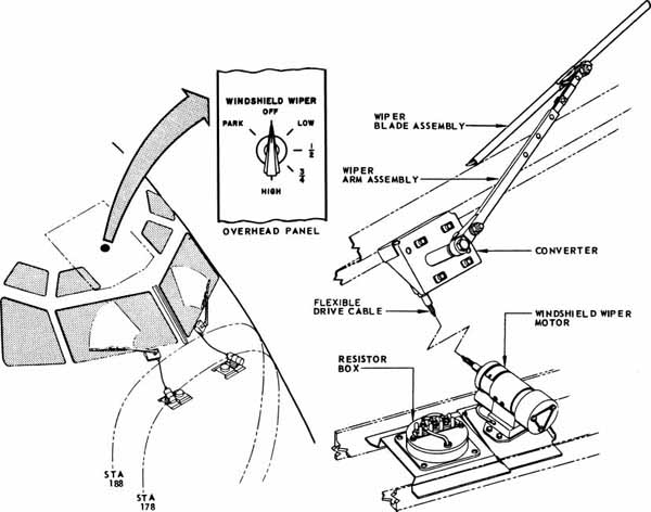
FIGURE 18-39 Windshield-wiper system. (Boeing Co.)
Both wiper systems are electrically operated and controlled by a common gang switch located on the pilot’s overhead panel. The switch provides a selection of four wiper-action speeds ranging from 190 to 275 strokes per minute and controls the stowing of the wiper blades in a PARK position when the system is not in use.
Each windshield-wiper system consists of a drive motor, a control switch, a resistor box, a flexible drive shaft, a torque converter, and a windshield-wiper assembly.
Speed control for the windshield wipers is accomplished by changing the voltage applied to the windshield-wiper motor by means of resistances arranged in the resistor box. The required resistance is connected into the motor circuit by turning the windshield-wiper switch to a selected speed. The rotary motion of the windshield-wiper motor is transmitted by the flexible shaft to the converter. The converter reduces the shaft speed and changes the rotary motion to an oscillating motion of the windshield-wiper arm. An electrical circuit for windshield wipers is shown schematically in Fig. 18-40.

FIGURE 18-40 Electrical system for windshield wipers. (Boeing Co.)
Rain-Repellent Systems
To help maintain the clarity of vision through the windshield during rain conditions, a rain-repellent system is provided for the windshields of many modern aircraft. This system consists of pressurized fluid containers, a selector valve, solenoid-actuated valves, spray nozzles, push-button switches, a control switch, a time-delay relay, and necessary plumbing. A rain-repellent system and windshield wipers for an airliner are shown in Fig. 18-41. During rain conditions, the windshield wipers are turned on, and the repellent is sprayed on the windshield. The repellent is spread evenly by the wiper blades. The rain repellent should not be sprayed on the windshield unless the windshield is wet and the wipers are operated, nor should the windshield wipers be operated on a dry windshield.
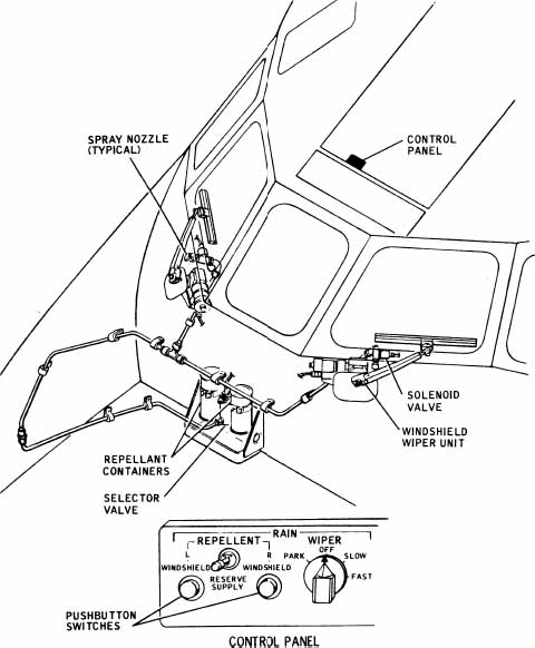
FIGURE 18-41 Rain-repellent system. (Douglas Aircraft Co.)
The effect of the rain repellent is to cause the water to form small globules, which are quickly blown away by the rush of air over the windshield in flight.
Flight deck windows of transport aircraft often use a permanent surface seal coating also called “hydrophobic coating” that is on the outside of the pilot/copilot windshield (see Fig. 15-41). The coating causes raindrops to bead up and roll off. This allows the flight crew to see through the windshield with very little distortion. The hydrophobic windshield coating reduces the need for wipers and gives the flight crew better visibility during heavy rain.
Pneumatic Rain-Removal System
Some turbine-powered aircraft use engine bleed air to prevent rain from striking the windshield. When the pilot turns on the rain-removal system, bleed air at a high temperature and pressure is directed to an outlet at the base of the windshield, as shown in Fig. 18-42. This flow of air over the windshield carries away the rain drops before they can strike the windshield. Any raindrops on the windshield when the system is turned on are also blown away.
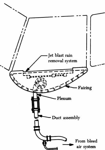
FIGURE 18-42 Pneumatic rain-repellent system.
WATER AND WASTE SYSTEMS
All modern airliners are required to incorporate water systems to supply the needs and comforts of the passengers and crew. Such systems include potable (drinkable) water for the galley and drinking fountains, water for the lavatories, and water for the toilet systems. Systems may include one or more tanks of water with connections to the various units that require a water supply. The passenger water system for one model of the Airbus 330 airplane is illustrated in Fig. 18-43.
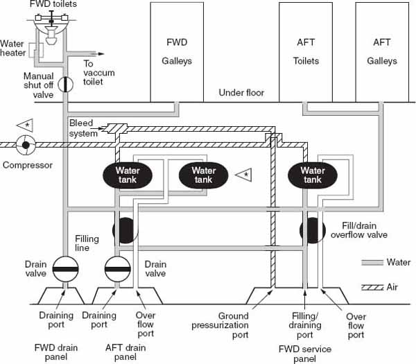
FIGURE 18-43 Passenger water system in Airbus 330.
Potable Water Supply
The water for drinking fountains or faucets is usually drawn from main pressurized water tanks, passed through filters to remove any impurities and solids, cooled by dry ice or other means of cooling, and delivered to the faucets and/or drinking fountains. Disposable drinking cups are supplied at each location in the forward and rear parts of the passenger cabin.
Lavatory Water
Water for the lavatories is also drawn from the main water tanks and passed directly through suitable plumbing and valves to the lavatories. Hot water for washing is provided by means of electric water heaters located beneath the lavatory bowls. A typical hot-water supply is contained in a 2-qt [1.89-L] tank, which includes the thermostatically controlled heating unit to maintain the water at a temperature of 110 to 120°F [43.3 to 48.9°C]. Drain water from the lavatories can be drained overboard through drain masts or can be drained into the toilet waste tanks.
Toilet System
Differential pressure forces waste from toilet bowls into two storage tanks (see Fig. 18-44). On the ground, and at altitudes below 16 000 ft, a vacuum generator produces the necessary pressure differential. Clear water from the potable water system flushes the toilets. A flush control unit in each toilet controls the flush sequence. The vacuum system controller (VSC) furnishes operational information (including the waste level in the storage tank) to the flight attendant’s panel, and maintenance information and a test program to the centralized maintenance system. The waste tank has a total capacity of 700 L. Ground personnel services the waste tank through a single service panel under the fuselage. A manual shutoff valve on the lower right-hand side of the toilet bowl isolates an inoperative toilet.
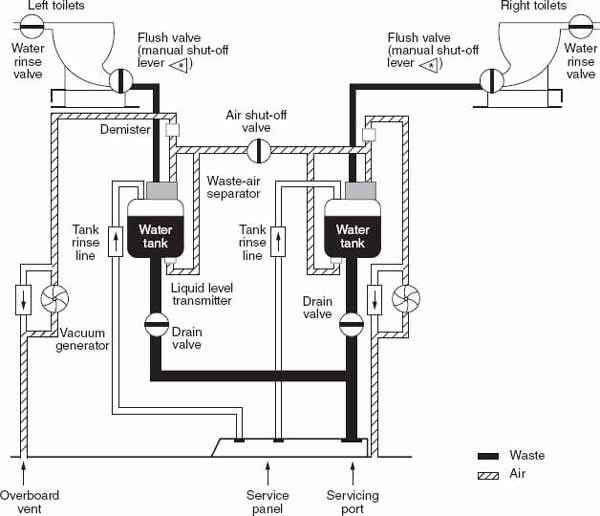
FIGURE 18-44 Toilet waste water schematic.
POSITION AND WARNING SYSTEMS
Each aircraft system may incorporate a warning system to indicate when that particular system is not functioning properly. The purpose of this section is to discuss systems that do nothing but indicate the position of components and warn of unsafe conditions. These systems include control-surface indicator systems, takeoff warning systems, and stall warning systems.
Control-Surface Indicating Systems
The purpose of control-surface indicating systems is to allow the flight crew to determine if a control surface is in the correct position for some phase of flight and to determine if a flight control is moving properly.
The most common type of control-surface indicating system is that used for the elevator trim tab, and this will serve as an example for other mechanical indicating systems. This type of mechanism is found in most fixed-wing aircraft and is used by the pilot to indicate if the trim tab is properly positioned for some phase of flight, such as takeoff or landing, before that phase of flight is initiated. If the trim tab is out of position, the pilot may have to use large forces on the flight controls to achieve the desired action. If the trim tab is properly positioned, then it will provide most of the force necessary to hold a specific attitude and the pilot will need to make only small adjustments about the trimmed setting of the control surface.
These types of systems often use a mechanical indicator to show the control position. In some systems, a cable is attached to the control horn of the trim tab, and as the tab moves the cable pulls against a spring at the pilot’s position. As the spring is stretched or released by the movement of the trim tab, a pointer located where the cable connects to the springs moves along a scale, indicating the trim-tab position. In other systems a spiral groove in the trim-tab control wheel causes a pointer to move, indicating the position of the trim tab.
Either of these systems or similar system designs can be used to monitor the position of any flight-control surface. When inspecting these mechanical indicating systems, the technician should verify that the indicator agrees with the position of the surface being monitored.
Large aircraft may make use of electric control-surface indicating systems, such as the one shown in Fig. 18-45. In this system, synchro transmitters are located at each of the control surfaces. The voltage inducted into the armatures by their exciter windings is used at the synchro receivers to position the indicator pointers.
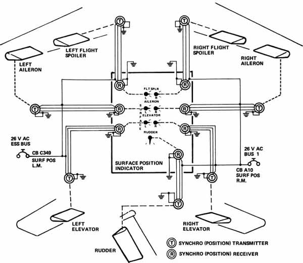
FIGURE 18-45 Flight-control-position indicating system for a jet aircraft. (Canadair Inc.)
Modern transport aircraft use glass cockpits and the electronic centralized aircraft monitor (ECAM) or EICAS system will display all control surface information on a monitor in the cockpit. Figure 18-46 shows the position of the spoilers, ailerons, elevators, elevator trim, and rudder.


FIGURE 18-46 Flight control indications on ECAM page.
Takeoff Warning Indicator Systems
A takeoff warning indicator system is used to advise the pilot that one or more items are not properly positioned for takeoff. When a takeoff warning system actuates, an intermittent horn is sounded until the incorrect situation is corrected or until the takeoff is aborted.
A simplified takeoff warning system schematic for a large jet transport is shown in Fig. 18-47. Note that if any one of the several items is not in the correct position for takeoff and the throttle for no. 3 engine is advanced beyond a certain position when the aircraft weight is on the landing gear, the horn will sound. The items that are checked by this system are that the elevator trim is in the takeoff range, the speed-brake (spoilers) handle is in the 0° position, the steerable fuselage landing gear is centered, the wing flaps are at 10°, and the leading-edge wing flaps are extended. The exact aircraft configuration monitored by a takeoff warning system will vary, but the intent of each system is to prevent a takeoff with the aircraft in an unsafe configuration.
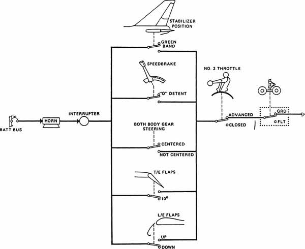
FIGURE 18-47 Takeoff warning system schematic for an airliner. (Boeing Co.)
In modern aircraft equipped with an EICAS system if the aircraft is in an unsafe takeoff configuration, configuration aural, warning messages, and MASTER WARNING lights come on. Figure 18-48 shows the different failure messages that could be displayed on the EICAS monitor.
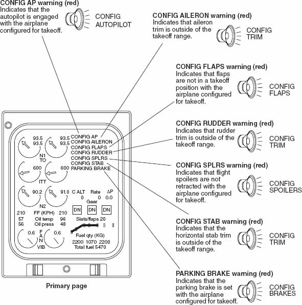
FIGURE 18-48 Takeoff configuration warnings.
Stall Warning Indicators
A stall warning indicator is designed to indicate to the pilot when the aircraft is close to the stalling angle of attack. When the stall warning system is activated, the pilot will be given one or more of the following indications: A horn will sound, a light will illuminate, and/or a “stick-shaker” will start vibrating the control wheel column. The specific warning method varies with the aircraft design.
Although some light aircraft do not have stall warning indicator systems, most have a system using a sensor vane on the leading edge of the wing similar to that shown in Fig. 18-49. When the angle of attack of the wing causes the airflow to be from below the vane on the sensor, the vane moves up and completes a circuit to activate the stall warning indicator.
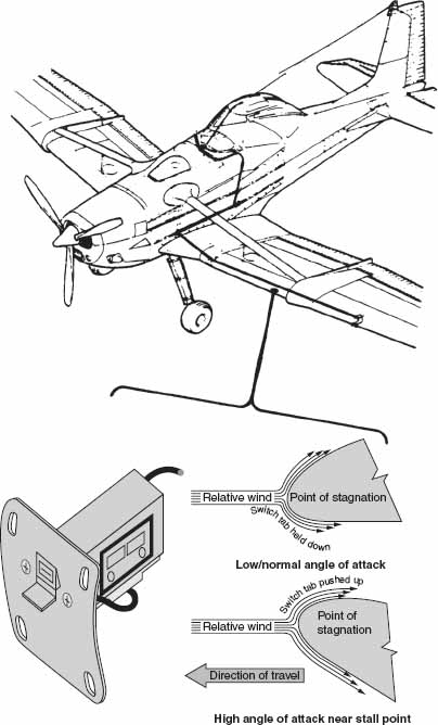
FIGURE 18-49 Stall warning indicator installation. (Cessna Aircraft Co.)
A pneumatic stall warning indication system is used by some light aircraft. A slot in the leading edge of the wing is connected to tubing routed to the cabin area. A horn reed is positioned in the end of the tubing. When the wing angle of attack increases to the point where a negative pressure exists on the slot, air flows through the reed and out the slot and creates an audible stall warning indication.
Modern transport aircraft use stall warning computer circuits to activate the stall warning system. Inputs to the computer include information about angle of attack, flap and slat position, and weight on landing gear. When the computer determines that a stall is imminent, a stick-shaker may start moving the control columns back and forth, an aural warning may be sounded, or an indicator may illuminate, depending on the specific system design.
AUXILIARY POWER UNITS
When a modern aircraft’s engines are not operating, there are two available sources of power to operate its other systems. They are the aircraft’s battery and the auxiliary power unit. Because of the limited capacity of the batteries, the amount of power they supply is insufficient to provide all but the very basic needs. Operation of an aircraft’s air-conditioning system, for example, would require significantly more power than could be supplied by the batteries.
To accommodate the needs of the aircraft on the ground for substantial amounts of energy while its engines are not operating, modern aircraft are equipped with auxiliary power units (APUs). The APUs are gas-turbine engines, using the aircraft’s own fuel supply, which provide the power to run the attached generators. In addition, the APU is typically large enough to provide sufficient pneumatic power to start the aircraft’s engines. The presence of an APU eliminates the need for ground power units (GPUs).
The Boeing 747 auxiliary power unit is manufactured by the AiResearch Division of Garret Corporation. This unit, shown in Fig. 18-50, is capable of producing approximately 660 lb/min airflow to the pneumatic systems and 90 kVA from the two attached generators to the aircraft’s electrical system. The APU has a separate battery for starting and is protected by its own fire-protection system.

FIGURE 18-50 Auxiliary Power Unit manufactured by AiResearch Division of Garret Corp., installed on a Boeing 747. (Boeing Commercial Aircraft Co.)
During operations, as with other gas-turbine engines, the exhaust is extremely high. In the case of the AiResearch APU previously identified, the exhaust-gas temperature (EGT) ranges from 1652°F [900°C] during starting to 1265°F [685°C] during normal operations. Extreme care should be taken before operating the APU to ensure the exhaust-gas flume area is clear.
The principles for operating a typical APU parallel those of other gas-turbine engines. A more detailed discussion of gas-turbine operations and associated systems of fuel, lubrication, and ignition is found in Aircraft Powerplants. A description of the electrical generating systems and controls used with gas-turbine engines may be found in Aircraft Electricity.
APU Operation and Control
Operating controls and indicating systems are typically separated by the functions they serve. The gas turbine operations and the control switch for the air bleed valve are found on the same panel; see Fig. 18-51. The APU operations panel usually includes controls for the APU start and stop, fire-protection test and indicating, and the fire extinguisher manual discharge discussed earlier in this chapter. Additionally, controls for the fuel valve and APU inlet doors may be found on the panel along with the typical engine operation indicators.
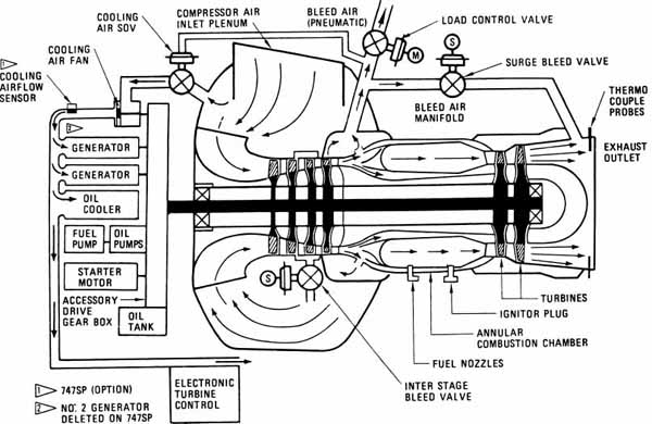
FIGURE 18-51 APU control and indicating panel. (Boeing Commercial Aircraft Co.)
The APU inlet door controls access to the gas-turbine compressor inlet and provides cooling air for the APU’s accessories. This door may be powered by an electric motor or may use the suction caused by the operation of the gas turbine to open a spring loaded door.
Airflow and Bleed Air
The amount of airflow and its pressure are dependent upon the ambient temperature and the load on (power being drawn from) the APU. The greater the load and/or ambient temperature the lower the airflow and pressure.
The air-bleed valve (Fig. 18-52) should be closed during start-up and not operated until the APU is at approximately 95 percent power. When the APU bleed valve, also referred to as the “load-control valve,” is opened by placing its switch in the cockpit in the OPEN position, airflow is supplied to the aircraft’s pneumatic power-distribution system.

FIGURE 18-52 Cross-section schematic of an APU. (Boeing Aircraft Co.)
Accessory cooling is provided from inlet air through a shut-off valve, which is closed unless there is a specified amount of pressure being discharged by the APU’s compressor.
REVIEW QUESTIONS
1. Which type of fire-detection system is termed a rate-of-rise detection system?
2. Describe the theory of operation of a spot detector and a thermocouple system.
3. Describe the different types of operation of a Systron-Donner pneumatic fire-detection system.
4. Which fire-extinguishing agent is used on most modern aircraft?
5. What devices are used as overheat or fire detectors?
6. Describe three types of tubular fire detectors, or sensors.
7. List the general features and capabilities of overheat and fire warning systems for aircraft.
8. How are overheat and fire warning systems tested for operational capability?
9. How can a crew member tell when the helium gas in a pneumatic sensor has been lost?
10. Describe the operation of the integrity monitoring circuit.
11. Explain the importance of correct routing for overheat and fire warning sensors.
12. How are sensors protected from vibration, wear, and damage?
13. Describe a toxic-gas detector.
14. What is the importance of a toxic-gas detector and what is a likely source of toxic gas in a light airplane?
15. In what areas of an airplane are smoke detectors most likely to be used?
16. Name three types of extinguishing agents used in aircraft fire-suppression systems.
17. Describe extinguishing-agent containers.
18. What gas is usually employed to expel the extinguishing agent from a container?
19. To what pressure is a container usually charged?
20. Describe the method by which the discharge head attached to a container releases the extinguishing agent.
21. What is used to indicate that a fire-extinguishing agent bottle has discharged thermally?
22. What are two classifications of fire-extinguishing systems?
23. What indicators are required to show the discharge of extinguishing agent?
24. What type of extinguishing agent should be used for electrical fires?
25. Discuss the need for portable fire extinguishers.
26. What parts of an airplane are subject to ice collection during icing conditions?
27. Describe a pneumatic-mechanical deicing system.
28. How are deicer boots attached to leading-edge surfaces?
29. How is air supplied to deicer boots?
30. Why is a conductive coating required for deicer boots?
31. For what conditions are deicer boots inspected?
32. Discuss the removal and replacement of deicer boots.
33. How is an operational test of a deicer system performed?
34. Describe the operation of a thermal anti-icing system on a large airplane.
35. What is the usual source of heat for thermal anti-icing?
36. What units are usually electrically anti-iced?
37. What methods may be used to keep a windshield free of ice?
38. Describe a rain-repellent system.
39. What is the purpose of a converter in a windshield-wiper system?
40. What may be used to power a windshield-wiper system?
41. What methods, other than wipers, may be used to remove rain from a windshield?
42. Describe the water system for an airliner.
43. By what method is water for the lavatory heated?
44. How is drinking water cooled?
45. Describe the operation of the toilet system.
46. By what method is flushing liquid forced through the system?
47. What is the purpose of a takeoff warning system?
..................Content has been hidden....................
You can't read the all page of ebook, please click here login for view all page.