

Fabrication and Repair of Wood Structures |
3 |
INTRODUCTION
Wood aircraft structures combine many of the attributes associated with metal and composite structures, such as light weight, low cost, and high strength, while requiring only the minimum of special equipment for proper maintenance and repair. For this reason, many of the lighter aircraft that have been produced have made use of wood primary and secondary components, such as wing spars, ribs, and control surfaces. A great many of these aircraft are still in operation, and a few designs are still in production using wooden structural components. Figure 3-1 shows aircraft which incorporate wood in their structures.
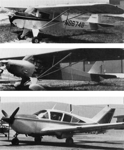
FIGURE 3-1 Airplanes having wood structures.
AIRCRAFT WOODS
There are two principal types of wood, hardwoods and softwoods, and all woods may be classed as one or the other. The distinction between hardwoods and softwoods is not based on the “hardness” of the wood but rather on the cellular structure of the wood.
Softwoods
Softwoods come from trees that have needlelike or scalelike leaves and are classified as evergreens or conifers. The wood of these trees is composed primarily of fibrous cells and has a smooth, even appearance when cut in cross section. Softwood has a high strength-to-weight ratio, which makes it a very desirable structural material for use in aircraft construction. Softwood is usually used as a solid wood for spars, cap strips, and compression members and as a veneer for plywood cores.
Woods included in the softwoods used in aircraft are Sitka spruce, Douglas fir, Port Orford white cedar, and western hemlock. Sitka spruce is the wood used as a reference material to establish the suitability of other softwoods for use in aircraft construction and repair.
Hardwoods
Hardwoods come from trees that have broad leaves and are classified as deciduous because they lose their leaves each fall. The wood of these trees is composed of a mixture of large cells, causing pores in the wood, distributed among the smaller fibrous cells. These pores are often visible when the wood is cut smoothly. Hardwoods are generally heavier than softwoods and are used where their strength advantage makes the extra weight acceptable over the softwoods. Hardwoods are commonly used as solid wood for support blocks and tip bows and as veneers for the facing and core material of plywood.
Hardwoods commonly used in aircraft structures include mahogany, birch, and white ash.
Terminology for Woods
Even though the aircraft technician may not have occasion to use standard terminology for woods very often, it is considered desirable to understand the terms illustrated in Fig. 3-2.

FIGURE 3-2 Nomenclature for woods.
Annual rings Concentric layers of wood that can be seen at the end of a tree trunk that has been cut perpendicular to its length. The rings are caused by the different rates of growth during each year as the seasons change.
Bark The external covering of a tree trunk or branch.
Check A radial crack that cuts across the grain lines.
Compression failures Wrinkles or streaks across the grain line caused by mechanical stress on the wood after the annual rings had grown. For detection, compression failures may require close examination with a light source aimed almost parallel to the grain structure.
Compression wood Deformed grain structure in the wood caused by mechanical stress on the tree, such as supporting the weight of a heavy limb, during growth. It is characterized by wide annual rings when compared to the normal size of the tree’s growth rings.
Decay A biological growth living off of the wood and causing a breakdown in the strength of the wood. Discoloration may also be present.
Grain The lines in wood caused by the annual rings. Grain also refers to the direction of the wood fibers.
Hard knot A knot that is firmly embedded in the wood and shows no sign of coming loose.
Heartwood The center part of a tree trunk, which is dead and carries no sap. This part of the tree serves only to support the tree.
Knot The base of a limb inside the tree. A knot will cause a deviation of the grain lines as they form around the knot.
Mineral streaks Coloring in the wood caused by minerals in the soil or other naturally occurring agents during the tree’s growth.
Moisture content The weight of water contained in a wood sample compared to the weight of the wood sample if all the water was removed from it.
Pin knot A knot resulting from the growth of a twig.
Pitch pocket Voids between the annual rings that contain free resin. These pockets are usually relatively small in cross section and are not to be confused with shakes, which can be extensive.
Sapwood The part of a tree that is alive or partially alive and carries sap. Sapwood begins immediately under the bark and extends to the heartwood. The sapwood is often lighter in color than the heartwood.
Shake A separation between the annual ring layers.
Spike knot A knot that was cut through parallel to the limb during the sawing operation such that the knot runs across the board.
Split A crack in the wood resulting from rough handling.
Springwood The soft, light-colored part of the annual ring.
This wood ring is normally wider than the summerwood ring because of the rapid tree growth during the spring season.
Summerwood The harder and usually darker part of each annual ring. This wood is formed during the slow summer season growth.
Evaluating Wood for Aircraft Use
The primary requirement for wood that is to be used in aircraft structures is that it be sufficiently sound and of such quality that it will provide the strength required for the structure. It has been determined through research that Sitka spruce is generally the best wood for use in aircraft structures because of its combination of lightness, strength, stiffness per unit weight, and toughness when compared to other species. Because of specific requirements, other species may be used due to unique qualities within the general evaluation criteria. The following paragraphs discuss the wood characteristics that the technician must consider when selecting wood of the desired species.
There are two classifications of water in wood, free water and cell water, as shown in Fig. 3-3. Free water is the water that flows up and down the tree carrying nutrients. Cell water is water trapped within the walls of the wood cells’ structure and is part of the structure of the tree. Aircraft woods are kiln-dried to remove all the free water and a portion of the cell water, so the resulting moisture content is between 8 and 12 percent. A moisture content above or below this range is not considered acceptable.

FIGURE 3-3 A wood cell before (left) and after (right) drying. When the cell water is removed, the wood shrinks and becomes stronger.
Kiln-dried wood is dried by placing the boards of fresh-cut wood in a precisely controlled oven and raising the temperature to a specified level for a specified period of time. Not only does this process reduce the moisture content to the desired level, but it also kills the insects and decay-producing organisms that may have infected the wood.
The specific gravity of aircraft woods should be from 0.34 to 0.40, depending upon the type of wood. Aircraft spruce should have a specific gravity of approximately 0.36.
The grain structure of the wood must be examined to determine if the wood has been properly cut, if the grain lines are sufficiently straight, and if there is a minimum number of annual rings per inch.
The way a board is cut is important, because this affects the strength of the piece of wood and the shrinkage characteristics of the wood. Ideally, aircraft solid wood should be cut so that the annual rings are parallel to the narrow dimension of the board. This is known as quarter-sawed, or edge-sawed, wood and is illustrated in Fig. 3-4. For practical purposes, a board is considered to be quarter-sawed if the annual rings are at an angle no greater than 45° to the narrow dimension.

FIGURE 3-4 This illustration shows two methods of cutting a log to obtain quarter-sawed wood.
The slope of a grain line is determined by looking at the side of a board and noting the angle that the grain line makes with the edge of the board. Ideally, the grain lines will be parallel to the edge of the board, but a deviation or slope of 1:15 is allowed. This means that a grain line starting at the edge of the board may not move more than 1 in [2.54 cm] from the edge of the board when it is 15 in [38.1 cm] from the starting point, as shown in Fig. 3-5.
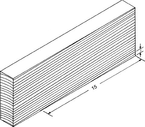
FIGURE 3-5 The maximum slope allowed in aircraft wood is 1:15.
The number of annual rings per inch, or grain count, is another criterion that must be checked for aircraft-quality wood. The grain count is taken by counting the number of grain lines (annual rings) per inch on the sample. This is best done by looking at the end of a board and measuring a 1-in [2.54-cm] line perpendicular to the annual rings. The minimum grain count for most softwoods is six rings per inch [2.54 cm], with the exception of Port Orford white cedar and Douglas fir, which must have a minimum of eight rings per inch [2.54 cm].
When evaluating wood, the following defects are not acceptable: checks, shakes, splits, decay, compression wood, compression failure, and spike knots. Defects that might be acceptable, depending on their size, location, and condition, are hard knots, pin knot clusters, mineral streaks, and irregularities in grain direction. Evaluation criteria for these defects are given in Table 3-1.

Specifications for aircraft woods as given in Federal Aviation Advisory Circular (AC) 43.13-lB provide that certain minor defects, such as small solid knots and wavy grain, may be permitted if such defects do not cause any appreciable weakening of the part in which they appear. As a practical rule, aircraft technicians should not use any wood about which they have doubts. The safe policy is to use wood that is straight-grained, free from cracks, knots, or any other possible defect, and guaranteed as aircraft-quality.
Wood Substitutions
When repairing or rebuilding wood components, species substitution may be allowed if the structural strength of the component is not reduced. Table 3-2 shows types of wood that may be considered for substitution, with spruce being the reference wood. Note that the choice of a substitution may have to take into account changes in size, different bonding qualities, and different working qualities.

Plywood
Plywood is composed of an uneven number of layers (plies) of wood veneer assembled with the grain of each layer at an angle of 45° to 90° to the adjacent layers. The outside layers are called the faces, or the face and back, and the inner layers are called the core and crossbands. The core is the center ply, and the layers between the core and outer layers are the crossbands.
The layers of plywood are bonded with special adhesive of the synthetic resin type such as phenol formaldehyde adhesive. Flat aircraft plywood is usually assembled with a thermosetting (hardened by heat) adhesive in a large, heated hydraulic press. It must be emphasized that aircraft plywood is of much higher quality than commercial grades. Every layer of wood in a sheet of aircraft plywood must be of excellent quality to provide for uniform strength throughout.
Plywood has a number of advantages over solid wood in that it is not likely to warp, it is highly resistant to cracking, and its strength is almost equal in any direction when stresses are applied along the length or width of a panel. Its change in dimension is negligible with changes in moisture content.
The most commonly used types of plywood for aircraft manufacture are mahogany and birch. The core and crossbands may be made of basswood or a similar wood that provides adequate strength. Mahogany has a reddish-brown appearance, whereas birch is of a light yellow or cream color. Mahogany offers a better bonding surface than birch because of its porosity.
When selecting or ordering plywood for aircraft use, the technician should make sure that the wood is of aircraft quality. Some commercial plywoods appear to be as good as aircraft plywood; however, it will be found that the quality is only on the surface and the strength does not compare with the aircraft-quality product.
Laminated Wood
Laminated wood is several layers of solid wood bonded together with an adhesive. Laminated wood differs from plywood in that each layer of wood has the grain running in the same direction, whereas plywood has the grain direction of each layer at a large angle to the previous layer. Laminated wood tends to be more rigid than a piece of solid wood of the same size and is much more resistant to warpage. Laminated wood is used for components that require a curved shape, such as wing-tip bows and fuselage formers, and is used in place of solid wood, such as for solid-type wing spars.
ADHESIVES AND BONDING PROCEDURES
Adhesive are used almost exclusively for joining wood in aircraft construction and repair. A part is regarded as satisfactorily bonded if the strength of the joint is equal to the strength of the wood. In a strong joint, there is complete contact of adhesive and wood surfaces over the entire area of the joint and a thin, continuous film of adhesive between the wood layers unbroken by foreign particles or air bubbles.
To accomplish satisfactory bonding in aircraft wood structures, it is necessary that a number of exacting rules be observed and that all materials be of the high quality specified for aircraft woodwork. If either the adhesive or the wood is not of satisfactory quality or if the techniques employed are not correct, the bonding operations will be inferior and may result in failure.
Types of Adhesives
There are two broad categories of adhesive used in aircraft wood structure, casein and synthetic resin. The synthetic resin adhesives are commonly used in modern construction and repair operations.
Casein adhesives are manufactured from milk products, are highly water-resistant, and require the addition of sodium salts and lime to prevent attack by microorganisms. Casein adhesive should not be used anymore due to inferior performance. Synthetic adhesives should be the first option for bonding wood structure.
Synthetic adhesives are of the urea formaldehyde, resorcinol formaldehyde, phenol formaldehyde, and epoxy types. Depending on the formulation of the adhesive, it may be water resistant or waterproof and may be purchased in a liquid or powdered form. Synthetic adhesives are not attacked by microorganisms. Resorcind is the only known adhesive which is recommended and approved for use in wood aircraft structures and which fully meets necessary strength and durability requirements. Epoxy adhesives are acceptable and many new epoxy resin systems appear to have excellent working properties and are less critical of joint quality and clamping pressure.
Mixing Adhesives
The mixing of adhesives must be done in accordance with the adhesive manufacturer’s instructions to ensure that the full strength of the adhesive will be available. The following discussion is meant to present guidelines for mixing adhesive so that the technician will have an idea of mixing requirements.
The container used for mixing adhesive must be of a material that will not react with the chemicals that make up the adhesive. The container and mixing tools must be clean and free of any contaminants or old adhesive.
In preparation for mixing, the ingredients are measured out in the proper proportions. These proportions may be either by weight or by volume. The ingredients may include powders and liquids, purchased as part of the adhesive, and water. The sequence of mixing may call for the powder to be added to water, water to be added to the powder, or two liquid components to be mixed in some specific sequence, such as adding a liquid catalyst to a liquid adhesive.
For mixing adhesive properly, the room temperature generally must be at or above 70°F [21°C]. The process of mixing the adhesive requires that the speed of mixing be slow enough so that air is not whipped into the mixture. Air would result in a weak adhesive joint. Once the adhesive is mixed, it may have to stand for some period of time to allow the components of the adhesive to interact before a proper adhesive joint can be formed.
Once the adhesive is ready to be used, it has a specific working life, during which it can be applied with assurance that a proper adhesive bond will form. This time is influenced by the room temperature, with higher temperatures resulting in a shorter working life. If the ambient temperature is high, the working life of the adhesive can be extended by placing the adhesive container in a water bath of cool water (no lower than 70°F [21°C]). The average working life of adhesives is 4 to 5 h at 70°F [21°C].
Surface Preparation for Adhesive Bonding
To ensure a sound adhesive bond, the wood must be properly prepared to allow full surface contact between the components being joined. The condition of the wood must be such that the adhesive bonds properly with the surface of the wood. This includes being free of any surface contaminants and having the proper moisture content.
Wood surfaces to be bonded should be smooth and true. Chapped or loosened grain, machine marks, and other surface irregularities are objectionable. Joints of maximum strength are made between two planed or smoothly sawed surfaces that are equally true.
Although the wood surface must be true prior to bonding, the method of obtaining this trueness may affect the strength of the bond. For example, softwoods should not be sanded when preparing the surface for bonding. Sanding fills the wood pores with wood dust and prevents the adhesive from properly penetrating the surface. However, hardwoods can be sanded prior to bonding without any detrimental effects on the adhesive bond. With either type of wood, filing and planing are considered proper methods to prepare the surface for bonding. There should be no more than 8 h between the time that the surface is prepared for bonding and the bonding operation takes place.
The surface to be bonded should be free of any paints, oils, waxes, marks, or particles that would interfere in any way with the proper bonding of the adhesive to the wood surface. The presence of wax on a surface can be detected by placing water drops on the surface. If they bead up, then wax is present and must be removed prior to bonding. This may be particularly useful in determining the surface condition of plywoods that may have been protected with a waxed paper.
The moisture content of wood when it is bonded has a great effect on the warping of bonded members, the development of checks in the wood, and the final strength of the joints. A moisture content at the time of bonding that is between 8 and 12 percent is generally regarded as satisfactory, but the higher the moisture content within this range, the better will be the joint. If the moisture content is too low, the adhesive cannot wet the surface properly, and it sometimes produces what are called starved joints—that is, joints not adequately bonded. Bonding increases the moisture content of the wood; therefore, the moisture added in this manner must dry out or distribute itself in the wood before the part can be machined or finished. Other factors in establishing moisture content are the density and thickness of the wood, the number of plies, the adhesive mixture, and the quantity of adhesive used.
Adhesive Bonding Procedures
A strong joint in the wood is obtained from complete contact of adhesive and wood surfaces over the entire joint area and a continuous film of good adhesive between the wood layers that is unbroken by air bubbles or by foreign particles. Under these conditions, the adhesive penetrates the pores of the wood and forms a bond that is stronger than the bond between the original wood fibers. When broken, such a joint will not separate at the adhesive bond but will fracture in the wood outside the bond.
Adhesive should be spread evenly over both surfaces forming the adhesive joint. Either a brush or a soft-edged spreader may be used to apply the adhesive. If a brush is used, careful inspection must be made after spreading the adhesive for any bristles that may have broken off.
Two different assembly methods may be employed in joining wood parts with adhesive. The open assembly method is often recommended because it reduces the time required for the adhesive to set up. In open assembly, the adhesive is applied to both surfaces to be joined, and the parts are not put together for a specified length of time. If pieces of wood are coated with adhesive and exposed to a free circulation of air, the adhesive thickens faster than when the pieces are laid together as soon as the adhesive is spread. This latter process is called closed assembly.
In bonding operations, the assembly time may be as little as 1 min or as long as 20 min, but the adhesive must remain at a satisfactory consistency throughout the period. Unless specifically stated to the contrary by the manufacturer of the adhesive, open assembly should not permit the adhesive to be exposed to the open air for more than 20 min.
Bonding Pressure
The functions of pressure on an adhesive joint are as follows: (1) to squeeze the adhesive into a thin, continuous film between the wood layers, (2) to force air from the joint, (3) to bring the wood surfaces into intimate contact with the adhesive, and (4) to hold the surfaces in intimate contact during the setting of the adhesive.
A light pressure is used with thin adhesive and a heavy pressure is used with thick adhesive. Corresponding variations in pressure are made with glues of intermediate consistencies. The pressure applied should be within the range approved for the types of wood being bonded. For example, the bonding pressure should be between 125 and 150 psi [861.75 and 1034.25 kPa] for softwoods and between 150 and 200 psi [1034.25 and 1378.8 kPa] for hardwoods.
The method of applying pressure depends on the size, shape, and contour of the surface. Pressure can be applied by the use of clamps, nails, weights, nail strips, or screws.
Bonding Temperature
Temperature of the bond line affects the cure rate of the bonded joint. Some adhesives require a minimum temperature to cure. Always follow the manufacturer’s recommendations.
CONSTRUCTION AND REPAIR OF WOOD STRUCTURES
Before attempting to repair a damaged wooden aircraft structure, the technician must understand the nature of the required repair and have the correct materials and technical information required at hand to make the repair.
Nomenclature for Wooden Aircraft
The nomenclature for a wooden wing is shown in Fig. 3-6. Note that the parts are named according to standard practice for both metal and wooden wings. In the illustration, the leading-edge strip, the plywood skin, and the corner block are unique to wooden wing construction. Some of the nomenclature for a wooden fuselage is given in Fig. 3-7. Here again, the nomenclature is similar to that given for a metal fuselage of the semimonocoque type.
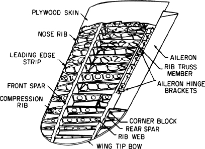
FIGURE 3-6 Nomenclature for a wooden wing.
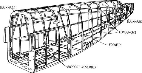
FIGURE 3-7 Nomenclature for a wooden fuselage.
Bending and Forming Wood
Bending of wood is necessary to achieve the desired shape of components while maintaining the structural strength of a straight piece of wood. Any type of wood may be bent, with the degree of shaping depending upon the size of the piece, the type of wood, and the technique used in preparing the wood for bending.
Solid wood is normally bent only over a very large radius and then only when the wood is of a small cross-sectional area. Only the best, clearest, straight-grained material should be considered for bending. Woods commonly used for bent components include spruce, ash, and oak. Typical airframe components made of bent solid wood include wing-tip bows, rib cap strips, and fuselage stringers.
Laminated wood structures are commonly used to form any severely bent structure because of the ease with which the thin laminations can be formed and because of the high strength of the finished laminated structure. Laminated members, since they have a parallel grain construction, have about the same properties as solid wood, except that laminated members are usually more uniform in their strength properties and less prone to change shape with variations in moisture content. Curved laminated structures are used for items such as tip bows, formers, and bulkheads.
Plywood is formed to make leading-edge coverings and surface panels. Most curved plywood components start out as flat sheets and, through various bending operations, are formed to the desired shape. While solid and laminated structures are normally bent in only one direction, plywood is often bent in two planes by stretching it over formers, resulting in a double curvature. This double curvature is often found in areas such as fairings and wing tips.
Wood may be bent in a dry condition or after being soaked in water for some period of time. Dry bending allows the least amount of bending, whereas soaking the wood in cold water makes the wood more flexible. To increase the flexibility of the wood, it can be soaked in hot water or, for maximum flexibility, it can be heated in a steam chamber. The wood should be exposed to the steam for 1 h per inch [2.54 cm] of thickness, with a maximum of 4-h exposure. Excessive heating causes the wood to break down structurally.
Immediately after steaming, the wooden part must be bent. If the curvature is slight, the part may be bent by hand over a form of the desired shape. If the curvature is pronounced, most of the deformation (change of shape) is accomplished by compression or shortening. This is done by using a forming die and holding strap, such as the one illustrated in Fig. 3-8. The wood to be bent is fitted snugly between the bulkheads shown in the picture and then bent over the forming die. In some cases, the type of clamp shown in the lower drawing of Fig. 3-8 does not hold. It is then necessary to use a vise-type clamp with outer and inner forming dies.
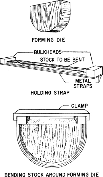
FIGURE 3-8 Using a forming die and holding strap.
The wood, having been bent, should remain in the forms until it has cooled and dried enough to keep its shape. The forms are usually made with a slightly greater curvature than that required for the finished part to provide for the tendency of the wood to straighten out somewhat after it is taken out of the forms. In addition, the forms should be designed so that they expose as much as possible of the bent piece to the drying effect of the air.
Laminated wood members that do not require severe bending, such as wing-tip bows, may be formed without steaming or any other softening preparation. If the laminations are thin enough to take the necessary bend without splitting, they are cut to size and planed on both sides. Laminations sufficient in number to make up the required thickness are coated with adhesive and clamped in a form of the necessary shape. Time is allowed for the adhesive to set and for the wood to dry thoroughly, after which the wooden part will retain the shape of the form. If there is any springback, it will be very slight. In certain cases, where it is not desirable to use very thin laminations or where the bending curvature is severe, the laminations may be steamed and bent to shape before being bonded together. A laminated component in a jig is shown in Fig. 3-9.
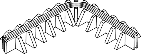
FIGURE 3-9 A laminated wood structure is normally held in a jig until the adhesive dries.
When curved plywood members are needed, several layers of veneer may be bent and bonded in one operation, or the prepared plywood may simply be bent.
When built-up plywood members are desired, veneer strips or sheets are bent over a form after adhesive has been applied to their surfaces. The sheets or strips are held together, often with staples, while the adhesive sets; the member then retains its shape after it has been removed from the form. The grain of each successive layer of veneer should be perpendicular to that of the adjoining layer, but in some jobs the veneer is applied on the form with the grain running at an oblique angle of about 45° from the axis of the member. If the work is done carefully, a built-up plywood member should have about the same properties as a bent laminated member.
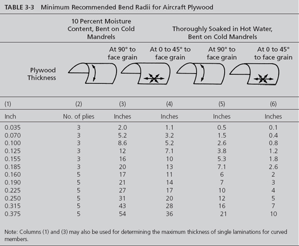
The degree to which plywood may be bent is illustrated in Table 3-3. Note that if plywood is selected with the grain lines 45° to the face grain rather than 90° to the grain line, then a sharper bend is possible. Also note that the greater the number of veneers in a plywood of a given thickness, the sharper the bend that is possible.
Wing Spar Construction
Wooden wing spars are constructed using several different techniques, depending on the size of spar required and the structural strength requirements. Some aircraft may include several different construction techniques along the length of one spar as the required structural strength changes.
Based on the materials used in the structure, spars can be divided into two broad categories: solid spars and built-up spars.
Solid spars use solid wood as the primary components. These spars may be made of one piece of wood that is rectangular in cross section, several pieces of solid wood laminated together, an externally routed solid piece, or an internally routed spar formed by routing out portions of two boards and then joining the routed sides of the boards together to form a spar. Examples of these different types of solid spars are shown in Fig. 3-10. Solid spars may change in their external dimensions along their length, may have areas that are not routed, such as at fittings, and may include plywood plates attached to areas requiring reinforcements, such as at fitting attachments.

FIGURE 3-10 Solid and laminated spars.
Built-up spars include a combination of solid wood and plywood components. Built-up spars can be divided into three basic types—C-beam, I-beam, and box-beam—as illustrated in Fig. 3-11. C-beam and I-beam spars consist of a plywood web as the principal vertical member running the length of the spar. At the top and bottom of this web are located solid wood cap strips. For a C-beam, the cap strips are on only one side of the spar, whereas an I-beam has cap strips on both sides of the web. Intercostals are located vertically between the cap strips at intervals to increase the strength and rigidity of the spar. Blocks are used between the cap strips to allow for the attachment of fittings.
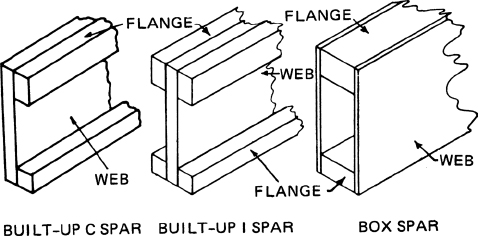
FIGURE 3-11 Built-up spars.
A box-beam spar consists of a top and bottom solid-wood cap strip, plywood webs on the outside of the cap strips, and intercostals and blocks used for strength, stiffness, and attachment of fittings.
Spar Repairs
When a spar is damaged, the damage must be evaluated to determine if the spar can be repaired or if it must be replaced and what the economic factors are concerning the cost of a repair versus the cost of replacement. The economic factors must be decided between those doing the repair and the aircraft owner. Factors that determine the repairability of a spar include the existence of any previous repairs, the location of the damage, and the type of damage. If a spar has been repaired twice, it is generally considered to be unrepairable. If the damage is in such a location that a splice is not possible without interfering with wing fittings, as discussed later, then the spar is unrepairable. If the damage is such that the integrity of the repair will be in doubt, such as the presence of extensive decay, then the spar is unrepairable. Keep in mind that each spar must be evaluated, and no one set of rules can apply to all spars.
If a spar is determined to be repairable, the repair procedures outlined in the aircraft’s maintenance manual or in AC43.13.1B should be followed. Figure 3-12 is an example of a repair of a wooden wing spar.
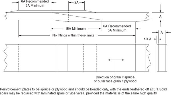
FIGURE 3-12 Example of repair of a solid or laminated wooden wing spar.
Rib Construction
Ribs give the wing and other airfoil sections the desired cross-sectional shape. In some wings, certain ribs take the compression load between the front and rear spars, in which case they replace the compression struts that would otherwise be used to separate members. A tapered wing may be tapered in width, tapered in thickness, or tapered in both thickness and width. Therefore, the ribs of tapered wings vary in size from wing tip to wing root, although the cross-sectional shape (airfoil section) of each rib is the same throughout in most designs.
Some ribs are built with the nose section, the center section between the spars, and the trailing-edge section as separate units, all being butted against the spar and fastened with adhesive and nails. Other ribs are constructed in one unit and slipped over the spar to their proper stations.
The rib structure may consist of the truss type with plywood-gusseted joints, the lightened and reinforced plywood type, the full plywood-web type with stiffeners, or some other special design. It is very important that no change be made in the shape of an airfoil section during construction or repair.
When making replacement ribs, it is best if they are made from a drawing furnished by the manufacturer or from a drawing made by a repair agency and certified correct by the manufacturer. However, an original rib may be used as a pattern for making a new rib if the original rib is not so badly damaged that comparison is inaccurate.
A wood rib is usually assembled in a rib jig. The rib jig is made by drawing a pattern of the rib on a smooth, flat plank and then nailing small blocks of wood to the plank so that they outline the rib pattern. During assembly, the cap strips are inserted between the blocks to hold them in the proper position for attachment of the vertical and diagonal members and the plywood gussets. Gussets are attached to the cap strips, verticals, and diagonals with nails and adhesive. Figure 3-13 shows a rib assembled in the jig and a completed rib.

FIGURE 3-13 Rib jig and completed rib.
The components of the rib are cut so that they are a “push” fit, with perfect alignment between all contact surfaces. There should not be any visible gap between components, and none of the components should require more than a gentle push to position them onto the jig board.
Once all the components are cut and their fit is checked by positioning them on the jig, adhesive is applied to all the contact surfaces and the rib is assembled in the jig. Nails are used to apply pressure to the adhesive joints covered by the gussets. Once the adhesive has set, the rib is removed from the jig, excess adhesive is removed, and gussets are added to the opposite side of the rib. The rib is finished first by filing down any overhang of the gussets and then by varnishing the rib. Care must be exercised to prevent any varnish from getting on the wood in the areas where the rib will be bonded to the spars.
When a rib must be repaired or installed on a wing that is already assembled, it is usually necessary to build the rib on the wing. This requires great precision to make sure that the rib is the same shape and size as the original. To do this, a rib jig can be constructed, cut into sections to fit around the spars, and positioned on the wing to allow a rib to be built in place, as shown in Fig. 3-14.
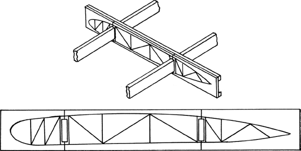
FIGURE 3-14 Rib jig placed on wing spars.
Wood ribs are commonly attached to the spar by the use of adhesive and then nailing the rib to the spar through the vertical members of the ribs. Ribs should not be attached by nailing through the rib cap strips (top and bottom pieces), as this will significantly weaken the ribs. Some rib installations make use of comer blocks bonded and nailed to the spars and the ribs to hold the ribs in position. After the ribs are attached to the spars, a cap strip may be placed on the top and bottom of the spars between the ribs to further stabilize the ribs on the spars. Figure 3-15 shows an example of acceptable wing rib repairs.
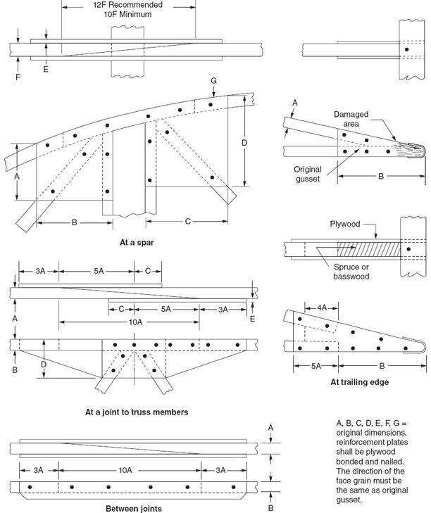
FIGURE 3-15 Repair of wood ribs.
Leading- and Trailing-Edge Strips
The leading edge of a wing, of an aileron, or of other airfoil surfaces may be provided with special nose ribs, stiffeners, and a covering of sheet metal or plywood to maintain its shape and carry local stresses. A metal or wooden strip is often used along the leading edge to secure the ribs against sidewise bending and to provide a surface for attaching the metal, fabric, or plywood covering. In some airplanes, the metal or plywood covering acts as the stiffener for the ribs instead of the leading-edge strip.
Figure 3-16 shows the use of a template in shaping the leading edge. The curved portion of the leading-edge strip completes the contour along the nose of the wing. It is important in forming the leading edge of the strip to use a template, corresponding to the curvature, for checking the work.
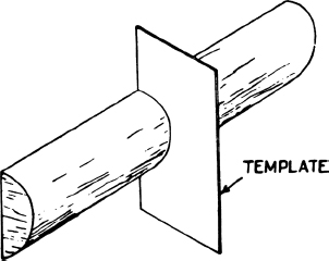
FIGURE 3-16 A template used to shape the leading edge.
The trailing-edge strip of an airfoil surface may be of wood or metal. The wooden strip is made similar to the leading-edge strip. Templates may be used to indicate the camber of the rib.
The leading edges of wing and control surfaces are repaired by carefully made and reinforced splices, such as the one illustrated in Fig. 3-17, where a damaged leading-edge section of a horizontal or vertical stabilizer is repaired by splicing in a new section. To obtain additional bonding area, the skin is feathered into the strip. If this is done properly, only one reinforcing strip is required.
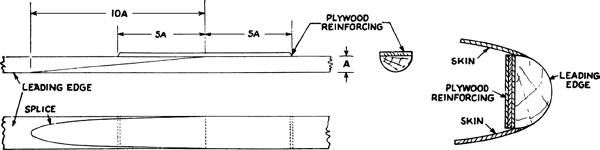
FIGURE 3-17 Repair of a damaged leading-edge section.
Wing-Tip Bow Construction and Repair
A wing tip may have any of several shapes. For example, it may be square, elliptical, or circular in plan form. If the wing tip is elliptical or circular, a wooden or metal wing-tip bow is required for attaching the plywood or fabric covering. A wooden bow for this purpose may be made of solid wood or laminations and bent to the required shape.
Figure 3-18 shows three types of wing-bow cross sections with the plywood surface and the tip bow indicated in each.

FIGURE 3-18 Wing-bow cross sections.
A wing-tip bow that has been badly damaged should be removed and replaced. A cracked or broken bow may be repaired by splicing in a new piece. The new piece may be spliced in at the spar. It should have the same contour as the original bow, and the splices should meet the requirements of a scarf joint.
Installation of Plywood Skin
Plywood for the skin of the airplane is cut and shaped to fit the surface to be covered, enough material being allowed to provide for scarfing (tapered-edge joints) where needed. Depending upon the design, it may be necessary to cut the skin larger than is needed and to trim it to size after it has been bonded to the frame, particularly in the case of wing tips.
The next step is to nail the plywood temporarily to the frame in one corner, make any required adjustments, and then nail in the opposite corner. These temporary nails are driven through small strips of wood so that they can be pulled out easily. The corners having been secured, the plywood is then pressed down against the framework with the hands to be sure that it is in the exact position and that all supporting members, such as ribs and spars, are properly contacted.
If possible, the plywood is then marked on the inside so that the areas of contact with the internal structure are identified. The plywood is then removed and adhesive is applied to the contact area of the structure, which is indicated by the drawn lines on the plywood. The plywood is then carefully placed back on the structure and secured with nailing strips.
The nailing strips used to hold the plywood in place until the adhesive sets are strips of wood about  to
to  in [5 to 6 mm] thick and
  in [12.7 mm] wide. The strips are first nailed near the center of the skin panel and then nailed outward in both directions. More nailing strips are applied, this time perpendicular to the first set, starting near the middle and working outward in whichever direction will avoid wrinkles and permit the plywood to lie smooth.
The nails are driven down tightly, and enough nailing strips are used to cover the entire surface of the supporting members. The width of the supporting member determines the number of nailing strips required. One nailing strip is used on surfaces in [12.7 mm] wide. Several nailing strips, laid side by side, are used for covering wider surfaces.
The nails are driven so that those in one strip alternate with regard to those in an adjacent strip. If the plywood skin is from  to
to  in [1.59 to 2.38 mm] thick,
  -in [15.88-mm] nails spaced at -in [38.1-mm] intervals are used for holding the skin to the ribs. The object is to space the nails as close together as possible without splitting one of the parts being bonded. Whenever nailing strips come into contact with the adhesive, waxed paper is placed under the strips to prevent them from being bonded to the member.
When a leading edge is to be covered, the plywood is first cut to the approximate size of the section to be covered. The leading edge is then bent over a form or over the wing leading edge. It is often necessary to soften the wood by soaking or steaming it prior to the bending operation. The plywood is held in place over the form or leading edge with shock cords, rubber straps, or any other apparatus that will provide an even pressure over the surface of the plywood without distorting the plywood or damaging the leading-edge structure.
When the plywood is thoroughly dry, the formed piece is fitted again and cut to the precise size. Adhesive is applied to the framework (nose ribs, spar, etc.) and the formed plywood. The plywood is placed on the frame and pressure is applied by means of nailing strips. These nailing strips may be started along one edge of the spar or along the leading-edge strip. More nailing strips are then laid over the nose ribs, starting with the center rib and working toward each end of the wing section. Soaking the nailing strips in warm water to make them bend more easily is a good treatment for those nailing strips laid over the curved portion of the leading edge.
Although nailing strips usually provide a satisfactory method for applying pressure to adhesive joints when installing plywood skins, other methods are also used, and some of these may be more effective than the nailing strips. One of these methods is to place a heavy piece of web strap around a wing immediately over a rib and the plywood after the adhesive has been applied. The strap is then tightened until the plywood skin is pressed firmly against the member to which it is being bonded.
Another method that can be used is to apply pressure to the plywood over an adhesive joint by means of shot bags or sandbags. Great care must be exercised to make sure that the plywood is pressed against the structure to which it is being attached and that there is a good adhesive film in all joints.
Repair of Damaged Plywood Structures
When the stressed plywood skin on aircraft structures requires extensive repairs, it is essential that the manufacturer’s instructions be followed carefully. When the repair is made according to manufacturer’s specifications, the original strength of the structure is restored.
Before proceeding with any repair operations, the type and extent of damage to a plywood skin and the internal structure should be evaluated. Information that should be taken into account in determining whether repair or replacement is necessary and the type of repairs possible include the location of the damage, the size of the damaged area, the thickness of the plywood, whether the plywood has a single or double curvature, and the location of and damage to internal structural components.
If internal components are damaged then enough of the plywood covering must be removed to allow for access to and proper repair of these internal components. The repair of internal components should follow the guidelines established for spars and ribs, replacing or splicing in new sections by the use of scarf splices and reinforcement plates.
The curvature of the plywood must be determined if the damage area is of any significant size. If a piece of paper can be laid on the surface and smoothed out without wrinkling, then the plywood has a single curvature (bent in only one direction) and preparing a replacement panel will not require any special equipment. If the paper cannot be laid on the surface without wrinkling, then the plywood has a double curvature. If this is the case, a replacement panel must be obtained from the manufacturer or manufactured by the use of a mold or form and some sort of pressure mechanism to achieve the double curvature.
There are five repair procedures for plywood skin that can be used. They vary in complexity, and their use may be restricted based on the location of the damage, size of the damaged area, and thickness of the plywood, as shown in Table 3-4. Figure 3-19 shows an example of a scarf repair and Fig. 3-20 shows an example of a splayed patch.

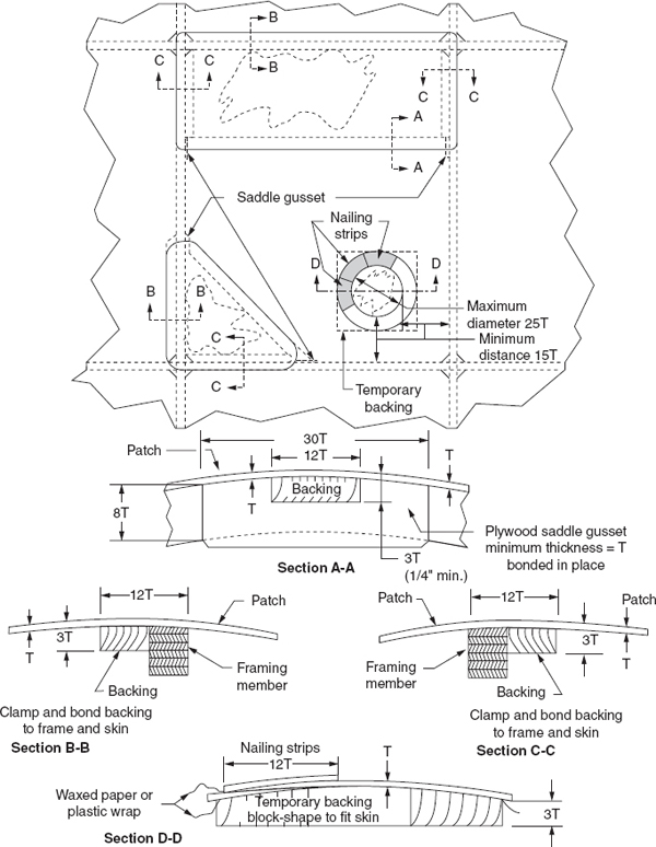
FIGURE 3-19 Example of scarf repair.
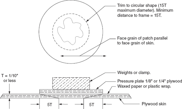
FIGURE 3-20 Example of splayed patch.
Fiber Insert Nut Plates
Fiber insert nut plates are installed at various locations in the wings and fuselage for the attachment of inspection doors, fuel-tank cap covers, and other parts. If one of these nuts is damaged or if a machine screw breaks off in it, the portion of the wooden strip carrying the nut and extending about 1 in [2.5 cm] on each side should be sawed out and replaced by a new section that is bonded and nailed in place. These nut strips are  -in [9.53-mm] plywood strips with the nuts embedded at regular intervals. Finally, a -in-[1.59-mm-] thick plywood strip is bonded and nailed over the nuts and drilled on correct centers to allow the passage of the machine screws. This is a better method of attaching nut plates than the use of wood screws.
Skis
Wooden ski runners that are fractured are usually replaced, but a split at the rear end of the runner having a length not more than 10 percent of the ski length may be repaired by attaching, with adhesive and bolts, one or more wooden cross-pieces across the top of the runner.
Finishing Repaired Wood Surfaces
Wood surfaces of an airplane structure that have been repaired must be finished to prevent the absorption of moisture, oil, or other contaminants and to prevent deterioration. In every case, the proper finish must be selected and the surface prepared in accordance with approved practice.
The interior surfaces of wooden structures such as wings and control surfaces should be thoroughly coated with spar varnish or lion oil. Two coats of either finish brushed onto the clean surface will usually be sufficient. Before the finish is applied, it is important to see that all excess adhesive, grease, oil, crayon marks, and similar contaminants are removed. Sawdust, shavings, loose wood particles, and similar material should also be removed from the inside of the structure.
When a structure is designed so that it is not possible to reach the interior after the outer skin is installed, it is necessary to finish the interior before the last pieces are fixed in place. In such cases, care must be taken to see that areas to be bonded are not coated. After assembly, it is sometimes possible to reach through inspection holes with a small “touch-up” spray gun and apply finish to small areas. Exterior surfaces, whether plywood or solid wood, are comparatively easy to finish. Such surfaces must be clean; that is, excess adhesive, grease, oil, etc., must be removed. Oil and grease spots can be removed with naphtha or a similar petroleum solvent. Small nail holes, scratches, or depressions in the wood surface should be filled with plastic wood or a similar compound, and the surface should be sanded smooth after the material has dried. Two coats of spar varnish, wood sealer, or MIL-V-6894 varnish should be applied as a base. MIL-V-6894 varnish is dopeproof and should be used when the final finish is to be lacquer or dope.
After the sealer or base varnish is applied to a wood surface and the varnish has dried, it may be necessary to sand the surface lightly to remove rough spots. The final finish can then be applied in as many coats as required. This is usually done with a spray gun. The operation of spray equipment is discussed in Chap. 5.
End-grain wood surfaces require more finish than side-grain surfaces because of the tendency of the grain to absorb the finish. It is good practice to use a wood filler before applying the varnish. The wood filler is applied after the end grain has been smoothed with sandpaper. After the wood filler has dried, a clear or pigmented sealer may be used in two or more coats. The surface can then be finished as previously described.
CARE OF AIRCRAFT WITH WOOD STRUCTURES
The earliest models of successful aircraft were constructed largely with wood structures. Fuselages were then changed to welded steel structures, but the airplane was still equipped with wood-structured wings and control surfaces. The maintenance and care of these airplanes were handled remarkably well by the technicians in both civil and military areas. The key to success in the maintenance of the wood structures was the selection of the best woods for aircraft structures and the proper finishing of the woods to prevent the absorption of moisture.
Control of Moisture
Moisture is the deadliest enemy of wood. Wood that is kept dry will seldom, if ever, deteriorate over a period of many years. Dry, in this sense, means that it holds no more moisture than its natural content under dry-air conditions. On the other hand, when unprotected wood is exposed to water for an appreciable length of time, fungus begins to grow and penetrate the wood cells. This fungus is the cause of decay, dry rot, or whatever term is used to describe deterioration due to fungus.
Moisture also has the effect of causing wood to swell. If wood is alternately wet and dry over a period of time, it will crack and warp; this will reduce its structural strength and cause stresses of various kinds.
It is apparent from the preceding discussion that one of the primary considerations in the care of airplanes with wood structures is to ensure that the wood is finished with an effective, water-resistant coating. Spar varnishes of the phenol formaldehyde type (MIL-V-6893) or glycerol phthalate type (MIL-V-6894) are commonly employed for the finishing of wood structures. Synthetic finishes with a polyurethane base are becoming increasingly popular for finishing purposes.
An important factor in preventing moisture from affecting wood structures is to ensure that drain holes are provided in all low points and that the holes are kept open. The drain holes will permit collected water to drain out and the area to dry. It is important to consider drain holes when repairing or recovering an airplane. Sometimes a technician may fail to take note of the position of all drain holes, with the result that some critical areas may not have drain holes.
One of the best methods for extending the service life of an airplane with wood structures is to store it in a dry, well-ventilated hangar when it is not in use. This, of course, is not always possible; however, the practice may well pay for itself in reduced maintenance costs.
Effects of Temperature
Temperature changes, although not as critical as moisture, cause stresses and dimensional changes that can lead to cracks, looseness of fittings, and deterioration of finishes. Desert conditions, with extremes of temperature and low humidity, can cause a maximum of shrinkage in wood structures. This can lead to loose fittings and separation of some bonded joints. It is incumbent upon technicians, under such circumstances, to be particularly alert to detect these conditions.
High temperatures also lead to deterioration of finishes. These temperatures lead to the evaporation of plasticizers in coatings, and this causes brittleness and cracking. In such cases, it is necessary to remove or rejuvenate finishes and restore them to optimum condition.
Low temperatures are likely to cause damage if moisture is present. Freezing of wet structures can cause rupture of fibers and cells, thus weakening the parts affected.
Operation and Handling
As with any type of airplane, one having wood structures can be damaged by improper operation and handling. Pilots must not exceed flight limits set forth for the aircraft and should use great care in landing and taxiing. Careless operation can lead to broken or cracked spars and other wood structures.
Moving an aircraft on the ground must be done with care to avoid cracking or breaking ribs and other structures in the wings and control surfaces. Note: Approved walkways and steps must be utilized when it is necessary to climb upon the aircraft. Lifting and pushing must be accomplished by applying pressure or force only to solid structures that can withstand the forces applied.
INSPECTION OF AIRPLANES HAVING WOOD STRUCTURES
The inspection of wood structures requires a great amount of care on the part of the technician. Because of the nature of wood, it tends to hide the beginnings of deterioration and cracks. The following discussion is designed to make the technician aware of some of the problems that may be encountered when inspecting wood structures and some methods that can be used to detect these problems.
Defects in Wood Structures
During the inspection of an airplane with wood structures, the technician must know what to look for that will indicate a defective or weak structure and the necessity for repair. The following are defects most commonly found when performing a complete inspection.
Dry Rot and Decay
Dry rot and decay are essentially the same and are caused by fungus in damp or wet wood. The wood may be black, brown, gray, or some combination of the three colors. It may be breaking down into particles, or there may be a softening of the surface. Dry rot and decay can also be detected by pressing a sharp-pointed instrument such as a scribe into the wood to determine the force necessary to penetrate the wood. If the force required is less than that required for the same depth of penetration in sound wood, it is a sign that deterioration has taken place. These conditions require replacement of the defective part.
Separated Bonded Joints
Wherever a adhesive joint is found open or separated, the structure must be rebuilt.
Deteriorated adhesive joints
Deterioration of adhesive joints is caused by aging and deterioration of the adhesive. Casein adhesive that was not treated to prevent fungus will deteriorate in the presence of moisture. Synthetic resin adhesives are not generally subject to this type of deterioration. Deteriorated adhesive joints require rebuilding of the structure affected.
Cracks
Shrinkage of the wood or stress applied to it can cause cracks. Whatever the cause, the cracked member must be replaced.
Compression Failure
Compression failure is caused by a compressive force acting essentially parallel to the grain of the wood. Compression failure is indicated by a line or lines extending across the grain where the wood fibers have been crushed. A test for a compression failure is to apply a small amount of free-running ink to the wood near the suspected break. The ink will flow along the normal grain until it reaches a compression failure. At this point it will flow cross-grain along the failure.
Surface crushing
Surface crushing is caused when the wood is struck by a hard object. This produces indentation, abrasion, and rupture of the wood fibers. Damaged parts should be replaced or repaired.
Staining
Stains that are caused by moisture indicate that an adhesive joint has failed or that the protective coating is deteriorating. This type of stain is usually dark in color and tends to expand along the grain of the wood. When water stains are found, the cause must be corrected and the affected parts replaced or repaired. Surface stains that are easily removed without removing wood do not usually require replacement of affected parts. The protective coating on such parts must be restored.
Corrosion
Corrosion of attachment bolts, screws, nails, and fittings in or on wood structures indicates the presence of moisture. Corroded parts should be replaced, and the cause of moisture intrusion should be eliminated.
Inspection Procedures
Before a major inspection is started on an aircraft with wood structures, the aircraft should be perfectly dry. In a warm, dry climate, this presents no problem; however, in other areas it is well to have the aircraft stored in a dry, well-ventilated hangar for a few days prior to the inspection. Humidity (moisture in the air) causes wood to swell, thus closing cracks and open adhesive joints so they are not easily detected.
In cases where maintenance manuals are available for an aircraft, the manufacturer’s instructions should be followed. In other cases, the inspection should be carried out with a checklist and in a sequence that will ensure a thorough examination of every structural part of the aircraft.
At the start of the inspection, it is a good plan to examine the complete exterior surface of the aircraft for condition and contour. If the aircraft is covered with plywood, a noticeable defect on the surface can indicate damage inside. If the plywood is covered with fabric and a crack or split appears in the fabric, the fabric must be removed so the plywood underneath can be examined for damage.
If the surface of the plywood is warped or wavy, defects are indicated inside the structure. Access through an inspection hole or by removal of a section of plywood skin is necessary in order to examine the interior. If the plywood is not stressed—i.e., does not carry a structural load—a small amount of undulation (waviness) can be permitted.
Where openings are not already provided in the plywood cover for access to the interior or wings, it is often necessary to provide cutouts, and they should be made adjacent to members of the wing frame. The cutaway section should be made as small as possible and closed after the work is completed. Closing is accomplished by the same method as previously described for making repairs. A triangular cutout section is easiest to make, and it presents a small area of opening; however, the oval cutout has a better appearance, provided that time and space permit this type of repair.
To examine the inside of areas where direct visual inspection is not possible, it is necessary to employ aids such as a flashlight, mirror, magnifying glass, and possibly a borescope or similar instrument. The interior areas should appear clean, unstained, and solid. Adhesive seams or joints should show no cracks or separations. Adhesive joints can be checked by attempting to insert one of the thinnest leaves of a feeler gauge into the joint. If the feeler gauge can penetrate the joint, the joint must be disassembled and repaired.
The finish inside the wood structure should indicate no deterioration. If it has become opaque or has a rough milky appearance, it should be removed to reveal the condition of the wood underneath. If the wood is clean, solid, and unstained, it can be refinished with approved varnish.
Wood wings that are covered with fabric are somewhat easier to examine than those covered with plywood. In all cases they should be inspected for all the defects listed previously. If the wing is to be recovered with new fabric, a very thorough examination can be made of the adhesive joints and wood condition.
The quality of wood wing structures covered with fabric can be checked by applying moderate pressure in various areas. Grasping a rib tip at the trailing edge and attempting to move it up and down will reveal damage and failure of adhesive joints. If there is noticeable movement, the condition must be repaired after removing fabric as necessary.
Aileron attachment fittings, usually on the rear spar, are checked by the application of pressure. If they are loose or move too easily, repair or replacement is required.
The ribs on a fabric-covered wing can be checked by examination and touch. Those that can be moved or are out of shape require opening of the fabric for further examination and repair.
Elevators, rudders, stabilizers, and fittings can be inspected in the same manner as that employed for wings. Loose or corroded fittings may require replacement, and it may be necessary to repair enlarged or elongated bolt holes. Bolts must fit snugly in bolt holes.
In cases where a spar is laminated and bolts pass through the laminated section to attach a fitting, the bolts should be loosened to take the pressure off the area. This will allow any separations between the layers of wood to be revealed. Care must be taken to retighten the bolts to the correct torque after the inspection. All bolted areas should be checked for cracks, loose bolts, crushed wood, and corrosion. Defects must be repaired.
If, during inspection, adhesive deterioration is found, a major rebuilding job may be required to restore the structure to its original strength. Adhesive deterioration is indicated when a joint has separated and the adhesive surface shows only the imprint of the wood, with no wood fibers clinging to the adhesive. If the adhesive is in good condition, any separation will occur in the wood and not in the adhesive. This type of separation is usually caused by excessive stress due to a hard landing or other improper operation of the airplane.
Regardless of the type of wood structure, a thorough visual inspection should be performed with and without stress being placed on the structure. The stress inspection usually requires at least two people, one to do the inspecting and one to apply stress to the structure. The stress is applied by pushing up, pulling down, and twisting the structure by applying pressure at the primary structures such as the end of the wing spars. Do not apply so much stress as to damage the structure!
While the stress is being applied and released, examine the external surfaces for any unusual wrinkles that may appear. Inside the structure, listen for unusual noises and check for unusual movement between parts and cracks that open up under stress. Also look for any powder flow from joints, indicating abrasion and breakdown of adhesive joints. If anything irregular is noted, investigate the area further until a defect is found or until the movement or sound is determined to be normal. Figure 3-21 shows the likely areas to incur structural damage.

FIGURE 3-21 Likely areas to incur structural damage.
REVIEW QUESTIONS
1. What types of trees produce softwoods? Hardwoods?
2. What are some uses of hardwoods in aircraft structures?
3. What is considered to be the best type of wood for aircraft structures?
4. How does laminated wood differ from plywood?
5. What are annual rings in wood?
6. What is the difference between checks and shakes?
7. What is meant by compression wood?
8. What is the maximum grain deviation or slope allowed for structural aircraft wood?
9. What is meant by the term quarter-sawed?
10. What is the minimum number of annual rings allowable per inch in aircraft structural woods?
11. What are the two classifications of water found in wood?
12. What should be the moisture content for aircraft woods?
13. Explain the term kiln-dried.
14. Describe aircraft plywood.
15. What are the advantages of plywood?
16. What are the most common types of plywood for aircraft use?
17. What types of adhesives are most satisfactory for aircraft wood assembly?
18. Which type of adhesive requires additives to inhibit the growth of microorganisms?
19. What is meant by the working life of a adhesive?
20. Describe a wood surface that is properly conditioned for bonding.
21. What is the adhesive pressure recommended for use with softwoods?
22. Describe open assembly of a adhesive joint.
23. Why is a nailing strip used in the installation of plywood?
24. How is plywood held tightly in place while the adhesive is drying? Give three methods.
25. What is the most important consideration in the preservation of wood aircraft structures?
26. By what methods is a wood aircraft structure protected against moisture?
27. Discuss the effects of temperatures on wood.
28. Name the principal defects that may be found in wood aircraft structures.
29. Why should an aircraft be thoroughly dry before an inspection of wood structures is started?
30. How may inspection access be provided for a closed compartment in a plywood-covered wing?
31. Discuss methods for determining whether a adhesive joint is separated.
32. What inspections should be made with respect to bolts and fittings attached to the wood spar of a wing or control surface?
33. How can it be determined whether a separation is caused by adhesive deterioration or by excessive stress?
..................Content has been hidden....................
You can't read the all page of ebook, please click here login for view all page.