

Advanced Composite Materials |
11 |
INTRODUCTION
The use of composite materials in aircraft has increased greatly in the last few years. The use of composite materials has increased from a few percent in early military aircraft to over 50 percent per weight for newer civilian aircraft models such as the Boeing 787 and Airbus 350 which use carbon fiber as the primary material for fuselage and wing structures. Figure 11-1 shows the material composition of a modern transport aircraft.

FIGURE 11-1 Material composition of modern transport aircraft. See also color insert.
LAMINATED STRUCTURES
Composite materials consist of a combination of materials that are mixed together to achieve specific structural properties. The individual materials, such as resin and fibers, do not dissolve or merge completely in the composite material. The properties of the composite material are superior to the properties of the individual materials it consists of. Normally, the components can be physically identified and exhibit an interface with one another. Advanced composites used in aircraft construction contain strong, stiff, engineered fibers embedded in a high-performance matrix. Composite materials are often selected to manufacture aircraft parts and structures due to favorable mechanical properties. Common carbon fiber components on today’s production aircraft are: fairings, flight control surfaces, landing gear doors, leading and trailing edge panels on the wing and stabilizer, interior components, and vertical and horizontal stabilizer primary structure. On transport aircraft the primary wing and fuselage structure are made of carbon fiber materials. Figure 11-2 shows a solid laminate using reinforced fibers and a matrix material.

FIGURE 11-2 Solid laminate using reinforced fibers.
MAJOR COMPONENTS OF A LAMINATE
Fiber: The fibers in a composite are the primary load-carrying element of the composite material. The composite material will be strong and stiff in the direction of the fibers. As a result unidirectional composites have predominant mechanical properties in one direction and are said to be anisotropic. Components made from fiber-reinforced composites can be designed so that the fiber orientation produces optimum mechanical properties, but they can only approach the true isotropic nature of metals.
Matrix: The matrix supports the fibers and bonds them together in the composite material. The matrix transfers any applied loads to the fibers, keeping the fibers in their position and chosen orientation. The matrix also gives the composite environmental resistance and determines the maximum service temperature of a composite structure.
STRENGTH CHARACTERISTICS
Composite materials have different strength characteristics from metals because the strength characteristics depend to a large extent on the fiber orientation and the designer could design a material that has different strength characteristics relative to natural reference axes inherent in the material. Metals such as aluminum or steel have the same strength characteristics in all directions, which is called isotropic. Many composite structures are designed to be quasi-isotropic. Quasi-isotropic material has approximately the same properties as an isotropic material. An example is a composite laminate with the fibers orientated in the 0°, 90°, + 45°, and −45° direction to simulate isotropic properties.
Fiber Orientation
The strength and stiffness of a composite laminate depend on the orientation sequence of the plies. The practical range of strength and stiffness of carbon fiber extends from values as low as those provided by fiberglass to as high as those provided by titanium. This range of values is determined by the orientation of the plies to the applied load. Proper selection of ply orientation in advanced composite materials is necessary to provide a structurally efficient design. The part might require 0° plies to react the axial loads, +/− 45° plies to react shear loads, and 90° plies to react side loads. Because the strength design requirements are a function of the applied load direction, ply orientation and ply sequence have to be correct.
• Unidirectional. The fibers run in one direction and the strength and stiffness are in the fiber direction only. Prepreg tape is an example of a unidirectional ply orientation.
• Bidirectional. The fibers run in two directions, typically 90° apart. A plain weave fabric is an example of a bidirectional ply orientation. These ply orientations have strength in both directions but not necessarily the same strength.
• Quasi-isotropic. The plies of a quasi-isotropic lay-up are stacked in a 0°, −45°, 45°, and 90° sequence or in a 0°, −60°, and +60° sequence; see Fig. 11-3. These types of ply orientations simulate the properties of an isotropic material such as aluminum or titanium. Figure 11-3 shows a quasi-isotropic lay-up.

FIGURE 11-3 Quasi-isotropic lay-up.
Warp Clock
Positive angles can be measured in either clockwise or counterclockwise direction. The ASTM and MIL-HDBK-17 standard is to measure positive angles in the clockwise direction when looking at the layup surface. Figure 11-4 shows a warp clock which indicates the ply direction. Warp is the longitudinal fibers of a fabric. The warp is the high-strength direction, due to the straightness of the fibers. A warp clock is used to describe direction of fibers on a diagram, spec sheet, or manufacturer’s sheets. If the warp clock is not available on the fabric, the orientation will be defaulted to zero as the fabric comes off the roll. Therefore, 90° to zero will be across the width of the fabric. 90° to zero is also called the fill direction.
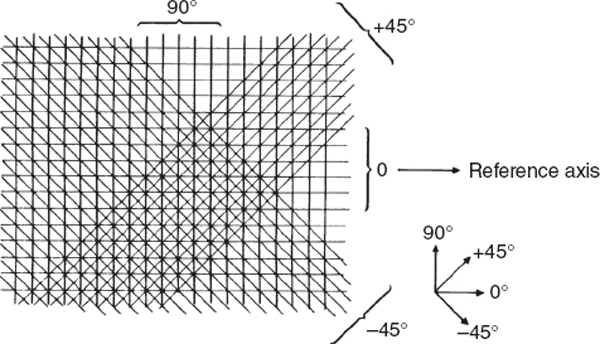
FIGURE 11-4 Warp clock to indicate ply orientation.
Symmetry and Balance
Composite laminate structures must be symmetrical and balanced to reduce stresses and to avoid distortion of the laminate. A lay-up needs to be symmetrical or the lay-up will either curve or twist during the curing process. Symmetry of lay-up means that for each layer above the midplane of the laminate there must exist an identical layer (same thickness, material properties, and angular orientation) below the midplane. To achieve balance, for every layer centered at some positive angle there must exist an identical layer oriented at a negative angle with the same thickness and material properties. If the laminate contains only 0° and/or 90° layers it satisfies the requirements for balance. Figure 11-5 shows a symmetrical laminate.

FIGURE 11-5 Symmetrical lay-up.
Types of Fiber
The most common used dry fibers for the aerospace industry are: fiberglass, carbon fiber, and aramid (Kevlar). All materials should be stored on a roll off the ground in a dry environment at room temperature. Figure 11-6 shows a storage rack with dry reinforcements. The dry fabric will be impregnated with a resin just before the repair work starts. This process is often called wet lay-up. The main advantage of using the wet lay-up process is that the fiber and resin can be stored for a long time at room temperature. The composite can be cured at room temperature or an elevated temperature cure can be used to speed up the curing process and increase the strength. Disadvantages: process is messy and properties are less than pre-preg material properties.
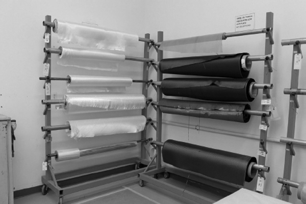
FIGURE 11-6 Dry fiber materials. See also color insert.
Fiberglass
Fiberglass is often used for secondary structures on aircraft such as fairings, radomes, wing tips, helicopter rotor blades, and interior components. The properties of fiberglass are less than carbon fiber but the cost of fiberglass is substantially lower than carbon fiber and therefore fiberglass is an economical substitution if high strength and stiffness are not required. Fiber glass is available as continuous rovings, yarn for fabrics or braiding, mats, and chopped strand. The most common form of fiberglass is “E” glass. Electrical glass or E-glass is identified as such for electrical applications, but is used for many other applications as well. S-glass and S2-glass identify structural fiberglass that have a higher strength than E-glass. Advantages of fiberglass are: lower cost than other composite materials, chemical or galvanic corrosion resistance, and electrical properties (fiberglass does not conduct electricity). Fiberglass is distinguished by its white color as seen in Fig. 11-7, but it is also available in different colors.

FIGURE 11-7 Dry fiberglass fabric material. See also color insert.
Kevlar®
Kevlar® is DuPont’s trademark name for aramid fibers. Aramid fiber is used as a fabric material for aerospace applications. Aramid is an organic fiber that is 43 percent lighter than and twice as strong in tension as fiberglass. Aramid fibers are generally weak in compression and are difficult to cut due to fuzzing. The main disadvantage is that the aramid fibers are hygroscopic and can absorb 8 percent of their weight of water. Aramid is recognized by its yellow color as shown in Fig. 11-8. Kevlar® 49 is used in reinforced plastics for secondary structures on some aircraft.
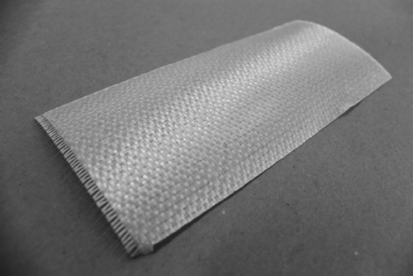
FIGURE 11-8 Aramid (Kevlar) fabric material. See also color insert.
Carbon/Graphite
Carbon fibers, commonly called graphite, are made from organic materials. Graphite fibers have a high potential for causing galvanic corrosion when used with metallic fasteners and structures. Composites made from carbon fiber are five times stronger than grade 1020 steel for structural parts, yet are still five times lighter. In comparison to 6061 aluminum, carbon fiber composites are seven times stronger and two times stiffer, yet 1.5 times lighter. Carbon fiber composites have fatigue properties superior to all known metals, and, when coupled with the proper resins, carbon fiber composites are one of the most corrosion-resistant materials available. Carbon fiber is used for structural aircraft applications such as floor beams, stabilizers, flight controls, and primary fuselage and wing structure. Advantages are high strength, low fatigue, and corrosion resistance. Disadvantages are lower conductivity than aluminum. Carbon fibers are available in continuous filament-spooled fiber, milled fiber, chopped fiber, woven fabrics, felts, veils, and chopped fiber mattes. The size of the carbon fiber tow bundle can range from 1000 filaments (1K) to more than 200K. Generally, aerospace carbon fibers are available in bundles of 3K, 6K, 12K, and 24K filaments. Carbon fiber is recognized by its black color as shown in Fig. 11-9.
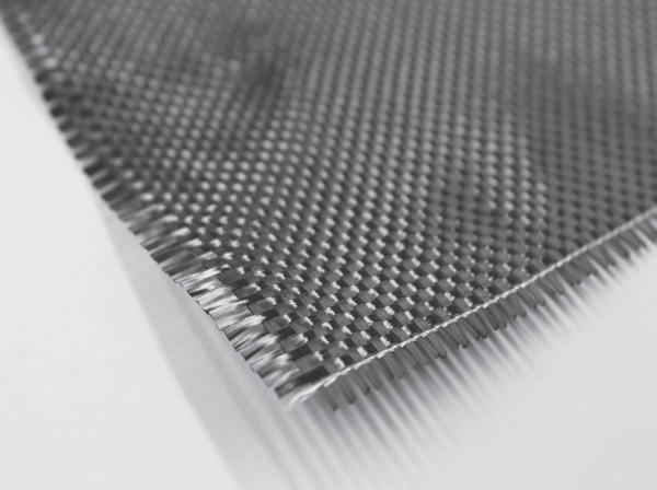
FIGURE 11-9 Carbon fiber material. See also color insert.
Boron Fibers
Boron fibers are very stiff and have a high tensile and compressive strength. The fibers have a relative large diameter and do not flex well and are therefore only available as a pre-preg tape product. An epoxy matrix is often used with the boron fiber. Boron fibers are often used to repair cracked aluminum aircraft skins because the thermal expansion of boron is close to aluminum and there is no galvanic corrosion potential. The boron fiber is difficult to use if the parent material surface has a contoured shape. The boron fibers are very expensive and can be hazardous for personnel. Boron fibers are used primarily in military aviation applications.
Ceramic Fibers
Ceramic fibers are used for high-temperature applications such as turbine blades in the turbine section of a gas turbine engine. The ceramic fibers can be used to temperatures up to 2200°F.
Lightning Protection Fibers
High-energy lightning strikes can cause substantial damage to composite aircraft structures. An aircraft made from aluminum alloy is quite conductive and is able to dissipate the high currents resulting from a lightning strike. However, aircraft made from composite materials need additional protection because, for instance, carbon fibers are 1000 times more resistive than aluminum to current flow, and epoxy resin is 1 million times more resistive. Many different types of conductive materials are used to protect composite aircraft ranging from nickel-coated graphite cloth to metal meshes, as shown in Fig. 11-10, to aluminized fiberglass to conductive paints. Aluminum mesh is often used with fiberglass and Kevlar materials but copper mesh is required for carbon fiber material because aluminum will corrode quickly if used on top of carbon fiber. If a composite aircraft gets damaged, in addition to a normal structural repair, the technician must also recreate the electrical conductivity designed into such a part.

FIGURE 11-10 Aluminum mesh for lightning strike protection. See also color insert.
Fiber Forms
All product forms generally begin with spooled unidirectional raw fibers packaged as continuous strands. An individual fiber is called a filament. The word strand is also used to identify an individual glass fiber. Bundles of filaments are identified as tows, yarns or rovings. Roving and tows are used to identify groups of long continuous fibers. A roving or tow is a single grouping of filament or fiber ends, such as 20-end or 60-end glass rovings. All filaments are in the same direction and they are not twisted. Carbon tows are usually identified as 3K, 6K, or 12K tows. K means 1000 filaments. When individual fiberglass filaments are twisted they are called yarns. Carbon fiber and Kevlar fibers are not twisted. Most fibers are available as dry fiber that needs to be impregnated with a resin before use or pre-preg materials where the resin is already applied to the fiber. Figure 11-11 shows the different forms of fiber material available. The most common forms of fiber products for the aerospace industry are unidirectional products (also called tape) and bidirectional woven products (also called fabric).
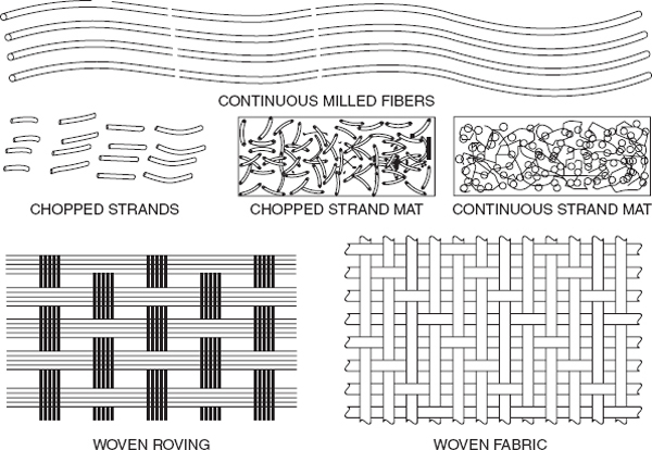
FIGURE 11-11 Dry fiber materials.
Unidirectional (Tape)
High-strength structural applications are often manufactured from unidirectional material. In unidirectional material, all the fibers are running in the same direction and the material has only strength properties in the fiber direction. Several layers of unidirectional material are required to create a laminate that has uniform strength in all directions. Unidirectional materials are typically available as pre-preg materials. Figure 11-12 shows a unidirectional carbon fiber material. Figure 11-13 shows unidirectional and bidirectional fibers.

FIGURE 11-12 Unidirectional material (carbon fiber). See also color insert.

FIGURE 11-13 Bidirectional (fabric) and unidirectional (tape) properties.
Bidirectional (Fabric)
Bidirectional materials, often called fabric, are woven materials that use tows of composite material. A weaving process similar to what is used to manufacture textile products is used to make the fabric material. Fabric constructions offer more flexibility for lay-up of complex shapes than straight unidirectional tapes offer. For aerospace structures, tightly woven fabrics are usually the choice to save weight, minimizing resin void size, and maintaining fiber orientation during the fabrication process. The more common fabrics are plain, basket, or satin weaves. The plain weave, which is most highly interlaced, is therefore the tightest of the basic fabric designs and most resistant to in-plane shear movement. The plain weave construction results from each fiber alternating over and then under each intersecting tow. Basket weave, a variation of plain weave, has warp and fill yarns that are paired: two up and two down. With the common satin weaves, such as 5 harness or 8 harness, the fiber bundles traverse both in warp and fill directions changing over/under position less frequently. Satin weaves have less crimp and are easier to distort than a plain weave and are used for more complex shapes. Fabrics are widely available as dry fiber or pre-preg materials. Figure 11-14 shows fabric weave styles.

FIGURE 11-14 Basic weave styles for composite bidirectional products.
Nonwoven (Knitted or Stitched)
Multiaxial fabrics are used more frequently for the manufacture of composite components. These fabrics consist of one or more layers of continuous fibers held in place by a secondary, nonstructural stitching thread. The stitching process allows a variety of fiber orientations, beyond the simple 0/90° of woven fabrics, to be combined into one fabric. Figure 11-15 shows a stitched nonwoven fabric.

FIGURE 11-15 Stitched multiaxial fabric.
Matrix Materials
The resin is often referred to as the matrix of a composite. The role of the matrix is to support the fibers and bond them together in the composite material. It transfers any applied loads to the fibers and keeps the fibers in their position and chosen orientation. The matrix also gives the composite environmental resistance and determines the maximum service temperature of the finished component. The two main classes of resins are: thermoset and thermoplastic.
Thermosetting Resins
Thermoset materials take a permanent set or shape when cured. Cure temperatures range from room temperature to 350°F for polyesters, vinyl esters, epoxies, and cyanate esters, around 450°F for bismaleimide (BMI) materials, and close to 700°F for polyimides. Cure pressures are usually less than 100 pounds per square inch (psi). The most common type of thermoset resin used for aircraft construction is epoxy because of its excellent mechanical properties, extended service temperature range, and ease of part manufacture. The advantages of epoxies are high strength and modulus, low levels of volatiles, excellent adhesion, low shrinkage, good chemical resistance, and ease of processing. Their major disadvantages are brittleness and the reduction of properties in the presence of moisture. Bismaleimide (BMI) resins are used when a higher service temperature is required. BMIs have epoxy-like processing characteristics yet have a higher temperature use limit. BMIs require higher cure temperatures than used for epoxies, typically 375 to 450°F. BMIs are used for aero engines and high-temperature components. Phenol-formaldehyde resins were first produced commercially in the early 1900s for use in the commercial market. Urea-formaldehyde and melamine-formaldehyde appeared in the 1920s to 1930s as a less expensive alternative for lower temperature use. Phenolic resins are used for interior components because of their low smoke and flammability characteristics. Polyimide resins excel in high temperature environments where their thermal resistance, oxidative stability, low coefficient of thermal expansion, and solvent resistance benefit the design. Their primary uses are circuit boards and hot engine and aerospace structures. A polyimide may be either a thermoset resin or a thermoplastic. Polyimides require high cure temperatures, usually in excess of 550°F [~290°C]. Consequently, normal epoxy composite bagging materials are not usable, and steel tooling becomes a necessity. Polyimide bagging and release films, such as Kapton and Upilex, replace the lower-cost nylon bagging and polytetrafluoroethylene (PTFE) release films common to epoxy composite processing. Fiberglass fabrics must be used for bleeder and breather materials instead of polyester mat materials.
Curing Stages of Thermoset Resins. Thermosetting resins use a chemical reaction to cure. There are three types of curing stages which are called A, B, and C stage.
A stage. The components of the resin (base material and hardener) have been mixed but the chemical reaction has not started. The resin is in the A stage during a wet lay-up procedure.
B stage. The components of the resin have been mixed and the chemical reaction has started. The material has thickened and is tacky. Pre-preg materials are in the B stage. To prevent further curing the resin is placed in a freezer at 0°F. In the frozen state the resin of the pre-preg material will stay in the B stage. The curing will start when the material is removed from the freezer and heated up again.
C stage. The resin is fully cured. Some resin systems cure at room temperature and others need an elevated temperature cure cycle to fully cure.
Thermoplastic Resins
Thermoplastic materials are non-curing systems that can be reshaped or reformed after the part has been processed or consolidated. Reshaping is accomplished by reheating the part until the material softens and applying pressure to produce a newly molded shape. Thermoplastics are consolidated at temperatures up to 800°F and pressures up to 200 psi. Polyetheretherketone (PEEK) is an often used resin system for the aerospace industry to make structural parts. Semicrystalline thermoplastics possess properties of inherent flame resistance, superior toughness, good mechanical properties at elevated temperatures and after impact, and low moisture absorption. They are used in secondary and primary aircraft structures. Combined with reinforcing fibers, they are available in injection molding compounds, compression-moldable random sheets, unidirectional tapes, towpregs, and woven pre-pregs. Fibers impregnated include carbon, nickel-coated carbon, aramid, glass, quartz, and others. Amorphous thermoplastics are available in several physical forms, including films, filaments, and powders. Combined with reinforcing fibers, they are also available in injection molding compounds, compressive moldable random sheets, unidirectional tapes, woven pre-pregs, etc. The fibers used are primarily carbon, aramid, and glass. The specific advantages of amorphous thermoplastics depend upon the polymer. Typically, the resins are noted for their processing ease and speed, high temperature capability, good mechanical properties, excellent toughness and impact strength, and chemical stability. The stability results in unlimited shelf life, eliminating the cold storage requirements of thermoset pre-pregs.
Preimpregnated Products (Pre-pregs). Pre-preg material consists of a combination of a matrix and fiber reinforcement. It is available in unidirectional form (one direction of reinforcement) and fabric form (several directions of reinforcement). All the major families of matrix resins can be used to impregnate various fiber forms. The resin is then no longer in a low-viscosity stage, but has been advanced to a B-stage level of cure for better handling characteristics. The following products are available in pre-preg form: unidirectional tapes, woven fabrics, continuous strand rovings, and chopped mat. Pre-preg materials must be stored in a freezer at a temperature below 0°F to retard the curing process. Pre-preg materials are cured with an elevated temperature. Many pre-preg materials used in aerospace are impregnated with an epoxy resin and they are cured at either 250 or 350°F. Figure 11-16 shows pre-preg materials.
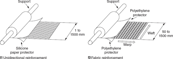
FIGURE 11-16 Pre-preg materials.
Adhesives
Epoxy-based adhesives are the most used materials for bonding or repair of composite structures. Epoxy adhesives impart high-strength bonds and long-term durability over a wide range of temperatures and environments. Some epoxy adhesive systems cure at room temperature, while others require elevated temperatures to achieve optimum bonding characteristics. Adhesives are available as film adhesives, paste adhesives, and foaming adhesives.
Film Adhesives
Structural adhesives for aerospace applications are generally supplied as thin films supported on a release paper and stored under refrigerated conditions (-18°C, or 0°F). Film materials are frequently supported by fibers that serve to improve handling of the films prior to cure, control adhesive flow during bonding, and assist in bondline thickness control. Adhesive films have a separator film or backing paper which is applied to keep the material from sticking to itself. Film adhesives are tacky at room temperature and above. When applying film adhesives, it is important to prevent or eliminate entrapped air pockets between the aircraft surface and adhesive film by pricking bubbles or “porcupine” rolling over the adhesive prior to application. Figure 11-17 shows the application of film adhesives.

FIGURE 11-17 The use of film adhesives for aircraft repair.
Paste Adhesives
Paste adhesives are used in the repair of composite parts as filler materials, for bonding repair core sections in place, and for bonding repair patches. Paste adhesives are two-component systems requiring careful weighing and thorough mixing to ensure strength is not compromised. Compared to film adhesives, paste adhesives have the advantage of lower-temperature cure cycles and are easier to store and ship. However, they have the disadvantage of lower strength, poor bond-line thickness control, and higher overall repair weight when compared to film adhesives. Application of paste adhesives can be accomplished by brush, by spreading with a grooved tool, or by extrusion from cartridges or sealed containers using compressed air.
Foaming Adhesives
Foaming adhesives consist of a thin unsupported epoxy film containing a blowing agent. During the rise to cure temperature, an inert gas is liberated causing an expansion or foaming action in the film. The expansion must be performed under positive pressure to prevent over-expansion and reduced strength. Following expansion, the adhesive is cured into strong highly structured foam. It is used as a lightweight splice material for splicing honeycomb core repair sections. Like film adhesives, foaming adhesives have the disadvantage of requiring a high-temperature cure cycle and must be shipped and stored at or below 0°F. They are sensitive to moisture, temperature, and contamination in the uncured state and must be handled and stored properly to prevent degradation. Figure 11-18 shows how foaming adhesives are used for the splicing and repair of honeycomb structures.
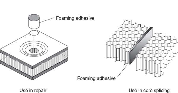
FIGURE 11-18 The application of foaming adhesives.
DESCRIPTION OF SANDWICH STRUCTURES
A sandwich construction is a structural panel concept that consists in its simplest form of two relatively thin, parallel face sheets bonded to and separated by a relatively thick, lightweight core. The core supports the face sheets against buckling and resists out-of-plane shear loads. The core must have high shear strength and compression stiffness. Honeycomb’s beneficial strength-to-weight and stiffness-to-weight ratios compared to other materials and configurations are unmatched. Figure 11-19 shows a basic honeycomb sandwich construction.

FIGURE 11-19 Honeycomb sandwich construction.
Properties
Sandwich construction has high bending stiffness at minimal weight in comparison to aluminum and composite laminate construction. Most honeycomb sandwich structures are anisotropic; that is, properties are directional. As shown in Fig. 11-20, sandwich construction, especially honeycomb core construction, is structurally efficient, particularly in stiffness critical applications. Doubling the thickness of the core increases the stiffness over 7 times with only a 3% weight gain, while quadrupling the core thickness increases stiffness over 37 times with only a 6% weight gain.

FIGURE 11-20 The stiffening effect of honeycomb sandwich structure.
Facing Materials
Most honeycomb structures used in aircraft construction use aluminum, fiberglass, Kevlar, or carbon fiber face sheets. Carbon fiber face sheets cannot be used with aluminum honeycomb core material because they will cause the aluminum to corrode. Titanium and steel are used for specialty applications in high-temperature constructions. The face sheets of many components such as spoilers and flight controls are very thin, sometimes only 3 or 4 plies. Figure 11-21 shows a honeycomb structure with aluminum face sheets and aluminum honeycomb core.
FIGURE 11-21 Aluminum honeycomb sandwich structure. See also color insert.
Core Materials
The most common core materials used in aerospace are aluminum and Nomex (Fig. 11-22). Nomex is paper that is impregnated with a phenolic resin. Aluminum core cannot be used with carbon fiber face sheets because the aluminum will corrode.

FIGURE 11-22 Honeycomb sandwich core materials. See also color insert.
Honeycomb
Honeycomb core cells for aerospace applications are usually hexagonal. The cells are made by bonding stacked sheets at special locations. The stacked sheets are expanded to form hexagons. The direction parallel to the sheets is called ribbon direction. Honeycomb material is available in several different kinds of materials. Metallic and nonmetallic materials are used in combination with carbon fiber, fiber glass, and Kevlar face sheets. Nonmetallic materials used are: fiberglass-reinforced honeycombs, Nomex, and Korex.
Honeycomb cell structures are available in several different styles depending on the application. The hexagonal structure is the most common type and used when the part is relatively flat. Flexicore is used when the honeycomb core material needs to be formed in a tighter contour than is possible with hexagonal honeycomb. The flexible core is used for parts that have a compound contour. Figure 11-23 shows the different styles of honeycomb core cells. Honeycomb core is available with different cell sizes. Small sizes provide better support for sandwich face sheets. Honeycomb is also available in different densities. Higher density core is stronger and stiffer than lower density core.

FIGURE 11-23 Honeycomb core cell configurations.
Foam
Foam cores are used on homebuilts and general aviation aircraft to give strength and shape to wing tips, flight controls, fuselage sections, wings, and wing ribs. Foam cores are not commonly used on commercial-type aircraft. Foam cores include a wide variety of liquid plastic materials that are filled with chemically released or mechanically mixed gas bubbles to produce rigid forms. Several types of foam core are available including polyvinyl chloride (cross-linked and uncross-linked), polyurethane, ebonite, polyimide, polymethacrylimide, and styrofoam. Carbon foam, a notable core material used for medium- to high-temperature applications, is made from coal. The mechanical properties of foam cores vary in an approximately linear fashion with material density. Foams tend to have lower mechanical properties than honeycomb, for a given weight.
Balsa Wood
Balsa is a natural wood product with elongated closed cells; it is available in a variety of grades that correlate to the structural, cosmetic, and physical characteristics. The density of balsa is less than one-half of the density of conventional wood products. However, balsa has a considerably higher density than the other types of structural cores. Modern aircraft floor panels, galley structures, and wardrobes may be fabricated from sandwich panels of balsa core faced with fiberglass or aluminum.
Description of Laminated Structures
Honeycomb sandwich might be the most efficient structural design for composite aircraft structures, but it also has some disadvantages: low impact damage resistance, water intrusion, and difficult to repair especially with fasteners. For these reasons new aircraft designs such as the Boeing 787 and Airbus 350 use a laminate type of composite structure for the wing and fuselage primary structure instead of a honeycomb structure. The reasons for this are that laminate structures are more damage tolerant, easier to repair, and easier to manufacture with automated manufacturing techniques. A laminate design consists of a laminate face sheet reinforced by external stringers and reinforcements as shown in Fig. 11-24. This design is similar to a semi-monoque design used for aluminum aircraft and sometimes called black aluminum. However, often the reinforcements and stringers are co-cured with the face sheet which eliminates secondary bonding processes or the use of fasteners.

FIGURE 11-24 Composite laminate structure with stringers.
Manufacturing and In-Service Damage
Damage from a great many causes, such as scratching, gouging, impact, abrasion, erosion, local chemical attack or overheating, may affect only a few surface plies over a large area or a depth of many plies in a smaller area. Failure to use protective devices, such as padded fixtures and sacrificial plies, may cause additional damage. Inadvertent or accidental impact may occur during the handling of parts during maintenance. The types of damage range from small surface scratches to more severe defects that would include punctures. Once damage is identified, the extent of damage must be determined and then it can be classified to determine the disposition of the defective part. Improper damage removal and repair techniques can impart greater damage than originally sustained to the composite material.
Manufacturing Defects
Manufacturing damage includes anomalies such as porosity, microcracking, and delaminations resulting from processing discrepancies and also such items as inadvertent edge cuts, surface gouges and scratches, damaged fastener holes, and impact damage. Examples of flaws occurring in manufacturing include a contaminated bondline surface or inclusions such as pre-preg backing paper or separation film that is inadvertently left between plies during lay-up. The inadvertent (non-process) damage can occur in detail parts or components during assembly or transport or during operation. A part is called resin rich if too much resin is used; for non-structural applications this is not necessarily bad but it will add weight. A part is called resin starved if too much resin is bled off during the curing process or if not enough resin is applied during the wet lay-up process. Resin-starved areas are indicated by fibers that show to the surface. The 60:40 fiber-to-resin ratio is considered optimum. Damage can occur at several scales within the composite material and structural configuration. This ranges from damage in the matrix and fiber to broken elements and failure of bonded or bolted attachments. The extent of damage controls repeated load life and residual strength and is, therefore, critical to damage tolerance.
Fiber Breakage. This defect can be critical because structures are typically designed to be fiber dominant (i.e., fibers carry most of the loads). Fortunately, fiber failure is typically limited to a zone near the point of impact, and is constrained by the impact object size and energy. Only a few of the service-related events listed in the previous section could lead to large areas of fiber damage.
Matrix Imperfections. These usually occur on the matrix-fiber interface, or in the matrix parallel to the fibers. These imperfections can slightly reduce some of the material properties but will seldom be critical to the structure, unless the matrix degradation is widespread. Accumulation of matrix cracks can cause the degradation of matrix-dominated properties. For laminates designed to transmit loads with their fibers (fiber dominant), only a slight reduction of properties is observed when the matrix is severely damaged. Matrix cracks, a.k.a. micro-cracks, can significantly reduce properties dependent on the resin or the fiber/resin interface, such as interlaminar shear and compression strength. For high-temperature resins, micro-cracking can have a very negative effect on properties. Matrix imperfections may develop into delaminations, which are a more critical type of damage.
Delamination and Debonds. Delaminations form on the interface between the layers in the laminate. Delaminations may form from matrix cracks that grow into the interlaminar layer or from low-energy impact. Debonds can also form from production non-adhesion along the bondline between two elements and initiate delamination in adjacent laminate layers. Under certain conditions, delaminations or debonds can grow when subjected to repeated loading and can cause catastrophic failure when the laminate is loaded in compression.
Combinations of Damages. In general, impact events cause combinations of damages. High-energy impacts by large objects (i.e., turbine blades) may lead to broken elements and failed attachments. The resulting damage may include significant fiber failure, matrix cracking, delamination, broken fasteners, and debonded elements. Damage caused by low-energy impact is more contained, but may also include a combination of broken fibers, matrix cracks, and multiple delaminations.
Flawed Fastener Holes. Improper hole drilling, poor fastener installation, and missing fasteners may occur in manufacturing. Hole elongation can occur due to repeated load cycling in service. Due to the low bearing loads of composite structures flawed fastener holes need to be repaired to design loads.
In-Service Defects
Many honeycomb structures such as wing spoiler, fairings, flight controls, and landing gear doors have thin face sheets which have experienced durability problems that could be grouped into three categories: low resistance to impact, liquid ingression, and erosion. These structures have adequate stiffness and strength, but low resistance to a service environment where parts are crawled over, tools dropped, and where technicians are often unaware of the fragility of thin-skinned sandwich parts. Damages to these components, such as core crush, impact damages, and disbonds, are quite often easily detected with a visual inspection due to their thin face sheets. Damages are sometimes allowed to go unchecked, often resulting in growth of the damage due to liquid ingression into the core.
The repair of parts due to liquid ingression can vary depending upon the liquid, of which water and Skydrol (hydraulic fluid) are the two most common. Water tends to create additional damage in repaired parts when cured unless all moisture is removed from the part. Most repair material systems cure at temperatures above the boiling point of water, which can cause a disbond at the skin-to-core interface wherever trapped water resides. For this reason, core drying cycles are typically included prior to performing any repair. Some operators will take the extra step of placing a damaged but unrepaired part in the autoclave to dry so as to preclude any additional damage from occurring during the cure of the repair. Skydrol presents a different problem. Once the core of a sandwich part is saturated, complete removal of Skydrol is almost impossible. The part continues to weep the liquid even in cure such that bondlines can become contaminated and full bonding does not occur. Removal of contaminated core and adhesive as part of the repair is highly recommended.
Erosion capabilities of composite materials have been known to be less than that of aluminum and, as a result, their application in leading edge surfaces has been generally avoided. However, composites have been used in areas of highly complex geometry, but generally with an erosion coating. The durability and maintainability of some erosion coatings are less than ideal. Another problem, not as obvious as the first, is that edges of doors or panels can erode if they are exposed to the air stream. This erosion can be attributed to improper design or installation/fit-up. On the other hand, metal structures in contact or in the vicinity of these composite parts may show corrosion damage due to: inappropriate choice of aluminum alloy, damaged corrosion sealant of metal parts during assembly or at splices or insufficient sealant, and/or lack of glass fabric isolation plies at the interfaces of spars, ribs, and fittings.
There has been a concern with UV radiation affecting composite structures. Composite structures need to be protected by a top coating to prevent the effects of UV light. Special UV primers and paints have been developed to protect composite materials. Many fiberglass and Kevlar parts have a fine aluminum mesh for lightning protection. This aluminum mesh often corrodes around the bolt or screw holes. The corrosion affects the electrical bonding of the panel, and the aluminum mesh will need to be removed and new mesh installed to restore the electrical bonding of the panel. Figure 11-25 shows a panel where the aluminum mesh around the fastener holes is severely corroded.

FIGURE 11-25 Corrosion of aluminum lightning strike mesh on composite panel. See also color insert.
Nondestructive Inspection of Composites
Damage to composite components is not always visible to the naked eye and the extent of damage is best determined for structural components by suitable nondestructive test (NDT) methods also called nondestructive inspection (NDI). NDI methods range from simple visual inspections to very sophisticated automated systems with extensive data handling capabilities. It should be noted that composites are generally more difficult to inspect than metals because laminated structures contain multiple ply orientations with numerous ply drop-offs. In addition, it is important that technicians conducting NDI be trained and certified in the method they are using. Table 11-1 shows what type of defects can be detected with what type of NDI methods.

Visual Inspection
Visual inspections are often used to inspect metallic and composite aircraft. Large areas can be inspected quickly and if damage is suspected more detailed inspection methods can be used to verify the damage. Flashlights, magnifying glasses, mirrors, and borescopes are employed as aids in the visual inspection of composites. These aids are used to magnify defects which otherwise might not be seen easily and to allow visual inspection of areas that are not readily accessible. Shining a flash light under an angle is a great aid to find damage. Resin starvation, resin richness, wrinkles, ply bridging, discoloration (due to overheating, lightning strike, etc.), impact damage by any cause, foreign matter, and blisters are some of the discrepancies readily discernible by a visual inspection. Visual inspection cannot find internal flaws in the composite, such as delaminations, disbonds, and matrix crazing. More sophisticated NDT is needed to detect these types of flaws.
Audible Sonic Testing (Coin Tapping)
Coin tapping, also called tap testing, with a coin or small hammer is often used to find subsurface damage to thin honeycomb or laminate structures. The method consists of lightly tapping the surface of the part with a coin or other suitable object. The acoustic response of the damaged area is compared with that of a known good area. An acoustically flat or dull response is considered unacceptable. A dull sound is a good indication that some delamination or disbond exists, although a clear, sharp tapping sound does not necessarily ensure the absence of damage, especially in thick panels. The acoustic response of a good part can also vary dramatically with changes in geometry; therefore, the geometry and interior construction of the part must be known before performing the tap test. If results are questionable, the technician can compare the results to a tap test of other like parts which are known to be good or use another inspection method. The automated tap test uses a solenoid instead of a hammer and this type of device will give a more consistent reading than the manual tap test. Figure 11-26 shows a technician performing a tap test of a nose radome.
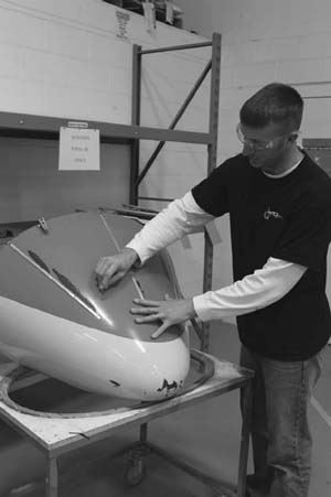
FIGURE 11-26 Coin (tap) testing of nose radome.
Ultrasonic Inspection
Ultrasonic inspection has proven to be a very useful tool for the detection of internal delaminations, voids, or inconsistencies in composite components not otherwise discernible using visual or tap methodology. There are many ultrasonic techniques; however, each technique uses sound wave energy with a frequency above the audible range. A high-frequency (usually several megahertz) sound wave is introduced into the part and may be directed to travel normal to the part surface or along the surface of the part, or at some predefined angle to the part surface. Different directions are used as the flow may not be visible only from one direction. The introduced sound is then monitored as it travels its assigned route through the part for any significant change. Ultrasonic sound waves have properties similar to light waves. When an ultrasonic wave strikes an interrupting object, the wave or energy is either absorbed or reflected back to the surface. The disrupted or diminished sonic energy is then picked up by a receiving transducer and converted into a display on the test equipment. The display allows the operator to comparatively evaluate the discrepant indications against those areas known to be good. To facilitate the comparison, reference standards are established and utilized to calibrate the ultrasonic equipment. The most common types of ultrasonic test equipment are through transmission, pulse echo, phase array, and bond tester. Figure 11-27 shows basic through transmission and pulse echo inspection techniques, and Fig. 11-28 shows equipment that could be used for phase array and pulse echo ultrasonic inspections. Figure 11-29 shows a large through transmission set-up to test large surfaces.

FIGURE 11-27 Through transmission and pulse echo ultrasonics.
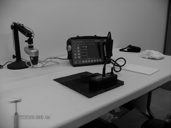
FIGURE 11-28 Phase array and pulse echo inspection equipment. See also color insert.

FIGURE 11-29 Through transmission ultrasonic equipment.
Radiography
Radiography, or X-ray, as it is often referred to, is a very useful NDI method in that it essentially allows a view into the interior of the part. This inspection method is accomplished by passing X-rays through the part or assembly being tested while recording the absorption of the rays onto a film sensitive to X-rays. Low-energy X-ray, gamma ray, or neutron emissions penetrate the test article. Variations in material thickness or density and the presence of flaws affect the intensity of the transmitted radiation. Voids and other discontinuities attenuate the radiation to different degrees and are revealed as contrasting light and dark areas (shadows) on the recorded image. Defects less dense than surrounding material (such as voids in a composite laminate) absorb less radiation and are shown on X-ray film as darker areas as compared to nearby images. Defects more dense than surrounding areas absorb more radiation (such as water in honeycomb sandwich assemblies) and are shown as lighter areas on X-ray film when compared to nearby images.
Thermography
Thermography comprises all methods in which heat-sensing devices are used to measure temperature variations for parts under inspection. Most common sources of heat are heat lamps or heater blankets. The basic principle of thermal inspection consists of measuring or mapping of surface temperatures when heat flows from, to, or through a test object. All thermographic techniques rely on differentials in thermal conductivity between normal, defect-free areas and those having a defect. Normally, a heat source is used to elevate the temperature of the article being examined while observing the surface heating effects. Because defect-free areas conduct heat more efficiently than areas with defects, the amount of heat that is either absorbed or reflected indicates the quality of the bond. The type of defects that affect the thermal properties include disbonds, cracks, impact damage, panel thinning, and water ingress into composite materials and honeycomb core. Thermal methods are most effective for thin laminates or for defects near the surface.
Damage Assessment
After the damage to the aircraft has been inspected the damage needs to be assessed and a decision must be made about if and how to repair the damaged structure, the nature of the repair (permanent or temporary), and the needed inspection after the repair and during the residual life of the repaired structure. This decision depends upon where the damage is detected, the accuracy of damage characterization, the means available for determining the severity of the damage, and designing and performing an adequate repair.
Damage Categories
Permanent repair. A permanent repair restores the stiffness of the original structure, withstands static strength at the expected environments up to ultimate load, ensures durability for the remaining life of the component, satisfies original part damage tolerance requirements, and restores functionality of aircraft systems. Other criteria applicable in repair situations are to minimize aerodynamic contour changes, minimize weight penalty, minimize load path changes, and be compatible with aircraft operations schedule.
Interim repairs. Repair design criteria for temporary or interim repairs can be less demanding, but may approach permanent repairs if the temporary repair is to be on the airplane for a considerable time. Most users of aircraft and original equipment manufacturer (OEMs) prefer permanent repairs, if at all possible, as the temporary repairs may damage parent structure, necessitating a more extensive permanent repair or part scrapping. All temporary repairs have to be approved before the aircraft can be restored to operational status.
Cosmetic repair. Cosmetic repairs do not affect the structural integrity of the component or aircraft. A cosmetic repair is carried out to protect and decorate the surface. This will not involve the use of reinforcing materials.
Composite Repairs
The damage to an aircraft structure needs to be repaired or the part must be replaced after the damage has been inspected and evaluated. Primary structure on large transport aircraft cannot be replaced easily or not at all and the damage must be repaired on the aircraft using portable curing equipment. Smaller secondary structure parts such as flight controls, fairings, and interior parts can be removed from the aircraft and be repaired in the composite shop where ovens and autoclaves are available to restore the structural integrity of the part.
Hand Tools
The technician involved in composite repair work will have to use hand tools such as utility knives and pizza cutters to cut dry fabrics, vacuum bag materials, and pre-pregs. Knives with quick-change, retractable blades are preferred because blades must be changed often and they enhance safety. Scissors are used to cut dry fabrics. Materials made from Kevlar are more difficult to cut than fiber glass or carbon and tools will wear more quickly. Special scissors for Kevlar are available. Figure 11-30 shows a series of hand tools. Electric-driven cutters are also available for thicker fabrics and higher production.

FIGURE 11-30 Cutting tools.
Air Tools
Air-driven power tools such as drill motors, routers, grinders, and orbital sanders are used for composite repair. Electric motors are not recommended because carbon is a conductive material that can cause an electrical short circuit. If electric tools are used they need to be of the totally enclosed type. The technician should wear a respirator, protective clothing, and gloves when drilling, grinding, or sanding composite materials. Figure 11-31 shows an orbital sander.

FIGURE 11-31 The use of an orbital sander for repair work. See also color insert.
Caul Plate
Caul plates are mostly made from aluminum or steel and are used to support the part during the cure cycle in an oven or autoclave. The composite shop will have a large assortment of caul plates for various jobs. A thin aluminum caul plate is often used when a repair is made on the aircraft using a heat bonder and vacuum pressure. The caul plate is placed in the vacuum bag on top of the bleeder ply separated by a solid parting film (release material). The heater blanket will be placed on top of the caul plate. The caul plate will provide a more uniform heated area and it will leave a smoother finish of the composite laminate. Either release film or mold release is used to prevent the caul plate from adhering to the part.
Vacuum Bag Materials
The vacuum bag process is the most common way to apply pressure to a composite repair that is performed on the aircraft. This process requires several types of processing materials to be used. These materials do not become part of the repair and will be discarded after the repair process. Release films, release agents, fiberglass bleeders, random matt polyester breathers, sealant tape, and vacuum bag film are commonly used. Vacuum bag materials should be stored in a dry and clean room on a rack as shown in Fig. 11-32.
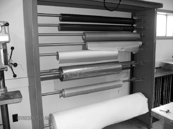
FIGURE 11-32 Vacuum bag processing materials. See also color insert.
Release Agents
Release agents, also called mold release, are used on caul plates, molds, and tools to ensure that the part will release from the caul plate, mold, or tool after the curing process. Due to environmental regulation water-based agents have been introduced that are easier to use. Release agents can contaminate the repair process and could cause poor bonding, and for this reason the application of release agents should be carried out away from the repair area.
Bleeder Ply
Bleeder plies are used in a composite repair with a vacuum bag to bleed off excess resin and remove air and volatiles that are trapped in the repair area. Bleeders are always used with wet lay-up repairs and sometimes with pre-preg repairs depending on the resin content of the pre-preg. Net resin pre-pregs do not require a bleeder and a bleeder should not be used because this will cause a resin-starved (dry) part or repair. The number of bleeder plies required for the repair will determine how much resin is bled off. Typical materials for a bleeder are either fiberglass or polyester.
Peel Ply
Peel plies are made from polyester or nylon and are used to create a ready surface for bonding purposes. A peel ply will be placed on the area of the lay-up that needs to be secondary bonded to another part. Just before the part will be bonded to the structure the peel ply will be removed. The removal of the peel ply creates a rough surface that is desirable for the bonding process. Uncoated and coated peel plies are available and for bonding purposes the uncoated peel plies are preferred. Some silicon-coated peel plies can leave an undesirable contamination on the surface which will actually decrease the bonding strength. The preferred peel ply material is polyester which has been heat-set to eliminate shrinkage. The uncoated peel plies can be difficult to remove after the curing process.
Sealant Tape
Heat-resistant sealant tape, also called sticky tape, is used to seal the vacuum bag to the part, or tool. The type of sealant tape to be used depends on the cure temperature of the part. Some sealant tapes can only be used up to 180°F while others could be used up to 650°F. Always check the temperature rating of the tape before use.
Perforated Release Film
Perforated release film is used to allow air and volatiles to escape out of the repair area, and it prevents the bleeder ply from sticking to the part or repair. Perforated release films are available with different size holes and hole spacing depending on the amount of bleeding required. An alternative for perforated release film is porous Teflon-coated fiberglass. This material has no holes in it but it allows air and volatiles to escape through the porous surface.
Solid Release Film
Solid release films are used so that the part or repair patch will not stick to the working surface of the tool or caul plate. Solid release film is also used to prevent resins from bleeding through and damaging the heat blanket or caul plate if they are used. Most release films are made from polyester, nylon, or Teflon-coated fiberglass.
Breather Material
The breather material creates a path for air to escape out of the vacuum bag. It is placed on top of the repair or on top of the heater blanket if used. It is important that if a bleeder is used for the repair that the bleeder contacts the breather. Failure to do this results in insufficient bleeding of the repair area. For temperatures below 350°F random mat polyester is used. The 4-oz type is used for vacuum pressure only or autoclave pressure below 50 psi. For pressures above 50 psi in the autoclave a 10-oz type must be used. For temperatures above 350°F the polyester material needs to be replaced with fiberglass material.
Vacuum Bag Film
The vacuum bag film seals off the repair from the atmosphere. Vacuum bag film is available in different materials and temperature ratings and it is important to choose the correct temperature rating for the repair. Some bagging films melt already at 250°F. Some vacuum bag materials do stretch more than others and if the vacuum bag does not stretch enough and the bag will “bridge” in the corners then the technician needs to make pleats in the bag to follow the contour of the part as shown in Fig. 11-33.

FIGURE 11-33 Pleats in vacuum bag. See also color insert.
Vacuum Equipment
A vacuum pump is used to evacuate the air and volatiles from the vacuum bag so that atmospheric pressure will consolidate the plies. Most composite shops use a large central vacuum pumps that supplies vacuum to several repair stations. For repairs on the aircraft a portable electric-driven vacuum pump or the built-in vacuum pumps in some heat bonders can be used. Small shop air venturi pumps are also available. A vacuum port is installed in the vacuum bag; the bottom part is placed in the vacuum bag on top of the breather and the bagging film is cut above the bottom part and the top part of the vacuum port is installed with a quarter turn. Special vacuum hoses are used to connect the vacuum port to the pump. If these hoses are used in the autoclave or oven they need to be able to handle the temperature and pressure inside the oven or autoclave. A vacuum pressure regulator is sometimes used to lower the vacuum pressure during the bagging process to enable correct fitting of the bag on the repair.
Vacuum Bagging Techniques
The most common way to apply pressure to a composite repair is to use a vacuum bag technique. The repair patch is cured under pressure generated by drawing a vacuum in the space between the lay-up and a flexible film placed over it. The vacuum bag process consists of materials that are not part of the final repair: release films, bleeder, breather, vacuum bag film, and sealant tape. After the repair is completed the ancillary materials are discarded. Both single-side vacuum bag and envelope bag techniques are used depending on the application. After the vacuum bag is installed, a leak check must be performed to check if the vacuum bag holds vacuum. The repair manual will specify the minimum required vacuum and the maximum allowable leakage per minute.
Bleeding Techniques
When the wet lay-up process is used for a composite repair procedure the air and excess resin that are in the lay-up need to be removed. Wet lay-ups tend to be resin rich and it is easy to introduce air during the mixing of the resin and impregnating of the repair plies. The amount of bleeding can be controlled through the use of bleeding cloth in the vacuum bag. The repair manual will specify how many bleeder plies to use. Some pre-pregs are made with a higher percentage of resin than is required and these pre-pregs also need to be bled during the curing process. Most pre-pregs, however, are net resin pre-pregs and just enough resin is added to the fabric and no further bleeding is required. These net resin pre-pregs need to have a no-bleed vacuum bag set up.
Vertical (or Top) Bleed Out
The traditional way of bleed out using a vacuum bag technique is to use a perforated release film and a breather/bleeder ply on top of the repair. The holes in the release film allow air to breathe and resin to bleed off over the entire repair area. The amount of resin bled off depends on the size and number of holes in the perforated release film, the thickness of the bleeder/breather cloth, the resin viscosity and temperature, and the vacuum pressure. This technique works well for lay-ups with a low number of plies. If the lay-up is thick the top plies tend to be resin starved and the bottom plies tend to be resin rich.
No Bleed Out
Pre-preg systems with 32 to 35 percent resin content are typically no-bleed systems. These pre-pregs contain exactly the amount of resin needed in the cured laminate; for this reason resin bleed-off is not desired. Bleed out of these pre-pregs will result in a resin-starved repair or part. Many high-strength pre-pregs in use today are no-bleed systems. No bleeder is used and the resin is trapped/sealed so that none bleeds away. A sheet of solid release film (no holes) will be placed on top of the pre-preg and taped off at the edges with flash tape. A yarn of fiberglass is placed at a few places under the flash tape to allow air to get out from the lay-up. A breather and vacuum bag are installed to compact the pre-preg plies.
Single-Side Vacuum Bagging
The easiest way to apply a vacuum bag is to use a single-side bag technique. The vacuum bag is applied with sealant tape (tacky tape) to one side of the damaged aircraft part and a vacuum is applied. Figure 11-34 shows the single-side vacuum bag technique for a repair.

FIGURE 11-34 Single-side vacuum bag process.
Envelope Bagging
Envelope bagging is a process in which the part to be repaired is completely enclosed in a vacuum bag or the bag is wrapped around the end of the component to obtain an adequate seal. It is frequently used for removable aircraft parts such as flight controls, access panels, etc., and when a part’s geometry and/ or the repair location makes it very difficult to properly seal the vacuum bag on the surface. When the original part is not holding vacuum an envelope bag could be used to eliminate leaks. In some cases, a part may be too small to allow for the installation of a single-side bag vacuum, whereas other times the repair is located on the end of a large component that must have a vacuum bag wrapped around the ends and sealed all the way around as shown in Fig. 11-35.

FIGURE 11-35 Envelope bag application for composite repair. See also color insert.
Alternate Pressure Application
In some applications the vacuum bag cannot be used and alternative ways to apply pressure are utilized. Shrink tape, C-clamps, shot bags, and weights are sometimes used for curing and bonding operations.
Shrink Tape
Shrink tape is commonly used with parts that have been filament wound such as tubes and cylinders. The tape is wrapped around the completed lay-up, usually with only a layer of release material between the tape and the lay-up. Heat is applied to the tape with a heat gun to make the tape shrink. This process can apply a tremendous amount of pressure to the lay-up. After the shrinking step the part is placed in the oven for cure.
C-Clamps
When there is no room for a vacuum bag or the vacuum bag will crush the part, C-clamps can be used to apply pressure. C-clamps are especially useful for secondary bonding operations. Clamps should always be used with pressure distribution pads as damage to the part may occur if the clamping force is too high. Spring clamps can be used in applications wherein resin squeeze-out during cure would require C-clamps to be retightened periodically.
Shot Bags and Weights
At times shot bags or weights could be the only option to apply pressure to a lay-up, but the effect is limited due to the low pressure that can be applied and the fact that the part or repair needs to be horizontal.
Hand Lay-up
Most aircraft composite repair work consists of hand lay-up techniques. The technician uses knives and scissors to cut the material to size and stacks the plies in the repair area. The wet lay-up process and the pre-preg process are the two processes most often used to repair composite parts and aircraft structures. Wet lay-up processes are mostly used for the repair of damaged nonstructural composite structures. The mechanical properties of wet lay-up processes are less than pre-preg hand lay-up processes. Hand lay-up greatly depends on the skill of the technician who performs the repair. Common mistakes are inclusion of backing materials and incorrect ply orientation.
Wet Lay-ups
During the wet lay-up process a dry fabric will be impregnated with a resin. Typically a two-part resin system is used which is mixed just before the repair is going to be made. The fabric is placed on a piece of release film and impregnated with a resin system using a squeegee or brush. After the fabric is impregnated another piece of release film is placed on top of the fabric and a squeegee is used to remove air bubbles. The technician can lay out the repair plies and ply orientation on the release film. After this the repair plies are cut, stacked in the correct ply orientation, and vacuum bagged. Wet lay-up repairs are often used with fiberglass for nonstructural applications. Carbon and Kevlar dry fabric could also be used with a wet lay-up resin system. Many resin systems used with wet lay-up cure at room temperature are easy to accomplish and the materials can be stored at room temperature for long times. The disadvantage of room temperature wet lay-up is that it will not restore the strength and durability of the original structure and parts that were cured at 250 or 350°F during manufacturing. Some wet lay-up resins use an elevated temperature cure and have improved properties.
Pre-preg
Most primary structures of transport composite aircraft are made from pre-preg materials that are cured at elevated temperatures. Pre-preg repair materials with the same properties as the original structure are required to repair these primary structures. Pre-preg material systems consist of a dry fiber material that is impregnated with a resin during the pre-preg manufacturing process. The resin system is already in the B stage of cure and for this reason the material needs to be stored in a freezer below 0°F to prevent further curing of the resin. The material is typically placed on a roll and a backing material is placed on one side or both sides of the material so that the pre-preg will not stick together. The pre-preg material is tacky at room temperature and will adhere to other plies easily during the stack-up process. The technician will have to remove the pre-preg material from the freezer and let the material thaw which might take 8 h for a full roll or less time if the roll was divided in several kits. After the material is thawed and removed from the bag, the material can be cut in repair plies, stacked in the correct ply orientation, and vacuum bagged. Technicians should remember to remove the backing material when stacking the plies because it is easy to forget, and this introduces a serious defect to the part or repair. Many pre-preg materials use epoxy or BMI resins that need to be cured at an elevated cure cycle. Autoclave, curing ovens, and heat bonders are required to cure pre-preg materials.
Repairs consisting of four or less plies can be made in one stack-up but if more plies are required for thicker laminate structures consolidation is necessary because large quantities of air can be trapped between each pre-preg layer. This trapped air can be removed by covering the lay-up with a perforated release film, a breather ply, and applying a vacuum bag. Apply the vacuum for 10 to 15 min at room temperature. Some manufacturers use the double vacuum debulk concept to create thick ply stack-ups. The double vacuum debulk (DVD) process is discussed later in this chapter.
Storage and Handling of Pre-pregs, Film Adhesives, and Foam Adhesives
Reinforcements, preimpregnated with an epoxy resin system or other type of thermoset matrix material, will generally require freezer storage. Storage life and maximum time out of the freezer, prior to use, are specified by material manufacturers. These materials must be stored in sealed, moisture-proof bags in accordance with the applicable technical data. A record of out-time shall be maintained for all pre-preg materials. The shelf life of material can be improved by cutting large batches into smaller sections (kitting) the first time it is thawed. This method will permit the bulk of the material to be kept frozen while some pieces are thawed for use, thereby reducing waste caused by exceeding out-time requirements. When kitting, lay the material flat or wrap it around a tube which is at least 3 inches in diameter and 2 inches longer than the material; do not fold the material as this will distort it. All refrigerated and frozen item packages/containers must be sealed before storing and warmed to room temperature before opening; failure to warm to room temperature will result in moisture absorption which will degrade the resin. Backing or separator film must not be removed from the repair material until it is ready for use. If pre-preg materials were received without dry ice in the shipping container, determine how much time it was out of the freezer then add that time to the out-time log. Wear clean, impermeable (latex, nitrile, etc.) gloves when handling prepregs. If powdered gloves are all that are available, ensure exterior of gloves are cleaned before handling repair materials and hands are washed thoroughly immediately after removal of gloves to prevent contaminating the area and materials.
Uncured pre-preg materials have time limits for storage and use. The maximum time allowed for storing pre-preg material at low temperature is called the storage life which is typically 6 months to a year. The material can be tested and the storage life could be extended by the material manufacturer. The maximum time allowed for material at room temperature before the material cures is called the mechanical life. The recommended time at room temperature to complete lay-up and compaction is called the handling life. The handling life is shorter than the mechanical life. The mechanical life is measured from the time the material is removed from the freezer until the time the material is returned to the freezer.
Bonding Processes
Bonding is the most efficient way to join composite parts together and several different bonding processes are utilized. Each bonding process has pros and cons and careful selection of the correct process for the application is required.
Co-curing
Co-curing is a process wherein two parts are simultaneously cured. The interface between the two parts may or may not have an adhesive layer. Co-curing of honeycomb panels often result in poor panel surface quality which could be prevented by using a secondary surfacing material co-cured in the standard cure cycle or a subsequent “fill-and-fair” operation. A typical co-curing application is the simultaneous cure of a stiffener and a skin as used for transport aircraft. Adhesive film is frequently placed into the interface between the stiffener and the skin to increase fatigue and peel resistance. Principal advantages derived from the co-curing process are excellent fit between bonded components and guaranteed surface cleanliness.
Secondary Bonding
Secondary bonding utilizes pre-cured composite detail parts, and uses a layer of adhesive to bond two pre-cured composite parts. Pre-cured laminates undergoing secondary bonding usually have a thin nylon or fiberglass peel ply cured onto the bonding surfaces. Both film adhesives and paste adhesives are used in the secondary bonding process.
Co-bonding
In the co-bonding process, one of the detail parts is precured, with the mating part being cured simultaneously with the adhesive. Film adhesive is often used to improve peel strength.
Mixing Resins
Resin systems used for aircraft repair are usually two-part epoxy systems. The A and B components need to be mixed carefully. Resin systems are measured by weight and a scale is used to add the correct weights of part A and part B. Failure to use the correct mixing ratio will most likely result in incorrect curing. The resin must be mixed slowly and fully for at least 3 min. Air will enter into the mixture, if the resin is mixed too fast. If the resin system is not fully mixed, the resin may not cure properly. Make sure to scrape the edges and bottom of the mixing cup to ensure that all resin is mixed correctly. Do not mix large quantities of quick-curing resin. These types of resin systems produce heat after they are mixed. Mix only the amount of material that is required. Mix more than one batch, if more material is needed than the maximum batch side. Always use the product technical data sheet for correct usage. Figure 11-36 shows the mixing of a two-part resin system.
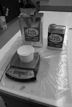
FIGURE 11-36 Weighing resin parts A and B for correct ratio. See also color insert.
Impregnation Techniques
Dry fibers are impregnated with a resin and the technician can use a brush, squeegee, or roller. It is important not to push too hard on the brush or squeegee during the impregnation process because this will distort the fiber direction and affect the strength of the repair. It is important to put the right amount of resin on the fabric. Too much or too little resin will affect the strength of the repair. Air that is put into the resin during mixing or not removed from the fabric will also reduce the repair strength.
Fabric Impregnation with a Brush or Squeegee
A brush or squeegee can be used to impregnate dry fabric with a resin system. The technician will first cut the fabric to the correct size and place the dry fabric on a sheet of release film. Resin is applied in the middle of the fabric and a brush or squeegee is used to carefully spread out the resin to cover all of the dry fabric. All of the fabric should be wetted. A second sheet of release film is placed on top of the wetted fabric and a clean squeegee is used to carefully remove air bubbles. The technician can make the lay-out for the repair on top of the release film with a marker and cut the plies. Most wet lay-up processes have a room temperature cure but extra heat will speed up the curing process and increase the properties. Temperatures up to 150°F are used to speed up the curing process. Figures 11-37a through c shows the fabric impregnation process.

FIGURE 11-37a Apply resin on top of the fabric. See also color insert.

FIGURE 11-37b Use squeegee to impregnate the fabric. See also color insert.
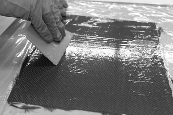
FIGURE 11-37c Place release film on top of wet fabric and use squeegee to remove air from the lay-up. See also color insert.
Fabric Impregnation Using a Vacuum Bag
The vacuum-assisted impregnation method is used to impregnate repair fabric with a two-part resin while enclosed inside a vacuum bag. This method is preferred for tight-knit weaves and when near optimum resin-to-fiber ratio is required. Compared to squeegee impregnation, this process reduces the level of entrapped air within the fabric and offers a more controlled and contained configuration for completing the impregnation process.
Procedure
• Place vacuum bag sealing tape on the table surface around the area that will be used to impregnate the material. The area should be at least 4 in larger than the material to be impregnated.
• Place an edge breather cloth next to the vacuum bag sealing tape. The edge breather should be 1 to 2 in wide.
• Place a piece of solid release film on the table. The sheet should be 2 in larger than the material to be impregnated.
• Lay the fabric on the parting film.
• Weigh the fabric to find the amount of resin that is necessary to impregnate the material.
• Pour the resin onto the fabric. The resin should be a continuous pool in the center area of the fabric. See Fig. 11-38a.

FIGURE 11-38a Pour resin in the middle of the fabric. See also color insert.
• Place a second piece of solid parting film over the fabric. This film should be the same size or larger than the first piece.
• Place and seal the vacuum bag, install vacuum port, and apply vacuum to the bag. Allow 2 min for the air to be removed from the fabric. See Fig. 11-38b.
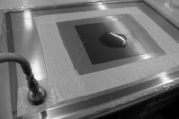
FIGURE 11-38b Apply release film and vacuum bag. See also color insert.
• Sweep the resin into the fabric with a squeegee. Start from the center and slowly sweep the resin to the edge of the fabric. The resin should be uniformly distributed over all of the fabric. See Fig. 11-38c.
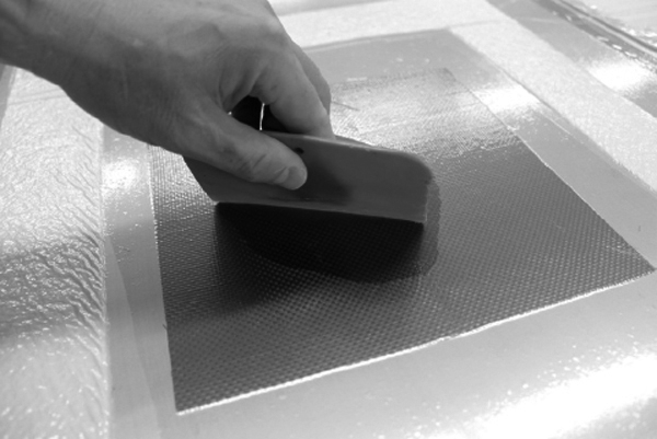
FIGURE 11-38c Use squeegee to impregnate the fabric. See also color insert.
• Open the vacuum bag and remove the fabric and cut the repair plies.
Curing of Composite Materials
The curing of a repair is as important as the curing of the original part material. Unlike metal repairs, where the materials are premanufactured, the technician is responsible for the manufacture of composite repair material. This includes all storage, processing, and quality control functions. For aircraft repairs, the cure cycle starts with material storage. Materials which are stored incorrectly can begin to cure before they are used for a repair. All time and temperature requirements must be met and documented. The aircraft structural repair manual should be consulted to determine the correct cure cycle for the part that needs to be repaired.
Room Temperature Curing
Room temperature curing is the easiest curing method. No curing equipment is necessary. However, the disadvantages of a room temperature cure cycle are: it takes a long time for epoxy resins to cure at room temperature and it will not restore either the strength or the durability of the original 250 or 350°F cure components. Room temperature cure resin systems are often used for wet lay-up fiber glass repairs for noncritical components. Room temperature cure time can be accelerated by the application of heat.
Elevated Temperature Curing
Composite repairs that use epoxy or BMI resins typically need to be cured at an elevated temperature to achieve their optimum mechanical properties. Autoclaves and curing ovens are used in the composite shop to cure repairs and heat bonders are used for on-aircraft repairs. These types of equipment use thermocouples and have a programmable computer to control the cure temperature. The technician could select a preprogrammed cure cycle recipe on the curing device or write a new program if required. Typical curing temperatures for composite materials are 250 or 350°F. The curing cycle consists of at least three segments. The first segment is the ramp up. The ramp up is often between 1 to 5°/min. The second segment is the dwell or also called soak time. This is the time the part needs to be at the maximum required temperature. The third segment is the cool down and 1° to 5° ramp down is common. Sometimes additional ramp ups and dwell time periods are added to the cure recipe. Always consult the repair manual or technical data sheet for the correct cure recipe. Figure 11-39 shows the cure recipe programmed on a heat bonder. Figure 11-40 shows the completed autoclave cure recipe.
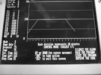
FIGURE 11-39 Heat bonder showing programmed cure recipe.

FIGURE 11-40 Completed autoclave curing recipe. See also color insert.
Curing Equipment
Autoclaves and curing ovens are the types of equipment used to cure composite repairs in the composite shop. Heat bonders are used if repairs have to be made on the aircraft and an elevated cure temperature is required. Sometimes heat lamps and hot air modules are used to cure repairs on the aircraft.
Curing Oven
Composite repair shops use programmable curing ovens to cure composite parts and repairs. The curing oven is equipped with a programmable controller to accurate control a preset curing recipe. Curing ovens can control oven temperature and vacuum. The part is vacuum bagged before it is put into the oven and the oven vacuum system will apply full vacuum during the cure. Figure 11-41 shows a curing oven.

FIGURE 11-41 Curing oven. See also color insert.
Autoclave
Autoclaves are used to manufacture most structural aircraft parts and are used by all the original equipment manufacturers (OEM) and maintenance repair stations (MRO). Autoclaves can control temperature, vacuum, pressure, and cooling. Depending on the sophistication of the autoclave these variables can be accurately controlled and adjusted to achieve an optimum cure recipe. Typical autoclave temperature goes up to 650°F and the maximum pressure could be as high as 250 psi. Most epoxy resins are cured at a maximum temperature of 350°F and a pressure of 50 to 100 psi. BMIs use higher temperatures. Autoclaves are often equipped with a nitrogen system instead of using compressed air if the autoclaves are used for temperatures above 250°F. Nitrogen is an inert gas and is used to prevent fires in the autoclave during high-temperature and high-pressure runs. Figure 11-42 shows an autoclave at a repair station.

FIGURE 11-42 Autoclave. See also color insert.
Heat Bonder
Heat bonders are used to cure composite and metal-bonded repairs on the aircraft. The heat bonder is a programmable temperature control unit that can control heat blankets, heat lamps, or hot air modules. The technician can write a cure recipe or select a program that is stored in memory. Most heat bonders also can supply and monitor vacuum. The heat bonder has alarms that go off to warn the technician that something is wrong with either the temperature or vacuum. During the cure cycle the technician should be within hearing distance of the alarm to take action immediately if the alarm goes off. The heat bonder will save the cure data and these data can also be printed out to go in the aircraft maintenance records. Figure 11-43 shows a heat bonder controlling a heat blanket.

FIGURE 11-43 Heat bonder used for curing a repair to nose radome. See also color insert.
Heat Lamps
Infrared heat lamps are used for curing composites repairs when the curing temperature is below 150°F. They are ineffective for higher temperatures because it is difficult to control the heat applied with a lamp. Heat bonders and thermocouples are often used to control the heat lamps. Lamps tend to generate high-surface temperatures quickly and their temperature profile must be studied by performing a heat survey of the repair area before the repair is accomplished. Figure 11-44 shows the use of heat lamps for curing of composites.
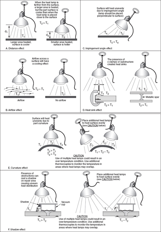
FIGURE 11-44 Heat lamp instructions for composite repair.
Hot Air Modules
Hot air module (HAM) units are generally controlled either manually or in conjunction with a heat bonder controller. They can be used to heat large areas of any contour or material. HAMs will supply controlled heat to over 900°F. HAMs are often used to heat the back side of large repair areas to reduce heat sinks. HAMs lend themselves very well to heating and curing of materials that require noncontact such as paints and coatings. When using hot air for curing of composite laminates, care should be taken not to insulate the repair by using excessive breather materials.
Heater Blanket
Heat blankets are available in many different shapes, contours, and styles. They are used to cure repairs on the aircraft. These electrical blankets are controlled by a heat bonder and thermocouples. Heat is transferred from the blanket to the aircraft via conduction. Consequently, the heat blanket must conform to and be in 100 percent contact with the part. This is usually accomplished using vacuum bag pressure. Lack of contact between the heat blanket and the area to be cured will result in inadequate heating of the repair area and an overheating of the heat blanket (Fig. 11-45).

FIGURE 11-45 Heater blankets.
Thermocouples
Thermocouples are used with autoclaves, curing ovens, and heat bonders to measure the temperature of the equipment of part. A thermocouple is a thermoelectric device used to accurately measure temperatures. Thermocouples consist of a wire with two leads of dissimilar metals; the metals are joined at one end. Heating the joint produces an electric current; this current is sent to the heat device controller.
Composite Repair
The repair of composite structures can be divided into two groups: bonded repairs and bolted repairs. Bonded repairs do not introduce stress concentrations by drilling fastener holes for patch installation and can be stronger than the original structure. The disadvantage of bonded repairs is that most repair materials require special storage, handling, and curing procedures. The preferred bonded repair method is the scarf repair. In this repair method the parent material will be tapered to create a flush repair. Bolted repairs are quicker and easier to fabricate than bonded repairs. They are normally used on composite skins thicker than 0.125 in to ensure sufficient fastener bearing area is available for load transfer. They are seldom used in honeycomb sandwich assemblies due to the potential for moisture intrusion from the fastener holes and the resulting core degradation, and low bearing area of thin face sheets. Bolted repairs are heavier than comparable bonded repairs, limiting their use on weight-sensitive flight control surfaces. Table 11-2 shows the criteria for bonded or bolted repair.
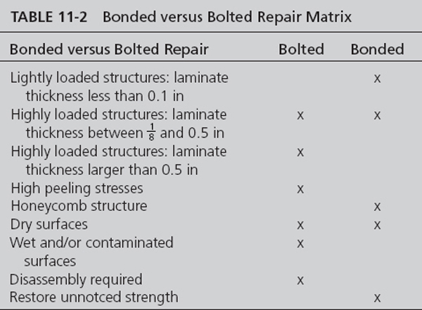
Composite Honeycomb Sandwich Repairs
Honeycomb sandwich structures are used for many aircraft components such as fairings, flight controls, radomes, and engine cowlings. These lightweight sandwich structures are susceptible to damage. Because sandwich structure is a bonded construction and the face sheets are thin, damage to sandwich structure is usually repaired by bonding. Repairs to sandwich honeycomb structure use similar techniques for the most common types of face sheet materials such as fiberglass, carbon, and Kevlar. Kevlar is often repaired with fiberglass.
Minor Core Damage (Filler and Potting Repairs)
Minor damage to a honeycomb sandwich structure can be repaired with a potted repair. The maximum size for a potted repair is typically smaller than 0.5 in. The honeycomb material could be left in place or could be removed, and is filled up with a potting compound to restore some strength. Potted repairs do not restore the full strength of the part. Epoxy resins filled with hollow glass, phenolic or plastic microballoons, cotton, flox, or other materials are often used as potting compounds. The potting compound can also be used as filler for cosmetic repairs to edges and skin panels. Potting compounds are also used in sandwich honeycomb panels as hard points for bolts and screws. The potting compound is heavier than the original core and this could affect flight control balance. The weight of the repair must be calculated and compared with flight control weights and balance limits set out in the structural repair manual.
Bonded Scarf Repair Example of Honeycomb Sandwich Panel
Honeycomb sandwich structures such as radomes, fairings, spoilers, and flight controls are often damaged and need to be repaired. The common causes of damage are: impact damage, moisture intrusion, lightning strikes, and erosion. A detailed step-by-step repair procedure is discussed below.
Step 1. Evaluate the damage through visual and NDI inspection and determine the proper repair procedure. Minor damage could be repaired using a potting repair and more substantial damage to the honeycomb sandwich structure must be repaired by replacing the core and repairing the face sheet. If the damage is so extensive that repair is not possible or economically feasible then it should be considered to remove the part from the aircraft (if it is removable) and replace with new part. The tap test or ultrasonic tests are often used to determine the extent of the damage. The damaged area can be much larger than what can be found with a visual inspection.
Step 2. The structure must be dried before the repair procedure can start. Sandwich or honeycomb panels are particularly prone to water absorption and retention due to the increased air volume in these panels. Cracked coatings, impact damage, and loose fasteners all provide paths for moisture intrusion. It is extremely important to ensure water and moisture are removed prior to performing any bonding, especially one incorporating a heated curing process. Standing water, water vapor, and absorbed moisture in laminates and honeycomb can produce the following damaging effects: blistering, delamination, microcrack damage, porosity, and weak bondline strength in the repair adhesive. Water intrusion can corrode the aluminum core. Water can travel from one core cell to the next and can travel far inside the structure over time. Sometimes small holes need to be drilled in the face sheet to drain the water before the drying operation starts. Remaining water can cause damage to the composite structure when it freezes at high altitude. Another problem with moisture is that if the repair is cured above 212°F the water can boil and the boiling pressure can disbond the face sheets from the core resulting in more damage.
Drying of the repair area can be accomplished in an autoclave or oven if the part can be taken off the aircraft. For parts of the aircraft that are not removable the water can be removed with a heater blanket and a vacuum bag as shown in Fig. 11-46. It is important to slowly turn up the heat during the water removal procedure. Consult the maintenance manual for drying times and temperatures.
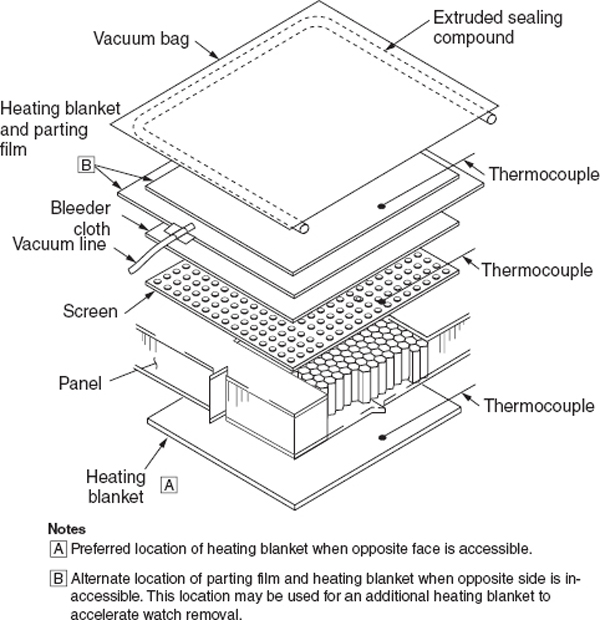
FIGURE 11-46 Water removal using vacuum bag procedure.
Step 3. Remove the damaged core and face sheet using grinders, core knives, and routers; see Fig. 11-47. Be careful not to unnecessarily enlarge the repair area during the process. Use a vacuum cleaner to remove all debris and dust.

FIGURE 11-47 Removal of damaged laminate and core.
Step 4. Honeycomb sandwich structures with thin face sheets (four plies or less) are most efficiently repaired by using a scarf-type repair. A flexible disk sander with sandpaper pad is used to taper sand a uniform taper around the cleaned-up damage. Sometimes the repair instructions give a taper ratio and other times a ply overlap is given. After the taper sanding is complete the area needs to be cleaned with a vacuum and approved solvent. Figure 11-48 shows a single-sided taper-sanded repair.

FIGURE 11-48 Single-sided taper-sanded repair.
Step 5. Use a knife to cut the replacement core. The core plug must be of the same type, class, and grade of the original core. The direction of the core cells should line up with the honeycomb of the surrounding material. The plug must be trimmed to the right length and be solvent washed with an approved cleaner before installation. A potting compound or a foaming adhesive can be used to install the replacement core plug. Usually the core replacement will be cured with a separate curing cycle and not co-cured with the patch. The plug must be sanded flush with the surrounding area after the cure. See Fig. 11-49.

FIGURE 11-49 Replacement of damaged core.
Step 6. Read the aircraft maintenance manual to determine the correct repair material, ply orientation, and the number of plies required for the repair. Typically, one more ply than the original number of plies is installed. The repair plies must be installed with the same orientation as the plies of the original structure. Repairs use either wet lay-up or pre-preg material. Impregnate the plies with a resin system for the wet lay-up repair or remove the backing material from the pre-preg material. Often extra plies of fiberglass are added on top of the repair. These plies are not structural but are there to be sanded down after the repair is cured to achieve a smooth surface. Figure 11-50 shows the placement of repair plies.
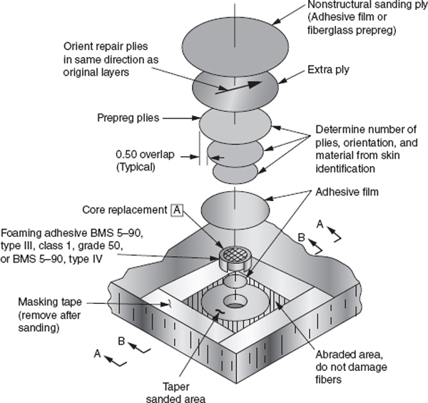
FIGURE 11-50 Repair ply placement.
Step 7. A vacuum bag (see Fig. 11-51) will be used to apply pressure to the repair to consolidate the repair plies. A heater blanket will be placed in the vacuum bag if an elevated temperature needs to be used to cure the repair. Most structural repairs use either 250 or 350° cure cycles.
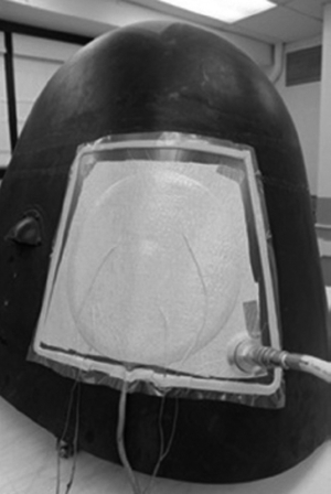
FIGURE 11-51 Vacuum bag procedure. See also color insert.
Step 8. Most aircraft structural repairs use an elevated heat cure and autoclaves or curing ovens are preferable if the part can be removed from the aircraft. A heater blanket and a heat bonder are used if the repair has to be made on the aircraft as shown in Fig. 11-43.
Step 9. Remove the vacuum bag and inspect the repair visually and with NDI equipment. A tap test might be sufficient for thin face sheets or ultrasonic or thermography inspection methods could be used. After inspection the repair patch will be sanded and a paint system will be applied. Figure 11-52 shows a completed repair on a nose radome.
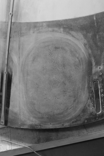
FIGURE 11-52 Repair of a nose radome. See also color insert.
Repair of Honeycomb Ramp Corner
Honeycomb panels are often damaged at the corners due to erosion, impact damage, and rough handling during maintenance. Honeycomb structures need to treated carefully and always put on racks and never on the ground during maintenance inspections. Figure 11-53 shows an example of a repair of a corner ramp.

FIGURE 11-53 Repair of corner ramp.
Repair of Sandwich Structures with Foam Core
New generations of general aviation aircraft such as the Cirrus SR 20 are made from a composite structure that consists of a fiberglass sandwich structure with a foam core. The repair procedures for these aircraft are similar to those for honeycomb sandwich structures. Figure 11-54 shows the repair scenario for these types of structures. Figure 11-55 shows the repair technique on the aircraft.

FIGURE 11-54 Repair scenarios for bonded foam cores.
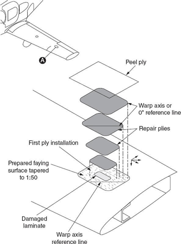
FIGURE 11-55 Placement of repair plies for bonded foam core repair.
Solid Laminates
Solid laminate structures are used extensively for new transport aircraft. Solid laminate structures ranging from 4 plies to over 100 plies are used. Thinner laminate structures can effectively be repaired with a bonded repair. Typically the repair area is scarf sanded and a flush patch is used to repair the structure. Thicker laminate structures are often repaired with a bolted repair.
Bonded Patch Repairs
Bonded repairs of carbon fiber laminate structures are often made with pre-preg materials but lower cure temperature alternative repair methods using wet lay-up are often available. The original structure is often scarved or stepped for a flush repair but external patch repairs could also be used. The advantage of the stepped repair is that the adhesive does not run down the bondline but a good step repair is hard to accomplish with manual tooling. Figure 11-56 shows an external patch repair and Fig. 11-57 shows a scarf-type repair. Figure 11-58 shows a stepped repair.
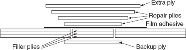
FIGURE 11-56 External patch repair for laminate structure.

FIGURE 11-57 Scarf repair for laminate structure.

FIGURE 11-58 Stepped repair for laminate structure.
Resin Injection Repairs
Resin injection repairs are sometimes used to repair minor damage to aircraft structures. Resin injection repairs are used on lightly loaded structures for small damages to a solid laminate due to delamination. Two holes are drilled on the outside of the delamination area and a low-viscosity resin is injected in one hole until it flows out the other hole. Resin injection repairs are sometimes used on sandwich honeycomb structure to repair a face sheet disbond. Disadvantages of the resin injection method are that the fibers are cut as a result of drilling holes, and it is difficult to remove moisture from the damaged area and to achieve complete infusion of resin. Field reports have indicated that resin injection repairs are often unsuccessful. Figure 11-59 shows the basic principle of a resin injection repair.

FIGURE 11-59 Resin injection repair for laminate structures.
Composite Patch Bonded to Metal Structures
Composite materials can be used to structurally repair, restore, or enhance aluminum, steel, and titanium components. Bonded composite doublers have the ability to slow or stop fatigue crack growth, replace lost structural area due to corrosion grindouts, and structurally enhance areas. Boron epoxy, GLARE®, and graphite epoxy materials have been used as composite patches to restore damaged metallic wing skins, fuselage sections, floor beams, and bulkheads. Secondarily bonded pre-cured doublers and in situ cured doublers have been used on a variety of structural geometries ranging from fuselage frames to door cutouts to blade stiffeners. Vacuum bags are used to apply the bonding and curing pressure between the doubler and metallic surface. Film adhesives using a 250°F [121°C] cure are used routinely to bond the doublers to the metallic structure. Metal treatment for bonding is critical and care must be taken to create an active surface for bonding in addition to removing contaminates.
Repairs to Bonded Metal Structures
Some aircraft use a bonded metal construction. Adhesives are used to attach metal parts together instead of rivets and bolts. These metal structures could be repaired with techniques similar to damage to riveted metal structures. A typical repair for the leading edge of a wing is shown in Fig. 11-60.

FIGURE 11-60 Leading edge repair of bonded metal structure.
Step 1. Trim out the damaged area in a rectangular pattern and deburr.
Step 2. Place the repair doubler beneath the wing skin, as shown in Fig. 11-60.
Step 3. Holding the repair doubler in place with clamps, drill  -in holes through the wing skin, spacing the holes
  in apart, center to center.
Step 4. Secure the doubler to the wing leading edge with clecos and dimple the holes. Install blind rivets to secure the doubler.
Step 5. Place the preformed filler flush with the skin over the doubler. The filler must be of the same material and thickness as the skin.
Step 6. Hold the filler in place, drill holes, and dimple the skin.
Step 7. Install blind rivets to secure the filler.
Step 8. Use epoxy filler to create a smooth surface and restore the paint system.
Repairs Using Pre-cured Patches
Pre-cured composite patches can be used to repair damaged composite structures; see Fig. 11-61. The advantages of the pre-cured patch are that they can be made in advance in the autoclave, they have the same mechanical properties as the original aircraft structure, and it is relatively easy to bond the patch to the aircraft. The difficulty in this type of repair is the fit of the patch to the aircraft structure. The patch needs to follow the contour of the aircraft perfectly to accomplish a good bondline. For this reason these patches work best on flat or lightly contoured structures.
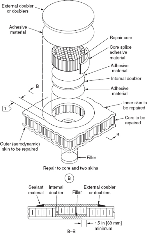
FIGURE 11-61 Repair using procured patches.
Bolted Repairs
Bolted repairs are often used on thick composite laminate structures such as primary wing, stabilizer, and fuselage structures on transport aircraft. The repair scenario for the bolted repair is similar to repairing an aluminum aircraft. Both composite patches and metallic patches are used. Titanium patches are often used with aircraft with a carbon fiber structure. The technician will have to prepare the external patch, layout the rivet pattern, drill the fastener holes, and install the fasteners. Advantages of the bolted repair are that technicians are already familiar with the repair technique, it is quicker to accomplish without the need for a temperature controlled environment, and heat cure is required. The main disadvantage of bolted repairs is that the new holes created in the parent structure weaken the structure by creating stress concentrations that become damage initiation sites. Figure 11-62 shows an example of a bolted repair. Conventional rivets installed with rivet guns, such as those used in a metal repair, cannot be used because the impact of the rivet gun will damage the composite structure. Laminate structure is often reinforced with stringers and stiffeners, and these are often damaged at the same time when the laminate skin is damaged. These stringers are often co-cured with the skin and cannot easily be replaced and need to be repaired. Repair techniques are similar to metal stringer repairs. Figure 11-63 shows an example of a stringer repair.

FIGURE 11-62 Example of a bolted repair.

FIGURE 11-63 Stringer repair with titanium formed channel. See also color insert.
Fasteners Used with Composite Laminates
Many companies make specialty fasteners for composite structures and several types of fasteners are commonly used; threaded fasteners, lock bolts, blind bolts, blind rivets, and specialty fasteners for soft structures such as honeycomb panels. The main differences between fasteners for metal and composite structures are the materials and the footprint diameter of nuts and collars. Neither fiberglass-reinforced nor Kevlar fiber–reinforced composites cause corrosion problems when used with most fastener materials. Composites reinforced with carbon fibers, however, are quite cathodic when used with materials such as aluminum or cadmium, the latter of which is a common plating used on fasteners for corrosion protection.
Fastener Materials
For repair of composite parts the choice of fasteners is limited to titanium, Monel, or stainless steel. Titanium alloy Ti-6Al- 4V is the most common alloy for fasteners used with carbon fiber–reinforced composite structures. Ti-3Al-2.5V and commercially pure titanium are used for some components of fastening systems. When higher strength is required, materials such as A286 or alloy 718 that have been strengthened by cold working can be used.
Drilling
Drilling holes in composite materials is different from drilling holes in metal aircraft structures. Different types of drill bits, higher speeds, and lower feeds are required to drill precision holes. Composite materials are drilled with drill motors operating between 2000 and 20 000 RPM, and a low feed rate is required. Drill motors with a hydraulic dash pod or other type of feed control are preferred because they restrict the surging of the drill as it exits the composite materials. Structures made from carbon fiber and epoxy resin are very hard and abrasive and special flat flute drills or similar four-flute drills are required. Aramid fiber (Kevlar)/epoxy composites are not as hard as carbon but are difficult to drill unless special cutters are used because the fibers tend to fray or shred unless they are cut clean while embedded in the epoxy. Special drill bits with “clothes pin” points and “fish tail” points have been developed that slice the fibers prior to pulling them out of the drilled hole. If the Kevlar/epoxy part is sandwiched between two metal parts, standard twist drills can be used. The quality of the drilled hole is critical; therefore, each hole should be visually inspected to ensure correct hole size and location and proper normality, as well as the absence of unacceptable splintering or fiber breakout, fiber pullout, delaminations, back counter-boring, evidence of heat damage, and microcracking. Delamination, separation of bonded composite plies, may occur at the drill entrance due to too fast of a feed rate for the speed, or at the drill exit due to too much feed force on unsupported materials. Splintering or fiber breakout conditions, fibers that break free from the surrounding resin matrix, may occur at the drill entrance or exit, especially in unidirectional material. Figures 11-64 show drill types used for composite materials. Larger holes can be cut with diamond-coated hole saws or fly cutters, but only use fly cutters in a drill press and not in a drill motor. A hole saw can easily remove damage from 1 to 3.5 inches in diameter in a very neat, uniform manner. The material being cut should be well supported and firmly backed up with wood or an aluminum plate to prevent backside breakout. Hole saws may also be used to cut through the core for damage removal, but only when the damage removal cut is to be made perpendicular with the skin.
Drill Types
Drilling and trimming of composite materials is difficult because standard tool steels will dull rapidly in the process. Problems can occur because of the way drills are shaped and sharpened. As a drill dulls, it tends to push against the material rather than cut, causing layer delimination. The drill bit should be shaped in a spade form (Fig. 11-64a) or a long tapered form sometimes referred to as a dagger drill (Fig. 11-64b). Diamond-tipped equipment will allow more cuts to be taken per tool. When drilling carbon fiber material, it is best to use a high-speed, automatic feed drill motor. Kevlar is difficult to drill and a special ground drill bit is used (Fig. 11-64c). These sickle-shaped Klenk drill bits will first pull on the fibers and then shear them, which results in a better quality hole. This type of drill bit is best when drilling aramid materials as it minimizes fiber fuzz.

FIGURE 11-64a Dagger bit.
FIGURE 11-64b Spade drill.
FIGURE 11-64c Klenk point bit for aramid (Kevlar) fibers (brad point).
Countersinking
Countersinking a composite structure is required when flush head fasteners are to be installed in the assembly. For metallic structures, a 100° included angle shear or tension head fastener has been the typical approach. In composite structures, two types of fasteners are commonly used: a 100° included angle tension head fastener or a 130° included angle head fastener. Carbide cutters are used for producing a countersink in carbon/epoxy structure. For carbon/epoxy structure, the countersink cutters usually have straight flutes similar to those used on metals. For Kevlar fiber/epoxy composites, S-shaped positive rake cutting flutes are used. A microstop countersink gauge should be used to produce consistent countersink wells.
Repair Safety
Composite materials can often be toxic. The typical health areas at risk are vision, dermal (skin), and respiratory. Resins, solvents, initiators (i.e., MEKP), dust, and particles commonly cause visual risks. Visual problems are accompanied by symptoms such as watering, redness, swelling, itching, and burning of the eyes. Chemical goggles and glasses with side shields are effective in protecting the eyes from direct contact with the risks mentioned above. However, vapors coming from these materials can still be harmful. Dermal risks are commonly caused by fibers, coatings, chemicals (resin, solvents, and mold release), foams, and dust. Dermal problems are accompanied by symptoms such as redness, rash, itching, burning, and dryness or cracking of the skin. Protection from these risks are done by covering exposed skin, gloves (latex and other types), and barrier cream. Respiratory risks are commonly caused by (1) fumes and vapors (chemical and generated by grinding) and (2) dust and particles (grinding and glass bubbles). Respiratory problems are accompanied by symptoms such as headache, nausea, tightness in the chest, troubled breathing, shortness of breath, and dizziness. Avoiding prolonged exposure and selecting products with the least amount of toxicity can help reduce these risks. Other protective equipment such as a dust mask (dust and particle protection only), charcoal respirator (vapor protection for a limited period only), and supplied air mask can help in reducing respiratory risks.
Personal protection equipment (PPE) (eye protection, gloves, aprons, respirators, etc.) should be worn during handling and repair of advanced composite materials. The PPE required to safely handle a specific material is provided in the supplier’s material safety data sheet (MSDS) and should be consulted to determine the PPE to use. During composite repair work the skin needs to be protected from hazardous materials. Always wear gloves and clothing that offer protection against toxic materials. Use only approved gloves that protect your skin and do not contaminate the composite material. Always wash your hands prior to using the toilet or eating. Chemicals could remain on your hands that will burn sensitive skin. Make sure that the gloves do not contaminate your composite materials. Damaged composite components should be handled with care. Single fibers can easily penetrate the skin, break off, and become splinters lodged in the skin. Sharp tweezers and a magnification lens are generally required to remove the splinter. If the splinter is hard to remove, seek medical attention immediately. Accidental chemical spills, runaway exothermic reactions, and heat blanket fires are some of the potential emergencies that can be encountered during the manufacturing and repair process.
Vacuum downdraft tables, power tools with vacuum attachments, and portable vacuum systems should be used when drilling and trimming operations are performed on cured composites. Dust is created during composite processing that could cause respiratory problems that may not manifest themselves for years. Using compressed air to blow composite dust should be avoided. Blowing the dust results in the dust mixing with the air being breathed, resulting in ingestion of the materials through the lungs. Do not use compressed air to clean dust from the body or clothing. This may force dust particles into the pores of the skin.
Fire Protection
Most solvents used for composite repair are flammable. Close all containers with solvents and store in a fireproof cabinet when not used. Make sure that solvents are kept away from areas where static electricity can occur. Static electricity can occur during sanding operations or when bagging material is unrolled. It is preferable to use air-driven tools; if electric tools are used make sure that they are of the enclosed type. Do not mix too much resin. The resin could overheat and start smoking caused by an exothermal process. Always make sure that a fire extinguisher is nearby to fight a fire.
REVIEW QUESTIONS
1. Describe a composite material.
2. List some examples of aircraft components that are made of composite materials.
3. What is a quasi-isotropic lay-up?
4. What is the typical fiber orientation of a quasiisotropic lay?
5. Explain the difference between laminate symmetry and laminate balance.
6. What are the three most common fiber materials used for aerospace structures?
7. Explain why lightning protection fibers and materials are necessary for composite aircraft.
8. Explain the differences between tows, yarns, and rovings.
9. What is the difference between tape and fabric products?
10. List the most common types of weave styles.
11. Describe the role of the matrix.
12. What are the two main classes of resin systems?
13. Name the most common types of thermosetting resins.
14. Explain the three curing stages of thermosetting resin systems.
15. Explain briefly what thermoplastic resin systems are and how they differ from thermosetting resin systems.
16. What is a prepreg material?
17. Name three types of adhesive systems used in the aerospace industry.
18. Explain the difference between a honeycomb sandwich and a laminate structure.
19. When is flexcore used as a core for a part?
20. Name the typical types of manufacturing damage.
21. Name the typical types of in-service damage.
22. Explain the difference between a delamination and a debond.
23. Why are core drying cycles necessary before a part can be repaired?
24. What types of tools are used when performing a visual inspection?
25. Explain the coin tap inspection method.
26. Explain the ultra sonic inspection method.
27. What is the difference between a pulse echo, through transmission, and phase array ultrasonic inspection?
28. What type of damage can be found with an X-ray inspection?
29. Explain the basic principle of thermography.
30. What type of defects can be found with thermography?
31. Name the three damage categories.
32. Explain why air tools should be used instead of electric tools.
33. What kind of processing materials are used to vacuum bag a composite repair?
34. In what situation are peel plies used?
35. Explain what needs to be done if the vacuum bag is “bridging.”
36. Explain the vacuum bag technique used to repair aircraft structures.
37. How can the bleeding of resin during a cure of a wet lay-up be controlled?
38. Explain what a no-bleed system is.
39. Explain the envelope vacuum bag technique.
40. Explain the heat shrink method to apply pressure to a lay-up.
41. Briefly explain the wet lay-up process.
42. What type of materials must be stored in a freezer to retard curing?
43. What is the typical storage life of prepreg?
44. Explain the differences between co-curing, cobonding, and secondary bonding.
45. What are the disadvantages of room temperature curing?
46. What type of resin systems need to be cured at an elevated temperature?
47. Name four types of curing equipment to cure composite materials.
48. Describe what an autoclave can control during the curing process.
49. Why are heat lamps not efficient above 150°F?
50. Heat blankets are used with what type of curing equipment?
51. Composite repairs can be divided into what two groups?
52. What are the advantages of a bonded repair?
53. What are the advantages of a bolted repair?
54. What type of repair is typically used for honeycomb sandwich structure?
55. Explain the potted repair process.
56. Describe the repair steps used for a bonded repair.
57. What are the advantages of a stepped repair?
58. What are the disadvantages of a resin injection repair?
59. Describe the repair steps for a bolted repair of a composite structure.
60. What is the difference between fasteners used for metal and composite structures?
61. What type of fastener material is used for aircraft using a carbon fiber structure?
62. What type of drill bit is used to drill Kevlar?
63. Describe what type of personal protective equipment must be worn by the technician when handling composite materials.
..................Content has been hidden....................
You can't read the all page of ebook, please click here login for view all page.