

Troubleshooting Theory and Practice |
19 |
INTRODUCTION
Whenever a malfunction or discrepancy is reported or comes to the attention of the technician, no matter how simple or how complex, the process of troubleshooting begins. The technician must determine the discrepancy’s effect upon the airworthiness of the aircraft and the appropriate time and location for the corrective action to be taken.
THE TROUBLESHOOTING PROCESS
Troubleshooting is the process of identifying the cause of a malfunction or discrepancy, determining its severity, eliminating the cause, replacing or repairing discrepant components, systems, or structures, and, finally, returning the aircraft to service. The ultimate object of troubleshooting in aviation is to return aircraft to an airworthy condition offering a high probability that the malfunction or discrepancy will not recur. Although the technician cannot ensure that the malfunction or discrepancy will never recur, returning an aircraft to service with a high probability that the malfunction will be experienced again cannot be considered successful troubleshooting. In fact, if the discrepancy is an airworthiness item, returning the aircraft to service with a high probability of premature failure may be tantamount to returning the aircraft to service in an unairworthy condition.
Troubleshooting is more than just replacing a malfunctioning component or making a repair. Whether the thought process is evident or not, the first step in troubleshooting is to identify the cause of the discrepancy. The cause of the discrepancy can be as simple as “worn out through usage” or complex enough to involve more than one aircraft system.
For example, a landing-gear position-indicating switch may fail because of its frequent usage, or the failure may be premature, with the true cause of the failure being a voltage regulator or perhaps a leak in the hydraulic system allowing hydraulic fluid to drip on the switch. It is important that the technician identify the true cause of the discrepancy when determining the corrective action to be taken.
The second step in the troubleshooting process is to evaluate the reported discrepancy to determine if it has an adverse effect upon the aircraft’s airworthiness. If the technician’s evaluation determines that existence of a discrepancy does render the aircraft unairworthy, the technician must continue with the third step of the troubleshooting process. (It might be argued that the second step is truly the first step in the troubleshooting process. In the determination that an aircraft is unairworthy, this step may, indeed, be the first step. However, to determine that an aircraft is airworthy, a knowledge of the cause also is necessary.)
If the discrepancy adversely affects the airworthiness of the aircraft, corrective action must be taken before its next flight. The one exception is when the discrepancy is sufficient to render the aircraft unairworthy for normal flight, but under special FAA authorization (see Aircraft Basic Science) it may be flown (ferried) to a location where facilities are available for corrective action.
However, if the discrepancy does not affect the airworthiness of the aircraft, the technician is faced with another decision. This decision is the determination of whether or not the discrepancy should be repaired immediately or deferred to a later date. There are a number of factors that affect this decision-making process. The two major considerations are: Is the appropriate equipment available? Is there sufficient time available to perform the required activities properly?
The Use of Troubleshooting Charts
Many aircraft manufacturers include, as part of the maintenance and training manuals, troubleshooting charts designed to help the technician identify failed components. Figure 19-1 is an example of a troubleshooting chart supplied by Sikorsky Aircraft Corporation. It is important that the technician again note the distinction between failed component identification and identifying the cause of the discrepancy. These charts, when considered by themselves, typically fall short in the identification of the cause for the failure.
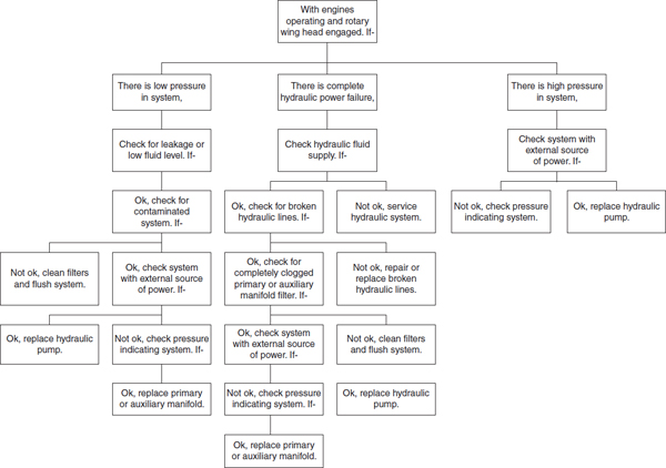
FIGURE 19-1 Troubleshooting chart. (Sikorsky Aircraft Corp., Division of United Technologies Corp.)
The location of this chapter as the final chapter in this book is not by accident. In order to take the necessary steps in the troubleshooting process, a thorough understanding of aircraft systems is required. The technician must use the information found in this text, personal experience and training, and information in the maintenance manuals, service bulletins, etc., to identify the cause of a discrepancy. Frequently, when manufacturers include a troubleshooting chart in the maintenance manual, a written description of the actions to be taken is included. It is important that the technician read the associated information and not refer solely to the graphic display.
For example, again referring to Fig. 19-1, assume that the following scenario exists: The system is experiencing low pressure, the fluid level is adequate, and no leakage is evident, but contamination is found in the system. According to the graphic troubleshooting chart, the technician is to clean filters and flush the system. If the technician follows only those instructions, the troubleshooting process has not been properly completed. The technician must analyze the contamination to determine its nature and source; the corrective action should include elimination of the source of the contamination.
Troubleshooting charts help identify common malfunctions. However, the technician may be confronted with situations that are not reflected by troubleshooting charts. In such instances, the technician must have a thorough knowledge of the system, its components, its operations, and its relationship to other systems.
Troubleshooting without a Chart
When attempting to troubleshoot a discrepancy without the aid of a troubleshooting chart, the technician’s first step is to decide where to begin the analytical process. This decision may be based upon the technician’s personal experience or made by heeding the advice of more experienced technicians. When experience does not suggest the point at which the troubleshooting should begin, the technician should consider the divide-and-conquer technique.
In the divide-and-conquer technique, the technician separates the system into two equal parts, either in regard to the number of components or in terms of a linear measurement, and then tests the operation of each half of the system to that point. Based upon the results of the test, the technician knows whether the discrepancy lies in the first or second half of the system being tested. The discrepant half of the system is then divided into two equal parts and the system is again tested. This process is repeated until the discrepancy is discovered. The use of the divide-and-conquer technique offers, in the long run, the quickest way to identify a discrepancy and its possible cause.
When coupled with experience, the divide-and-conquer technique is hard to beat. The technician may, after previous troubleshooting, note that one portion of a system rarely experiences failure. In such cases troubleshooting testing may begin at some other, more likely point.
Testing at any point in the system requires knowledge of the specific system involved. The technician must be able to determine the inputs and outputs of the system at the test point. Generally, it is better for the technician to determine what is to be expected at any point prior to making the test. Determining the acceptable test result criteria before testing lessens the tendency of the technician to accept invalid results. If the technician errs in establishing the test criteria, little harm is done if the system is operating properly up to that point; when the error is identified the technician will have a better understanding of a system’s operations.
The selection of the appropriate corrective action is the next step in returning the aircraft to an airworthy condition. A discussion of corrective (repair) techniques is beyond the scope of this chapter. Previous chapters typically will contain the appropriate corrective techniques. However, the technician should remember that the repair is not complete until the cause and the symptom are corrected.
Figure 19-2 helps demonstrate the divide-and-conquer technique. Assume the pilot reports that a left-hand low-pressure warning light flickers. Also assume that all valves are in the position shown in the figure. The obvious things are checked first: fuel supply and warning light bulb, and both are functional. Note that the troubleshooting chart says nothing about flickering. From the system schematic, it is determined that there are four locations from which troubleshooting may be accomplished: the engine compartment, the cockpit, and either of the two fuel-tank areas.
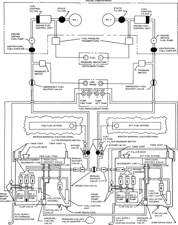
FIGURE 19-2 Schematic diagram of fuel system for S61-N helicopter. (Sikorsky Aircraft Corp., Division of United Technologies Corp.)
Step 1A. Divide and conquer by selecting the cockpit as the middle location. Since the difficulty appears on the left-hand system, the right-hand emergency shutoff valve is closed and tagged (tagging of all switches and manual valves placed in nonoperational positions during the troubleshooting process is accomplished to ensure that they are returned to the operational positions before the aircraft is released for service). When the fuel-boost pumps (all four) are activated, the discrepancy is not duplicated.
Step 1B. When the left-hand emergency shutoff valve is also closed (something that is not likely to be done in flight) the low-pressure light illuminates but does not flicker. Chances are now good that the fault does not lie in the engine compartment. The emergency shutoff valve is opened.
Since no master warning of fuel bypass was reported, fuel bypass systems are assumed to be operational. The discrepancy may now be assumed to be in either of the fuel-tank systems.
Step 2A. Each system may be checked separately by use of the cross-feed valve. With the cross-feed valve open, the left-hand boost pumps are turned on (right-hand boost pumps are off). The discrepancy is not duplicated. From this the left-hand system and the right-tank check valve (CV) may be considered operational.
Step 2B. Turning off left-hand pumps and turning on the right-hand pumps results in the problem being duplicated. The problem lies in either the right-hand tank or the left-hand check valve.
Step 2C. Closing the left-hand manual shutoff valve, the discrepancy continues, so the left-hand check valve is probably operational.
Step 3. Closing the cross-feed valve and opening the right-hand emergency shutoff valve moves the discrepancy from the left-hand low-pressure light to the right-hand light. The discrepancy is definitely in the right-hand tank system. However, since the tank boost pumps do not indicate failure, the boost pumps are probably all right. The two remaining potential problems are the two check valves, either the fuel-ejector unit check valve or the check valve between the boost-pump check valves.
By dividing the system in half at the emergency shutoff valve, the portion of the system beyond the emergency shutoff valve was eliminated from consideration. By dividing the faulty portion of the system in half again, the right-hand tank system was identified as the culprit. A cross-check verified this fact. After dividing the system in half twice and doing a little analysis, the technician was thus able to limit the fault to one of two components from a potential of slightly fewer than 50 components.
The important aspect of this example is not the use of this particular schematic for this particular discrepancy, but rather to illustrate the advantages of using the divide-and-conquer technique as opposed to a hit-and-miss approach to troubleshooting.
Operating Data Helpful in Troubleshooting
In troubleshooting, it is most helpful to have a good overall knowledge of the particular airplane and aircraft type in which the trouble is encountered. Just as a physician, in diagnosing an illness of a patient, tries to obtain a knowledge of the patient’s general health before prescribing a remedy for the particular ailment, so should technicians learn the various operating weaknesses (if any) of the airplanes they customarily repair. This information is obtained by personal observation, from conversations with the pilots, from the flight record forms, and from various technical publications.
Troubleshooting Intermittent Discrepancies
The experienced technician knows—and the novice technician will soon find out—that the most difficult discrepancies to locate and correct are intermittent discrepancies. One minute the discrepancy exists; the next minute everything seems to be working properly.
The first step in troubleshooting intermittent discrepancies is to gather as much information as possible regarding the nature, frequency, and duration of the discrepancy. Even the weather, especially humidity, precipitation, and temperature, before and during the discrepancy should be considered. To troubleshoot intermittent discrepancies without this information is guesswork, not troubleshooting.
Analyze this information for patterns. Intermittent discrepancies result most often as a result of heat, vibration, and weather. Look for patterns, such as during take-off and landings, changes in altitude, and during and after flight maneuvers.
If the discrepancy seems to relate to vibration, check components for security first. Operate as many moving parts as possible, checking for security and wear. For example, a bolt that acts as the axis for a pulley may be worn in one spot, allowing it to rotate when there is vibration and no tension on the pulley. If, when the tension is applied to the pulley, the pulley mates with the bolt in the worn spot, the associated rigging is adversely affected. After the tension is released, the bolt may rotate randomly. If the next time tension is applied to the pulley, the pulley and bolt mate at a nonworn surface, the system might work properly.
Heat, another major cause of intermittent discrepancies, generally causes intermittent discrepancies due to thermal expansion. One component of heat-related intermittent discrepancies is the ambient temperature. A heat-sensitive discrepancy may exist when an engine, for a few minutes, ran hot on a hot day, but operated fine after the same amount of operation on a cool day. Information similar to this will help the technician know where to concentrate troubleshooting efforts. In this case, since the discrepancy occurs only when the powerplant has been running, the technician can concentrate troubleshooting in the areas where heat from the engine is concentrated. By noting the ambient temperature relationship in the discrepancy, the technician might start first in areas where ambient air provides engine compartment cooling.
In troubleshooting intermittent discrepancies, the technician should realize that the discrepancy is the effect of not one but at least two causes. One cause will be the failure of the system itself (or the thing that needs to be repaired or replaced); the other cause(s) will be intermittent, whether by design (such as vibration caused by landing) or chance (such as the way the sun hits an electrical component, providing just enough additional heat to cause the discrepancy to reoccur). The successful troubleshooter of intermittent discrepancies looks for both causes, not just one.
Validation of Troubleshooting Results
The final step in the troubleshooting process is the validation that the analytical steps of the troubleshooting process were properly interpreted. This often results in the necessity for some type of operational check. The procedures for such a check should be specified in the aircraft’s maintenance manual. When operationally checking intermittent discrepancies, the check needs to include the suspected causes.
FOTMAT OF TROUBLESHOOTING CHARTS
The generic use of troubleshooting charts was discussed earlier in this chapter. As part of that discussion, Fig. 19-1 was used to identify potential causes of a malfunction. Figure 19-1 is one of the three most popular formats used to display troubleshooting logic. These popular formats are the flow, pick, and binary formats.
The flow format used in Fig. 19-1 is a relatively simple format. Using this format the technician begins with an assumed condition, in this case “with engines operating and rotary wing head engaged,” and then proceeds through a series of checks. Each check leads to an “OK” or “NOT OK” determination. The OK determinations lead the technician through the appropriate vertical logic path. The presence of a NOT OK determination changes the direction of the troubleshooting path to a horizontal path, leading to suggested corrective action.
Figure 19-3 is an example of a pick-type troubleshooting chart. This chart is composed of three columns. The first column indicates the nature of the discrepancy. The second column indicates the possible causes for the discrepancy. The third column indicates the corrective action typically required to correct the cause of the discrepancy. The vertical lines separate the causes and remedies into the appropriate trouble groupings.
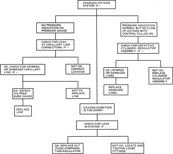
FIGURE 19-3 Troubleshooting chart for a stored-gas oxygen system in a light airplane.
There are two major differences between the flow and pick formats. The flow format has a tendency to follow the aircraft system’s operational sequences. As a result, system schematics may be used to complement flow formats. Flow formats may also be constructed so that the most frequent cause for a discrepancy or malfunction is listed early in the troubleshooting sequence. Note that the pick chart in Fig. 19-3 does not identify the relative probabilities of the causes of problems.
The third format used for troubleshooting is the binary logic chart. Binary logic charts (as illustrated in Fig. 19-6) are used to troubleshoot systems that operate based upon a logic. This logic may be used when the status of two or more functions determines the operational condition of another function. Binary logic may be used in electrical, pneumatic, and hydraulic system applications. The major benefit derived from the use of a binary logic chart for troubleshooting is that component inputs and outputs are easily identified. This will become clearer later in this chapter. The major weakness of using a binary logic chart as a troubleshooting tool is the same as for the pick chart: The relative probability of a discrepancy’s cause is not indicated.
Binary logic charts have six primary decision criteria called gates. A gate has channels through which inputs are received. The signal processed through the channel either exists or is absent. If a signal exists, then it is said to be input. The absence of a signal, although used by the gate in determining whether or not its decision criteria is met, is said not to have input. In mathematical terms, if the channel is producing input it has a value of 1. A channel not producing input has a value of 0, so it is said not to have input. Technicians familiar with Boolean algebra will recognize this logic.
There are two basic decision gates, one invert gate, three complementary gates, and an infinite number of gate variations. Four of these variations are included in Fig. 19-4 and are discussed in more detail later.
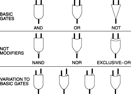
FIGURE 19-4 Symbols for binary logic gates.
When the input meets the requirements of the decision criteria (gate), there is an output. If the gate’s input requirements are not met, there is no output. Although there may be more than one input, there may be only one output.
There are three basic types of gates:
1. The AND gate has an output only when all inputs exist.
2. The OR gate has an output if any or all expected inputs exist.
3. The NOT gate simply inverts (or changes) the output.
4. NOT gates are also referred to as invert gates. If there is no input to a NOT gate, there is an output. If input exists, the NOT gate has no output.
The technician should note the circle at the bottom (output) of the NOT gate. A circle at an input or an output indicates an invert gate precedes (for inputs) or follows (for outputs) the basic gate decision criteria.
The three complementary gates are slight modifications to or combinations of the three basic gates:
1. The NAND gate has an invert (NOT) gate immediately prior to the AND gate. In other words, the NOT gate (indicated by the circle) output is the input for the AND gate.
2. The NOR gate places a NOT gate immediately prior to an OR gate.
3. The EXCLUSIVE-OR gate operates in the same manner as the OR gate, except that if both inputs meet the decision criteria, there is no output.
When reviewing the three complementary gates, the technician should note a pattern that repeats in the gate variations shown at the bottom of the figure—that is, there are two basic “decision” functions, AND and OR. A circle at an input places a NOT gate prior to the basic decision gate and as a result reverses the input (creates an input if one does not exist or deletes one if one exists).
For example, assume that a pneumatic system has the symbol variation at the lower right corner of Fig. 19-4. Because the system is a pneumatic system, the presence or absence of air pressure is the input and output. The basic gate is an AND gate, so if all inputs to the basic gate have air pressure, the output will be air pressure. If either input does not have pressure, there will be no output. In this variation note that the rightmost input has an invert gate. Possible scenarios for this gate are listed here, where P indicates the existence of pressure and NP indicates no pressure (input).
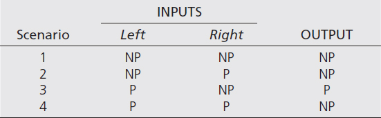
Note that in scenario 4, even though both inputs to the basic gate might initially appear to be P, the right-hand invert gate changes the right-hand input to the AND decision gate from pressure to no pressure. The opposite is true for scenario 3. The NP is changed to P before entering the decision gate.
The layout of all possible scenarios for a decision gate is called a truth table. A more complete discussion of logic gates, truth tables, and their use in electrical systems can be found in the text Aircraft Electricity and Electronics. The symbols used in binary logic charts for hydraulic and pneumatic systems follow the same pattern as those used in electricity and are shown in Fig. 19-4.
A pneumatic starting system for a three-engine gas-turbine aircraft is shown in Fig. 19-5. A review of the schematic shows that there are five pneumatic power sources that may be used to start any engine. These power sources are the auxiliary power unit (APU), a ground pneumatic unit (GPU) connected to either connection 1 or 2, and bleed air from either of the two remaining engines.
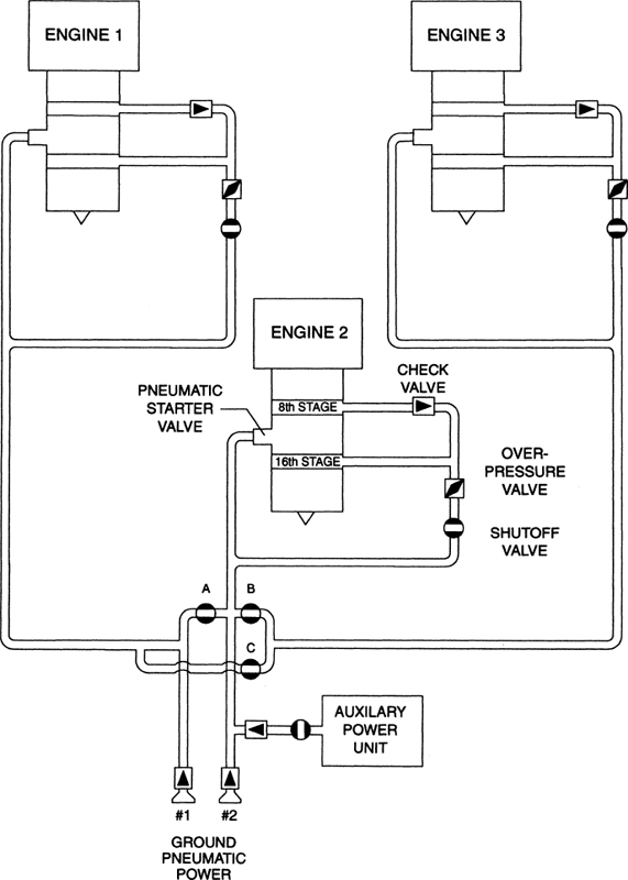
FIGURE 19-5 Pneumatic starting schematic for a three-engine gas-turbine aircraft.
The binary logic chart shown in Fig. 19-6 depicts the binary logic corresponding to the pneumatic starting of engine 2. The broken lines in the figure would not normally be present in a binary logic chart found in an aircraft’s maintenance manual. They have been included in this figure to segregate the power sources for the following discussion. The binary logic associated with the components used in an APU start is bordered by a simple dashed line. The binary logic for starting engine 2 with air supplied by engine 1 is bordered by a line consisting of a dash and a dot. The dotted lines segregate the binary logic for a start using engine 3 as the air source. The two GPU sources are between the APU and engine-start blocks. To help identify the various logic gates, logic decision levels have been segregated into levels. The levels are separated by lines with two dots between each dash.
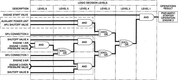
FIGURE 19-6 Binary logic chart for starting engine 2 using pneumatic start for a three-engine gas-turbine aircraft.
Note that all five pneumatic power sources are routed through a series of EXCLUSIVE-OR gates. This is because only one source may be used at a time to start an engine pneumatically. If this were not so, the EXCLUSIVE-OR gates could be replaced with OR gates. Typically, this limitation would be accomplished as part of the associated electrical systems. However, multiple EXCLUSIVE-OR gates are shown in three levels in Fig. 19-6 to demonstrate the compounding effect of binary decision gates. In an aircraft’s maintenance manual, decision levels 2 and 3 would most likely be combined and indicated by showing four inputs to a single gate.
Before the pneumatic starter will operate, two inputs must exist. The engine starter valve must be on and there must be a pneumatic air source. This fact is depicted in the binary logic chart in level 1 by the AND gate. The first logical step in troubleshooting the pneumatic starter system is to ensure that the starter valve is operational.
It is logical to assume that if trouble occurs when attempting to start the engine pneumatically and all five pneumatic systems are used in the attempt, the fault probably lies in the starter valve or the pneumatic starter motor systems. The following discussion assumes that the engine start valve is providing input (is operational and on) to the level 1 AND gate.
If the starter valve system is operational, the fault must lie within the binary logic of the associated air source. In the case of an APU start, either the APU shutoff valve is closed, the APU is not running, the APU is not supplying sufficient air to be considered a valid input, or there is a malfunction of the associated EXCLUSIVE-OR devices. Failure in the case of a GPU connector 2 start is most likely the fault of the associated EXCLUSIVE-OR devices.
In further discussions it is assumed that all logic decision gate devices are functional and operating properly.
Failure of the pneumatic starter system when attempting a start using engine 3 air might result from one of three sources: Engine 3 is not providing enough air to be interpreted by the logic gate as a valid input; the shutoff valve B is not open (thus not allowing an input); or the overpressure valve is open. If the technician is not careful in the interpretation of the logic chart, the last fault option might easily be misunderstood.
Note that the AND gate for an engine 3 start is a variation of the standard gate. There are three inputs to the logic gate, but the center input (from the overpressure valve) is an inverted input. If the overpressure valve is providing an output, then the AND gate does not receive an input because the invertor negates the input. On the other hand, if the overpressure valve is not generating an output, the invert gate will generate an output to the AND gate. If the overpressure valve generates an output when open, then the valve must be closed for the AND gate to receive an input. In the open position, the output of the overpressure valve will be reversed by the inverted gate and no input will be received by the AND gate, resulting in no output being generated by the AND gate.
For either a GPU 1 connection start or an engine 1 start, shutoff valve A must be open, providing an input to the AND gate. In addition, the level 5 EXCLUSIVE-OR gate must receive an input from either GPU connector 1 or the engine 1 air system, but not both. Input from GPU connector 1 goes directly to the gate. Engine 1 air input must pass through the level 5 AND gate. Note that the level 5 AND gate is a modified gate because there is an invert gate in the overpressure valve input to the gate.
Although the use of binary logic charts in troubleshooting may initially seem awkward to the technician, this is usually a result of the technician’s lack of familiarity with the basic logic symbols. Once the technician becomes familiar with the symbols and is adept at interpreting basic logic charts, use of logic charts can simplify the troubleshooting process.
Transport aircraft are often equipped with a centralized maintenance system and the following discussion will describe the centralized fault display system (CFDS) used on Airbus aircraft. Boeing and other aircraft manufacturers have similar systems installed on their aircraft models.
Centralized Fault Display System
The purpose of the CFDS is to make the maintenance task easier by displaying fault messages in the cockpit and permitting the flight crew to perform some specific tests. The CFDS has two levels of maintenance: removal and replacement of equipment and troubleshooting.
The CFDS includes
• BITE (Built-in test equipment). Modern transport aircraft and business jets use BITE for most of the avionics and electrically controlled systems. These BITE systems monitor themselves as well as the aircraft systems and indicate a system fault on the maintenance computer and ECAM/EICAS pages. Although the BITE system is a great resource for aircraft technicians, it does not mean that no system knowledge is required for troubleshooting. Just relying on BITE and changing parts is not a good solution. Often the BITE guides the technician in the right direction but the technician will still have to use a diagnostic manual and troubleshooting logic to solve the malfunction.
• A central computer, also called the centralized fault display interface unit (CFDIU).
• Two MCDUs (multi-purpose control and display units).
• One printer.
Figure 19-7 shows the architecture of the CFDS.
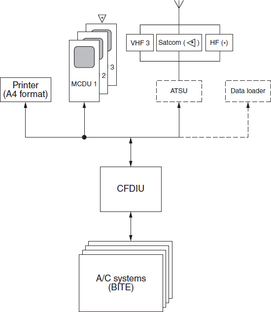
FIGURE 19-7 Architecture of CFDS.
CFDS Operation
The CFDS operates in two main modes:
1. The NORMAL mode or REPORTING mode (in flight). In NORMAL mode, the CFDS records and displays the failure messages transmitted by each system BITE.
2. The INTERACTIVE mode or MENU mode (on ground). In INTERACTIVE mode, the CFDS allows any BITE to be connected with the MCDI in order to display the maintenance data stored and formatted by the BITE or to initiate a test.
The CFDS identifies the faulty system and puts any failures or faults into one of three classes:
1. Class 1. Failures indicated to the flight crew by means of the ECAM, or other flight deck effect. These failures must be repaired or entered in the minimum equipment list (MEL) before the aircraft can depart.
2. Class 2. Faults indicated to maintenance personnel by the CFDS, and which trigger a MAINT status entry on the maintenance part of the ECAM maintenance page. The aircraft can operate with these faults but must be repaired within 10 days.
3. Class 3. Faults indicated to maintenance personnel by the CFDS, but which do not trigger a MAINT status. The aircraft operator may have these faults corrected at their convenience.
The main functions of the CFDS are as follows:
• Obtaining and storing messages transmitted by the connected systems BITEs, or by the flight warning computer
• Detailing the maintenance phases
• Presenting maintenance reports: last leg report, last leg ECAM report, previous leg report, avionics status, system report test, and post-flight report. Figure 19-8 shows a last leg report generated by the CFDS. The last leg report (on the ground) or the current leg report (in flight) lists all class 1 and class 2 faults and all system failures and system fault messages received by the CFDS during the last flight leg or the current flight leg. The report can be printed out in the cockpit. One of the main advantages of the CFDS is that maintenance is already informed during the flight of possible maintenance issues and troubleshooting and ordering of replacement parts can be started before the aircraft arrives at its destination. Figure 19-9 shows a CFDS post-flight report which is used by maintenance to troubleshoot malfunctions.
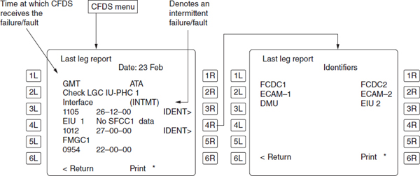
FIGURE 19-8 Last leg or current leg report.
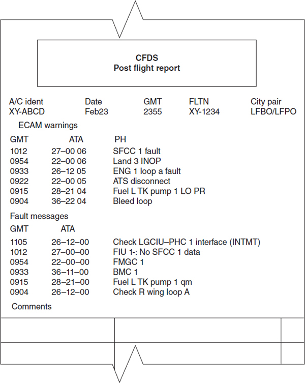
FIGURE 19-9 Post-flight report.
REVIEW QUESTIONS
1. List the steps in the troubleshooting process.
2. Why is it important to identify the cause of a discrepancy?
3. If an aircraft’s airworthiness is not affected by a discrepancy, what are the two major factors that determine when the discrepancy will be corrected?
4. What is the major weakness of troubleshooting charts?
5. What information must the technician use when troubleshooting a discrepancy?
6. Why should the technician pay attention to information on a troubleshooting chart other than the graphic logic of the chart?
7. When the technician must troubleshoot a discrepancy without the use of a chart or the information required is not on the troubleshooting chart, what process should be used?
8. Explain the benefit of using the divide-and-conquer troubleshooting technique.
9. What is the first step in troubleshooting intermittent discrepancies?
10. What must the technician look for when troubleshooting intermittent discrepancies?
11. What is the generic name given the symbol used to indicate a decision-making process in binary logic?
12. What is the function of a NOT gate?
13. Name the two primary decision gates.
14. What is the name of a table that lists all possible outputs of a binary logic gate?
15. How many outputs does a three-input AND gate produce?
..................Content has been hidden....................
You can't read the all page of ebook, please click here login for view all page.