
Chapter 5. Graphics
Computer graphics are used for any kind of display for which there isn’t a GUI component: charting, displaying pictures, and so on. Graphics tools are used to create GUI components as well as to draw shapes, lines, pictures, etc. Android is well provisioned for graphics, including a full implementation of OpenGL ES, a subset of OpenGL intended for smaller devices.
This chapter starts with a recipe for using a custom font for special text effects, followed by some recipes on OpenGL graphics and one on graphical “touch” input. From there we continue the input theme with various image capture techniques. Then we have some recipes on graphics files, and one to round out the chapter discussing “pinch to zoom,” using user touch input to scale graphical output.
5.1 Using a Custom Font
Ian Darwin
Discussion
You can provide one or more fonts with your application. We have not yet discovered a documented way to install system-wide fonts. Beware of huge font files, as they will be downloaded with your application, increasing its size.
Your custom font’s format should be TTF or OTF (TrueType or OpenType, a TTF extension). You need to create a fonts subdirectory under assets in your project, and install the font there.
While you can refer to the predefined fonts just using XML, you cannot refer to your own fonts using XML. This may change someday, but for now the content model of the android:typeface attribute is an XML enumeration containing only normal, sans, serif, and monospace—that’s it! Therefore, you have to use code.
There are several Typeface.create() methods, including:
-
create(String familyName, int style) -
create(TypeFace family, inst style) -
createFromAsset(AssetManager mgr, String path) -
createFromFile(File path) -
createFromFile(String path)
You can see how most of these should work. The parameter style is, as in
Java, one of several constants defined on the class representing fonts, here
Typeface.
You can create representations of the built-in fonts, and variations
on them, using the first two forms in the list.
The code in Example 5-2 uses the createFromAsset()
method, so we don’t have to worry about font locations.
If you have stored the file on internal or external storage (see Recipe 10.1), you could
provide a File object or the font file’s absolute path
using the last two forms in the list. If the font file is on external storage,
remember to request permission in AndroidManifest.xml.
I used the nice Iceberg font, from SoftMaker Software GmbH. This font is copyrighted and I do not have permission to redistribute it, so when you download the project and want to run it, you will need to install a TrueType font file at assets/fonts/fontdemo.ttf. Note that if the font is missing, the createFromAsset() method will return null; the online version of the code provides error handling. If the font is invalid, Android will silently ignore it and use a built-in font.
In this demo we provide two text areas, one using the built-in serif font and one using a custom font. They are defined, and various attributes added, in main.xml (see Example 5-1).
Example 5-1. XML layout with font specification
<?xml version="1.0" encoding="utf-8"?><LinearLayoutxmlns:android="http://schemas.android.com/apk/res/android"android:orientation="vertical"android:layout_width="fill_parent"android:layout_height="fill_parent"><TextViewandroid:id="@+id/PlainTextView"android:layout_width="fill_parent"android:layout_height="wrap_content"android:text="@string/plain"android:textSize="36sp"android:typeface="serif"android:padding="10sp"android:gravity="center"/><TextViewandroid:id="@+id/FontView"android:layout_width="fill_parent"android:layout_height="wrap_content"android:text="@string/nicer"android:textSize="36sp"android:typeface="normal"android:padding="10sp"android:gravity="center"/></LinearLayout>
Example 5-2 shows the source code.
Example 5-2. Setting a custom font
publicclassFontDemoextendsActivity{@OverridepublicvoidonCreate(BundlesavedInstanceState){super.onCreate(savedInstanceState);setContentView(R.layout.main);TextViewv=(TextView)findViewById(R.id.FontView);Typefacet=Typeface.createFromAsset(getAssets(),"fonts/fontdemo.ttf");v.setTypeface(t,Typeface.BOLD_ITALIC);}}

Find the
Viewyou want to use your font in.
Create a
Typefaceobject from one of theTypefaceclass’s staticcreate()methods.
Message the
Typefaceinto theView’ssetTypeface()method.
If all is well, running the app should look like Figure 5-1.
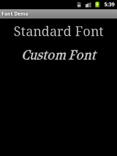
Figure 5-1. Custom font
Source Download URL
The source code for this example is in the Android Cookbook repository, in the subdirectory FontDemo (see “Getting and Using the Code Examples”).
5.2 Drawing a Spinning Cube with OpenGL ES
Marco Dinacci
Solution
Create a GLSurfaceView and a custom Renderer that will draw a spinning cube.
Discussion
Android supports 3D graphics via the OpenGL ES API, a flavor of OpenGL specifically designed for embedded devices. This recipe is not an OpenGL tutorial; it assumes the reader already has basic OpenGL knowledge. The final result will look like Figure 5-2.
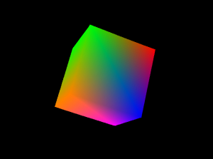
Figure 5-2. OpenGL graphics sample
First we write a new Activity, and in the onCreate() method we create the two fundamental objects we need to use the OpenGL API: a GLSurfaceView and a Renderer (see Example 5-3).
Example 5-3. OpenGL demo Activity
publicclassOpenGLDemoActivityextendsActivity{@OverridepublicvoidonCreate(BundlesavedInstanceState){super.onCreate(savedInstanceState);// Go fullscreenrequestWindowFeature(Window.FEATURE_NO_TITLE);getWindow().setFlags(WindowManager.LayoutParams.FLAG_FULLSCREEN,WindowManager.LayoutParams.FLAG_FULLSCREEN);GLSurfaceViewview=newGLSurfaceView(this);view.setRenderer(newOpenGLRenderer());setContentView(view);}}
Example 5-4 is the code for our Renderer; it uses a simple Cube object we’ll describe later to display a spinning cube.
Example 5-4. The renderer implementation
classOpenGLRendererimplementsRenderer{privateCubemCube=newCube();privatefloatmCubeRotation;@OverridepublicvoidonSurfaceCreated(GL10gl,EGLConfigconfig){gl.glClearColor(0.0f,0.0f,0.0f,0.5f);gl.glClearDepthf(1.0f);gl.glEnable(GL10.GL_DEPTH_TEST);gl.glDepthFunc(GL10.GL_LEQUAL);gl.glHint(GL10.GL_PERSPECTIVE_CORRECTION_HINT,GL10.GL_NICEST);}@OverridepublicvoidonDrawFrame(GL10gl){gl.glClear(GL10.GL_COLOR_BUFFER_BIT|GL10.GL_DEPTH_BUFFER_BIT);gl.glLoadIdentity();gl.glTranslatef(0.0f,0.0f,-10.0f);gl.glRotatef(mCubeRotation,1.0f,1.0f,1.0f);mCube.draw(gl);gl.glLoadIdentity();mCubeRotation-=0.15f;}@OverridepublicvoidonSurfaceChanged(GL10gl,intwidth,intheight){gl.glViewport(0,0,width,height);gl.glMatrixMode(GL10.GL_PROJECTION);gl.glLoadIdentity();GLU.gluPerspective(gl,45.0f,(float)width/(float)height,0.1f,100.0f);gl.glViewport(0,0,width,height);gl.glMatrixMode(GL10.GL_MODELVIEW);gl.glLoadIdentity();}}
Our onSurfaceChanged() and onDrawFrame() methods are basically the equivalent of the GLUT glutReshapeFunc() and glutDisplayFunc(). The first is called when the surface is resized—for instance, when the phone switches between landscape and portrait modes. The second is called at every frame, and that’s where we put the code to draw our cube (see Example 5-5).
Example 5-5. The Cube class
classCube{privateFloatBuffermVertexBuffer;privateFloatBuffermColorBuffer;privateByteBuffermIndexBuffer;privatefloatvertices[]={-1.0f,-1.0f,-1.0f,1.0f,-1.0f,-1.0f,1.0f,1.0f,-1.0f,-1.0f,1.0f,-1.0f,-1.0f,-1.0f,1.0f,1.0f,-1.0f,1.0f,1.0f,1.0f,1.0f,-1.0f,1.0f,1.0f};privatefloatcolors[]={0.0f,1.0f,0.0f,1.0f,0.0f,1.0f,0.0f,1.0f,1.0f,0.5f,0.0f,1.0f,1.0f,0.5f,0.0f,1.0f,1.0f,0.0f,0.0f,1.0f,1.0f,0.0f,0.0f,1.0f,0.0f,0.0f,1.0f,1.0f,1.0f,0.0f,1.0f,1.0f};privatebyteindices[]={0,4,5,0,5,1,1,5,6,1,6,2,2,6,7,2,7,3,3,7,4,3,4,0,4,7,6,4,6,5,3,0,1,3,1,2};publicCube(){ByteBufferbyteBuf=ByteBuffer.allocateDirect(vertices.length*4);byteBuf.order(ByteOrder.nativeOrder());mVertexBuffer=byteBuf.asFloatBuffer();mVertexBuffer.put(vertices);mVertexBuffer.position(0);byteBuf=ByteBuffer.allocateDirect(colors.length*4);byteBuf.order(ByteOrder.nativeOrder());mColorBuffer=byteBuf.asFloatBuffer();mColorBuffer.put(colors);mColorBuffer.position(0);mIndexBuffer=ByteBuffer.allocateDirect(indices.length);mIndexBuffer.put(indices);mIndexBuffer.position(0);}publicvoiddraw(GL10gl){gl.glFrontFace(GL10.GL_CW);gl.glVertexPointer(3,GL10.GL_FLOAT,0,mVertexBuffer);gl.glColorPointer(4,GL10.GL_FLOAT,0,mColorBuffer);gl.glEnableClientState(GL10.GL_VERTEX_ARRAY);gl.glEnableClientState(GL10.GL_COLOR_ARRAY);gl.glDrawElements(GL10.GL_TRIANGLES,36,GL10.GL_UNSIGNED_BYTE,mIndexBuffer);gl.glDisableClientState(GL10.GL_VERTEX_ARRAY);gl.glDisableClientState(GL10.GL_COLOR_ARRAY);}}
The Cube uses two FloatBuffer objects to store vertex and color information and a ByteBuffer to store the face indexes. In order for the buffers to work it is important to set their order according to the endianness of the platform, using the order() method. Once the buffers have been filled with the values from the arrays, the internal cursor must be restored to the beginning of the data using buffer.position(0).
See Also
5.3 Adding Controls to the OpenGL Spinning Cube
Marco Dinacci
Discussion
This recipe builds on Recipe 5.2 to show how to control the cube using a D-pad. We’re going to increment the speed rotation along the x-axis and y-axis using the D-pad’s directional keys.
The biggest change from that recipe is that we now have our custom class that extends the SurfaceView. We do this so that we can override the onKeyUp() method and be notified when the user uses the D-pad.
The onCreate() method of our Activity looks like Example 5-6.
Example 5-6. The spinning cube Activity
publicclassSpinningCubeActivity2extendsActivity{@OverridepublicvoidonCreate(BundlesavedInstanceState){super.onCreate(savedInstanceState);// go fullscreenrequestWindowFeature(Window.FEATURE_NO_TITLE);getWindow().setFlags(WindowManager.LayoutParams.FLAG_FULLSCREEN,WindowManager.LayoutParams.FLAG_FULLSCREEN);// create our custom viewGLSurfaceViewview=newOpenGLSurfaceView(this);view.setRenderer((Renderer)view);setContentView(view);}}
Our new GLSurfaceView also implements the Renderer interface. The onSurfaceCreated() and onSurfaceChanged() methods are exactly the same as in Recipe 5.2; most of the changes occur in onDrawFrame() as we introduce four new parameters: mXrot and mYrot to control the rotation of the cube along the x-axis and y-axis, and mXspeed and mYSpeed to store the speed of the rotation along the x-axis and y-axis. Each time the user clicks a D-pad button we alter the speed of the cube by modifying these parameters.
Example 5-7 shows the full code of our new class.
Example 5-7. The GLSurfaceView implementation
classOpenGLSurfaceViewextendsGLSurfaceViewimplementsRenderer{privateCubemCube;privatefloatmXrot;privatefloatmYrot;privatefloatmXspeed;privatefloatmYspeed;publicOpenGLSurfaceView(Contextcontext){super(context);// give focus to the GLSurfaceViewrequestFocus();setFocusableInTouchMode(true);mCube=newCube();}@OverridepublicvoidonDrawFrame(GL10gl){gl.glClear(GL10.GL_COLOR_BUFFER_BIT|GL10.GL_DEPTH_BUFFER_BIT);gl.glLoadIdentity();gl.glTranslatef(0.0f,0.0f,-10.0f);gl.glRotatef(mXrot,1.0f,0.0f,0.0f);gl.glRotatef(mYrot,0.0f,1.0f,0.0f);mCube.draw(gl);gl.glLoadIdentity();mXrot+=mXspeed;mYrot+=mYspeed;}@OverridepublicbooleanonKeyUp(intkeyCode,KeyEventevent){if(keyCode==KeyEvent.KEYCODE_DPAD_LEFT)mYspeed-=0.1f;elseif(keyCode==KeyEvent.KEYCODE_DPAD_RIGHT)mYspeed+=0.1f;elseif(keyCode==KeyEvent.KEYCODE_DPAD_UP)mXspeed-=0.1f;elseif(keyCode==KeyEvent.KEYCODE_DPAD_DOWN)mXspeed+=0.1f;returntrue;}// unchanged@OverridepublicvoidonSurfaceCreated(GL10gl,EGLConfigconfig){gl.glClearColor(0.0f,0.0f,0.0f,0.5f);gl.glClearDepthf(1.0f);gl.glEnable(GL10.GL_DEPTH_TEST);gl.glDepthFunc(GL10.GL_LEQUAL);gl.glHint(GL10.GL_PERSPECTIVE_CORRECTION_HINT,GL10.GL_NICEST);}// unchanged@OverridepublicvoidonSurfaceChanged(GL10gl,intwidth,intheight){gl.glViewport(0,0,width,height);gl.glMatrixMode(GL10.GL_PROJECTION);gl.glLoadIdentity();GLU.gluPerspective(gl,45.0f,(float)width/(float)height,0.1f,100.0f);gl.glViewport(0,0,width,height);gl.glMatrixMode(GL10.GL_MODELVIEW);gl.glLoadIdentity();}}
The Cube is inherited from Recipe 5.2. Don’t forget to call requestFocus() and setFocusableInTouchMode(true) in the constructor of the view, or else the key events will not be received.
See Also
Source Download URL
The source code for this example is in the Android Cookbook repository, in the subdirectory SpinningCubeDemo (see “Getting and Using the Code Examples”).
5.4 Freehand Drawing Smooth Curves
Ian Darwin
Discussion
This code was originally written by Eric Burke of Square Inc., for signatures when people use the Square app to capture credit card purchases. To be legally acceptable as proof of purchase, the captured signatures have to be of good quality. Square has graciously placed this code under the Apache Software License 2.0, but was not able to provide a description of it as part of this recipe.
I have since adapted the signature code for use in JabaGator, my very simple, general-purpose drawing program for the Java desktop and for Android (the fact that the name rhymes with a well-known illustration program from Adobe is, of course, purely coincidental).
Eric’s initial “by the book” drawing code worked but was very jerky and very slow. Upon investigation, Square learned that Android’s graphics layer sends touch events in “batches” when it cannot deliver them quickly enough individually. Each MotionEvent delivered to onTouchEvent() may contain a number of touch coordinates—as many as were captured since the last onTouchEvent() call. To draw a smooth curve, you must get all of the points. You do this using the number of coordinates from the TouchEvent method getHistorySize(), iterating over that count and calling getHistoricalX(int) and getHistoricalY(int) to get the point locations (see Example 5-8).
Example 5-8. Drawing all the points
// in onTouchEvent(TouchEvent):for(inti=0;i<event.getHistorySize();i++){floathistoricalX=event.getHistoricalX(i);floathistoricalY=event.getHistoricalY(i);// add point (historicalX, historicalY) to your path...}// add point (eventX, eventY) to your path...
This provides significant improvements, but it still is too slow for people to draw with—many nongeeks will wait for the drawing code to catch up with their finger if it doesn’t draw quickly enough! The problem is that this simple solution calls invalidate() after each line segment, which is correct but very slow as it forces Android to redraw the entire screen. The solution to this problem is to call invalidate() with just the region that you drew the line segment into, and it involves a bit of arithmetic to get the region correct; see the expandDirtyRect() method in Example 5-9. Here’s Eric’s description of the dirty-region algorithm:
Create a rectangle representing the dirty region.
Set the points for the four corners to the +X+ and +Y+ coordinates from the
ACTION_DOWNevent.For
ACTION_MOVEandACTION_UP, expand the rectangle to encompass the new points. (Don’t forget the historical coordinates!)Pass just the dirty rectangle to
invalidate(). Android won’t redraw the rest.
This set of steps makes the drawing code responsive and the application usable.
Example 5-9 shows my version of the final code. I have several OnTouchListeners: one for drawing curves, one for selecting objects, one for drawing rectangles, and so on. That code is not complete at present, but the curve-drawing part works nicely.
Example 5-9. DrawingView.java
// This code is dual-licensed under Creative Commons and Apache Software License 2.0publicclassDrawingViewextendsView{privatestaticfinalfloatSTROKE_WIDTH=5f;/** Need to track this so the dirty region can accommodate the stroke. **/privatestaticfinalfloatHALF_STROKE_WIDTH=STROKE_WIDTH/2;privatePaintpaint=newPaint();privatePathpath=newPath();/*** Optimizes painting by invalidating the smallest possible area.*/privatefloatlastTouchX;privatefloatlastTouchY;privatefinalRectFdirtyRect=newRectF();finalOnTouchListenerselectionAndMoveListener=// not shown;finalOnTouchListenerdrawRectangleListener=// not shown;finalOnTouchListenerdrawOvalListener=// not shown;finalOnTouchListenerdrawPolyLineListener=newOnTouchListener(){@OverridepublicbooleanonTouch(Viewv,MotionEventevent){// Log.d("jabagator", "onTouch: " + event);floateventX=event.getX();floateventY=event.getY();switch(event.getAction()){caseMotionEvent.ACTION_DOWN:path.moveTo(eventX,eventY);lastTouchX=eventX;lastTouchY=eventY;// No end point yet, so don't waste cycles invalidating.returntrue;caseMotionEvent.ACTION_MOVE:caseMotionEvent.ACTION_UP:// Start tracking the dirty region.resetDirtyRect(eventX,eventY);// When the hardware tracks events faster than// they can be delivered to the app, the// event will contain a history of those skipped points.inthistorySize=event.getHistorySize();for(inti=0;i<historySize;i++){floathistoricalX=event.getHistoricalX(i);floathistoricalY=event.getHistoricalY(i);expandDirtyRect(historicalX,historicalY);path.lineTo(historicalX,historicalY);}// After replaying history, connect the line to the touch point.path.lineTo(eventX,eventY);break;default:Log.d("jabagator","Unknown touch event "+event.toString());returnfalse;}// Include half the stroke width to avoid clipping.invalidate((int)(dirtyRect.left-HALF_STROKE_WIDTH),(int)(dirtyRect.top-HALF_STROKE_WIDTH),(int)(dirtyRect.right+HALF_STROKE_WIDTH),(int)(dirtyRect.bottom+HALF_STROKE_WIDTH));lastTouchX=eventX;lastTouchY=eventY;returntrue;}/*** Called when replaying history to ensure the dirty region* includes all points.*/privatevoidexpandDirtyRect(floathistoricalX,floathistoricalY){if(historicalX<dirtyRect.left){dirtyRect.left=historicalX;}elseif(historicalX>dirtyRect.right){dirtyRect.right=historicalX;}if(historicalY<dirtyRect.top){dirtyRect.top=historicalY;}elseif(historicalY>dirtyRect.bottom){dirtyRect.bottom=historicalY;}}/*** Resets the dirty region when the motion event occurs.*/privatevoidresetDirtyRect(floateventX,floateventY){// The lastTouchX and lastTouchY were set when the ACTION_DOWN// motion event occurred.dirtyRect.left=Math.min(lastTouchX,eventX);dirtyRect.right=Math.max(lastTouchX,eventX);dirtyRect.top=Math.min(lastTouchY,eventY);dirtyRect.bottom=Math.max(lastTouchY,eventY);}};/** DrawingView constructor */publicDrawingView(Contextcontext,AttributeSetattrs){super(context,attrs);paint.setAntiAlias(true);paint.setColor(Color.WHITE);paint.setStyle(Paint.Style.STROKE);paint.setStrokeJoin(Paint.Join.ROUND);paint.setStrokeWidth(STROKE_WIDTH);setMode(MotionMode.DRAW_POLY);}publicvoidclear(){path.reset();// Repaints the entire view.invalidate();}@OverrideprotectedvoidonDraw(Canvascanvas){canvas.drawPath(path,paint);}/*** Sets the DrawingView into one of several modes, such* as "select" mode (e.g., for moving or resizing objects),* or "draw polyline" (smooth curve), "draw rectangle", etc.*/privatevoidsetMode(MotionModemotionMode){switch(motionMode){caseSELECT_AND_MOVE:setOnTouchListener(selectionAndMoveListener);break;caseDRAW_POLY:setOnTouchListener(drawPolyLineListener);break;caseDRAW_RECTANGLE:setOnTouchListener(drawRectangleListener);break;caseDRAW_OVAL:setOnTouchListener(drawOvalListener);break;default:thrownewIllegalStateException("Unknown MotionMode "+motionMode);}}}
Figure 5-3 shows JabaGator running, showing my attempt at legible handwriting (don’t worry, that’s not my legal signature).

Figure 5-3. Touch drawing sample
This gives good drawing performance and smooth curves. The code to capture the curves into the drawing data model is not shown as it is application-specific.
See Also
You can find the original code and Eric’s description on the Square Corner blog.
Source Download URL
You can download the source code for this example from https://github.com/IanDarwin/jabagator.android/.
5.5 Taking a Picture Using an Intent
Ian Darwin
Solution
Create an Intent for MediaStore.ACTION_IMAGE_CAPTURE, tailor it a little, and call startActivityForResult on this Intent. Provide an onActivityResult() callback to get notified when the user is done with the camera.
Discussion
Example 5-10 shows code excerpted from the camera Activity in my JPSTrack application. Assuming that you want to save the image with your application’s data (instead of in the Media Gallery location), you want to provide a file-based URI referring to the target location, using intent.putExtra(MediaStore.EXTRA_OUTPUT, uri). Note that the Intent handler may give different results on different vendors’ platforms.
Example 5-10. The camera capture Activity
publicclassMainActivityextendsActivity{privatestaticfinalStringTAG="CameraLaunchingActivity";privatefinalstaticintACTION_TAKE_PICTURE=123;privateFilepictureFile;@OverrideprotectedvoidonCreate(BundlesavedInstanceState){super.onCreate(savedInstanceState);setContentView(R.layout.activity_main);}publicvoidtakePicture(Viewv){Log.d(TAG,"Starting Camera Activity");try{// Use an Intent to get the Camera app going.IntentimageIntent=newIntent(MediaStore.ACTION_IMAGE_CAPTURE);// Set up file to save image into.FilebaseDir=Environment.getExternalStoragePublicDirectory(Environment.DIRECTORY_PICTURES);FilepictureFile=newFile(baseDir,"picture1234.jpg");imageIntent.putExtra(MediaStore.EXTRA_VIDEO_QUALITY,1);imageIntent.putExtra(MediaStore.EXTRA_OUTPUT,Uri.fromFile(pictureFile));// And away we go!startActivityForResult(imageIntent,ACTION_TAKE_PICTURE);}catch(Exceptione){Toast.makeText(this,getString(R.string.cant_start_activity)+": "+e,Toast.LENGTH_LONG).show();}}/** Called when an Activity we started for Result is complete */@OverrideprotectedvoidonActivityResult(intrequestCode,intresultCode,Intentdata){switch(requestCode){caseACTION_TAKE_PICTURE:switch(resultCode){caseActivity.RESULT_OK:if(pictureFile.exists()){finalStringmessage=getString(R.string.picture_saved)+" "+pictureFile.getAbsoluteFile();Log.d(TAG,message);Toast.makeText(this,message,Toast.LENGTH_LONG).show();}else{finalStringmessage=getString(R.string.picture_created_but_missing);Toast.makeText(this,message,Toast.LENGTH_LONG).show();}break;caseActivity.RESULT_CANCELED:Toast.makeText(this,"Done",Toast.LENGTH_LONG).show();break;default:Toast.makeText(this,"Unexpected resultCode: "+resultCode,Toast.LENGTH_LONG).show();break;}break;default:Toast.makeText(this,"Unexpected requestCode: "+requestCode,Toast.LENGTH_LONG).show();}}}
Note
This code will fail if you set the target API to 24 or higher, since API 24 enforces
a restriction on exporting URIs to another application via ClipData (the theory being
that the other app might not have READ_EXTERNAL_STORAGE data).
It is recommended to use a content:// URI, which requires either a content provider (Recipe 10.15)
or a file provider (Recipe 10.19), both of which are sort of overkill for this project.
See Also
Source Download URL
The source code for this project is in the Android Cookbook repository, in the subdirectory CameraIntent (see “Getting and Using the Code Examples”).
5.6 Taking a Picture Using android.media.Camera
Marco Dinacci
Solution
Create a SurfaceView and implement the callbacks fired when the user takes a picture in order to have control over the image capture process.
Discussion
Sometimes you may want more control over the stages involved when taking a picture, or you may want to access and modify the raw image data acquired by the camera. In these cases, using a simple Intent to take a picture is not enough.
We’re going to create a new Activity and customize the view to make it full-screen inside the onCreate() method (Example 5-11).
Example 5-11. The take picture Activity
publicclassTakePictureActivityextendsActivity{privatePreviewmCameraView;@OverridepublicvoidonCreate(BundlesavedInstanceState){super.onCreate(savedInstanceState);// Force screen to landscape mode as showing a video in// portrait mode is not easily doable on all devicessetRequestedOrientation(ActivityInfo.SCREEN_ORIENTATION_LANDSCAPE);// Hide window title and go fullscreenrequestWindowFeature(Window.FEATURE_NO_TITLE);getWindow().addFlags(WindowManager.LayoutParams.FLAG_FULLSCREEN);mCameraView=newPreview(this);setContentView(mCameraView);}}
The Preview class is the bulk of the recipe. It handles the Surface where the pixels are drawn, and the Camera object.
We define a ClickListener in the constructor so that the user can take a picture by just tapping once on the screen. Once we get the notification of the click, we take a picture, passing as parameters four (all optional) callbacks (see Example 5-12).
Example 5-12. The SurfaceView implementation
classPreviewextendsSurfaceViewimplementsSurfaceHolder.Callback,PictureCallback{privateSurfaceHoldermHolder;privateCameramCamera;privateRawCallbackmRawCallback;publicPreview(Contextcontext){super(context);mHolder=getHolder();mHolder.addCallback(this);mHolder.setType(SurfaceHolder.SURFACE_TYPE_PUSH_BUFFERS);mRawCallback=newRawCallback();setOnClickListener(newOnClickListener(){@OverridepublicvoidonClick(Viewv){mCamera.takePicture(mRawCallback,mRawCallback,null,Preview.this);}});}
The Preview class implements the SurfaceHolder.Callback interface in order to be notified when the underlying surface is created, changed, and destroyed. We’ll use these callbacks to properly handle the Camera object (see Example 5-13).
Example 5-13. The surfaceChanged() method
@OverridepublicvoidsurfaceChanged(SurfaceHolderholder,intformat,intwidth,intheight){Camera.Parametersparameters=mCamera.getParameters();parameters.setPreviewSize(width,height);mCamera.setParameters(parameters);mCamera.startPreview();}@OverridepublicvoidsurfaceCreated(SurfaceHolderholder){mCamera=Camera.open();configure(mCamera);try{mCamera.setPreviewDisplay(holder);}catch(IOExceptionexception){closeCamera();}}@OverridepublicvoidsurfaceDestroyed(SurfaceHolderholder){closeCamera();}
As soon as the camera is created we call configure() in order to set the parameters the camera will use to take a picture—things like flash mode, effects, picture format, picture size, scene mode, and so on (Example 5-14). Since not all devices support all kinds of features, always ask which features are supported before setting them.
Example 5-14. The configure() method
privatevoidconfigure(Cameracamera){Camera.Parametersparams=camera.getParameters();// Configure image format. RGB_565 is the most common format.List<Integer>formats=params.getSupportedPictureFormats();if(formats.contains(PixelFormat.RGB_565))params.setPictureFormat(PixelFormat.RGB_565);elseparams.setPictureFormat(PixelFormat.JPEG);// Choose the biggest picture size supported by the hardwareList<Size>sizes=params.getSupportedPictureSizes();Camera.Sizesize=sizes.get(sizes.size()-1);params.setPictureSize(size.width,size.height);List<String>flashModes=params.getSupportedFlashModes();if(flashModes.size()>0)params.setFlashMode(Camera.Parameters.FLASH_MODE_AUTO);// Action mode takes pictures of fast-moving objectsList<String>sceneModes=params.getSupportedSceneModes();if(sceneModes.contains(Camera.Parameters.SCENE_MODE_ACTION))params.setSceneMode(Camera.Parameters.SCENE_MODE_ACTION);elseparams.setSceneMode(Camera.Parameters.SCENE_MODE_AUTO);// If you choose FOCUS_MODE_AUTO remember to call autoFocus() on// the Camera object before taking a pictureparams.setFocusMode(Camera.Parameters.FOCUS_MODE_FIXED);camera.setParameters(params);}
When the surface is destroyed, we close the camera and free its resources (Example 5-15):
Example 5-15. The closeCamera() method
privatevoidcloseCamera(){if(mCamera!=null){mCamera.stopPreview();mCamera.release();mCamera=null;}}
The jpeg callback is the last one called; this is where we restart the preview and save the file on disk (Example 5-16):
Example 5-16. Restarting the preview
@OverridepublicvoidonPictureTaken(byte[]jpeg,Cameracamera){// Now that all callbacks have been called it is safe to resume previewmCamera.startPreview();saveFile(jpeg);}}
Finally, we implement the ShutterCallback and we again implement the PictureCallback to receive the uncompressed raw image data (see Example 5-17).
Example 5-17. The ShutterCallback implementation
classRawCallbackimplementsShutterCallback,PictureCallback{@OverridepublicvoidonShutter(){// Notify the user, normally with a sound, that the picture has// been taken}@OverridepublicvoidonPictureTaken(byte[]data,Cameracamera){// Manipulate uncompressed image data}}
See Also
5.7 Scanning a Barcode or QR Code with the Google ZXing Barcode Scanner
Daniel Fowler
Discussion
One of the great features of Android is how easy it is to tap into existing functionality. Scanning barcodes and QR codes is a good example. Google has a free scanning app that you can access via an Intent; thus, an app can easily add scanning functionality, opening up new interface, communication, and feature possibilities.
The program in this recipe is an example of how to access the Google barcode scanner via an Intent. First, make sure the Google barcode scanner is installed. In Figure 5-4
there are three buttons that let the user choose to scan either a QR code, a product barcode, or something else. There are two TextViews to display the type of barcode scanned and the data it contains. The layout is conventional, a vertical LinearLayout, so we don’t need to reproduce it here.
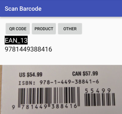
Figure 5-4. Barcode scanner application
The Activity code is shown in Example 5-18; depending on which button is pressed, the program puts the relevant parameters into the Intent before starting the ZXing Activity, and waits for the result.
Example 5-18. Scan program main Activity
publicclassMainActivityextendsAppCompatActivity{@OverrideprotectedvoidonCreate(BundlesavedInstanceState){super.onCreate(savedInstanceState);setContentView(R.layout.activity_main);}publicvoidHandleClick(Viewarg0){Intentintent=newIntent("com.google.zxing.client.android.SCAN");switch(arg0.getId()){caseR.id.butQR:intent.putExtra("SCAN_MODE","QR_CODE_MODE");break;caseR.id.butProd:intent.putExtra("SCAN_MODE","PRODUCT_MODE");break;caseR.id.butOther:intent.putExtra("SCAN_FORMATS","CODE_39,CODE_93,CODE_128,DATA_MATRIX,ITF,CODABAR");break;}try{startActivityForResult(intent,0);// Barcode scanner to scan for us}catch(ActivityNotFoundExceptione){Toast.makeText(this,"Please install the ZXing Barcode Scanner app",Toast.LENGTH_LONG).show();}}publicvoidonActivityResult(intrequestCode,intresultCode,Intentintent){if(requestCode==0){TextViewtvStatus=(TextView)findViewById(R.id.tvStatus);TextViewtvResult=(TextView)findViewById(R.id.tvResult);if(resultCode==RESULT_OK){tvStatus.setText(intent.getStringExtra("SCAN_RESULT_FORMAT"));tvResult.setText(intent.getStringExtra("SCAN_RESULT"));}elseif(resultCode==RESULT_CANCELED){tvStatus.setText("Press a button to start a scan.");tvResult.setText("Scan cancelled.");}}}}
Notice, in the table that follows, how it’s possible to scan for a family of barcodes (using SCAN_MODE) or for a specific type of barcode (using SCAN_FORMATS). If you know what type of barcode is being decoded, setting SCAN_FORMATS to that particular type may result in faster decoding (because the ZXing app won’t try to run through all the barcode decoding algorithms). For example, you could use intent.putExtra("SCAN_FORMATS", "CODE_39"). To use multiple formats, you’d pass a comma-separated list; refer back to Example 5-18.
SCAN_MODE |
SCAN_FORMATS |
|---|---|
|
|
|
|
|
|
|
|
|
|
|
|
|
As for |
|
|
|
|
|
|
|
|
|
|
|
|
|
|
Now go and make that scanning inventory control or grocery list app you’ve been thinking of!
See Also
XZing, the developer documentation on intents and intent filters.
Source Download URL
The source code for this example is in the Android Cookbook repository, in the subdirectory ScanBarcode (see “Getting and Using the Code Examples”).
5.8 Using AndroidPlot to Display Charts and Graphs
Rachee Singh
Discussion
You can either download the AndroidPlot library and add it
to your libs folder or,
preferably, add the coordinates com.androidplot:androidplot-core:jar:1.2.1 to your build scripts or add this
as a module dependency in Android Studio.
In our sample application, we are hardcoding some data and showing the plot corresponding to the data in the application. So, we need to add an (x,y) plot to our XML layout (main.xml). Example 5-19 shows what main.xml looks like with an XYPlot component in a linear layout.
Example 5-19. The XML layout with XYPlot
<?xml version="1.0" encoding="utf-8"?><LinearLayoutxmlns:android="http://schemas.android.com/apk/res/android"android:orientation="vertical"android:layout_width="fill_parent"android:layout_height="fill_parent"><com.androidplot.xy.XYPlotandroid:id="@+id/mySimpleXYPlot"android:layout_width="fill_parent"android:layout_height="wrap_content"title="Stats"/></LinearLayout>
Now, in the application code, get a reference to the XYPlot defined in the XML:
mySimpleXYPlot=(XYPlot)findViewById(R.id.mySimpleXYPlot);
Initialize two arrays of numbers for which the plot will be displayed:
// Create two arrays of y-values to plot:Number[]series1Numbers={1,8,5,2,7,4};Number[]series2Numbers={4,6,3,8,2,10};
Turn the arrays into XYSeries:
XYSeriesseries1=newSimpleXYSeries(// SimpleXYSeries takes a List, so turn our array into a ListArrays.asList(series1Numbers),// Y_VALS_ONLY means use the element index as the x-valueSimpleXYSeries.ArrayFormat.Y_VALS_ONLY,// Set the display title of the series"Series1");
Create a formatter to use for drawing a series using LineAndPointRenderer:
LineAndPointFormatterseries1Format=newLineAndPointFormatter(Color.rgb(0,200,0),// line colorColor.rgb(0,100,0),// point colorColor.rgb(150,190,150));// fill color (optional)
Add series1 and series2 to the XYPlot:
mySimpleXYPlot.addSeries(series1,series1Format);mySimpleXYPlot.addSeries(series2,newLineAndPointFormatter(Color.rgb(0,0,200),Color.rgb(0,0,100),Color.rgb(150,150,190)));
And make it look cleaner:
// Reduce the number of range labelsmySimpleXYPlot.setTicksPerRangeLabel(3);// By default, AndroidPlot displays developer guides to aid in laying out// your plot. To get rid of them call disableAllMarkup().mySimpleXYPlot.disableAllMarkup();mySimpleXYPlot.getBackgroundPaint().setAlpha(0);mySimpleXYPlot.getGraphWidget().getBackgroundPaint().setAlpha(0);mySimpleXYPlot.getGraphWidget().getGridBackgroundPaint().setAlpha(0);
Run the application! It should look like Figure 5-5.
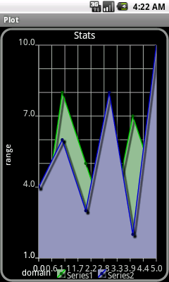
Figure 5-5. AndroidPlot display
Source Download URL
The source code for this project is in the Android Cookbook repository, in the subdirectory AndroidPlot (see “Getting and Using the Code Examples”).
5.9 Using Inkscape to Create an Android Launcher Icon from OpenClipArt.org
Daniel Fowler
Solution
Inkscape is a free and feature-rich graphics program that can export to a bitmap file; you can use it to create the variously sized icons needed for an app.
Discussion
You need a graphics program to design the graphical resources used in an Android application. Inkscape is a free, multiplatform graphics program with some very powerful features. You can use it to generate high-quality vector graphics that can then be exported to any required resolution. This is ideal for generating Android launcher icons (and other graphical resources). See the Inkscape website for more information on the program and to download the latest version.
The required sizes are described in “About Android Launcher Icons”. When designing an icon, it’s better to work with images that are larger than the required size. A larger image is easier to work with in a graphics program and easily scaled down when completed. An image that is 576×576 pixels is divisible equally by all the icon sizes, and this is a reasonable size in which to design. For a vector-based graphics package such as Inkscape, the image size is irrelevant; it can be scaled up and down without losing quality. Inkscape uses the open Scalable Vector Graphics (SVG) format. Image detail is only lost when the final bitmap images are produced from the vector image.
If you want to learn how to design images in Inkscape, you can use the many tutorials that are available both via the Help menu and online; the Inkscape Tutorials Blog is a good tutorial reference.
Once you have designed an image in Inkscape, you can export it to a PNG file for use as an app icon. In the following example, the image to be converted to icons came from the “Creating a Coffee Cup with Inkscape” tutorial. If you follow the tutorial, you’ll create the image shown in Figure 5-7.

Figure 5-7. A cup of java
If you don’t want to follow the tutorial, you can obtain a coffee cup image from Openclipart, a great source of free images (see Figure 5-8). Search for “coffee” and you’ll see various coffee-related images, including the one shown in Figure 5-7, uploaded by this recipe’s author. Select the image, click the View SVG button, and then use your browser’s File → Save menu to save the image.
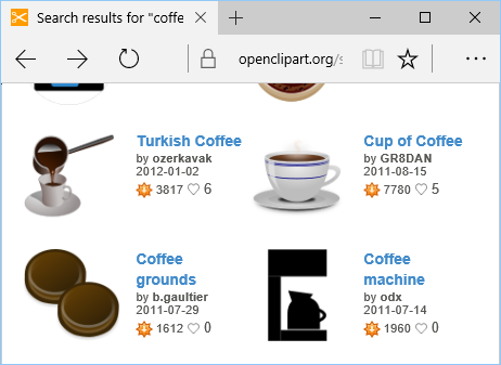
Figure 5-8. Searching for the perfect cup
You can now convert the image to an icon for whatever coffee-related app is currently in the pipeline. The required icon sizes are generated from the image using the Inkscape Export to PNG option. The image is opened and correctly proportioned for the export. This can be done for any image designed or opened in Inkscape. Remember that images should not be overly detailed or have too many colors (detail is reduced during resizing), and that they should try to fill (or fit) a square area. It’s worth reading the Android Design guidelines, including those on launcher icons.
With the image open, resize the document to 576×576 pixels. To do this, use the Document Properties option under the File menu (see Figure 5-9). In the “Custom size” section, set Width and Height to 576 and check that Units is set to “px” (for pixels). Also, make sure that the “Show page border” checkbox is ticked.
Close the Document Properties dialog, then drag two vertical and two horizontal guides from the rulers (click and drag from any part of the page ruler; if the rulers aren’t visible, use the View → Show/Hide → Rulers menu option to display them.) Drag the guides inside each page border approximately one-twelfth of the width and height of the visible page border. You’ll now set the accurate position of the guides using the guide properties. Double-click each guide and set the following positions:
| Guide | x | y |
|---|---|---|
Top horizontal |
0 |
528 |
Bottom horizontal |
0 |
48 |
Left vertical |
48 |
0 |
Right vertical |
528 |
0 |
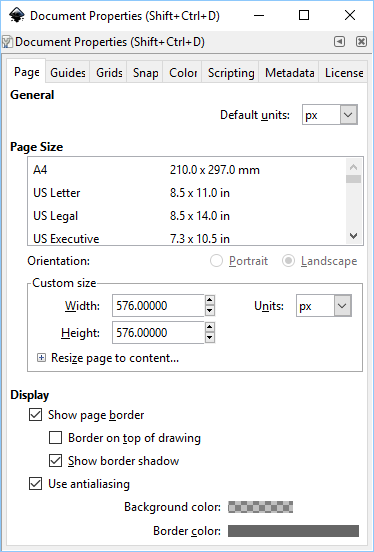
Figure 5-9. The Document Properties dialog
At this point, you should be able to easily adjust the image to fit within the guides. (Minor protrusions into the border area are allowed if required for image balance.) Use the Edit → Select All menu item or press Ctrl-A to select the image, drag the image into position, and then resize it as appropriate to fit within the box outlined by the guides (see Figure 5-10).
With the image created and correctly proportioned, you can now create the bitmaps for an Android project. In Inkscape, ensure that the image is not selected (click outside the image), and then use the File → Export PNG Image menu option to bring up the Export PNG Image dialog (see Figure 5-11). Select Page, then under “Image size” set Width and Height as per Table 5-1; you do not need to change the dpi setting (it will change as Width and Height are changed). Under Filename, browse to the project directory for the icon and enter ic_launcher.png for the filename. Finally, click the Export button to generate the icon. Repeat this process for all the icon resolutions.
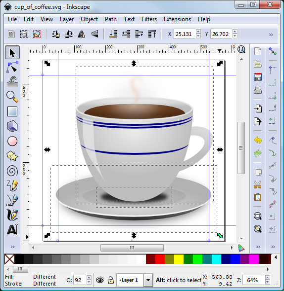
Figure 5-10. Resizing in Inkscape
You should test the application on physical and virtual devices to ensure that the icons display as expected (see Figure 5-12).
The icon files do not need to be called ic_launcher.png; see Recipe 5.10 for information on changing the launcher icon filename.
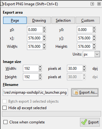
Figure 5-11. The Export PNG Image dialog
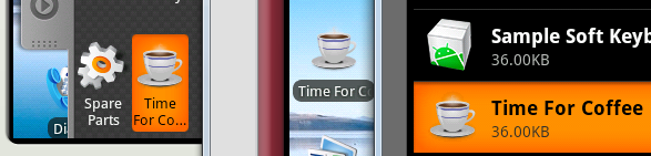
Figure 5-12. Icon in use
5.10 Using Paint.NET to Create Launcher Icons from OpenClipArt.org
Daniel Fowler
Solution
Openclipart.org is a good source of free graphics that you can adapt for use as an icon for your app. Paint.NET is a good application for generating launcher icons.
Discussion
Developers with access to a graphic artist, either professionally or through friends, or who are good artists themselves will have finer control over the graphics within their applications. However, many developers find creating the graphics in an app a chore. This recipe shows how to generate a good icon quickly, by compromising on the fine control provided by a dedicated artist.
Android Studio comes with the Image Asset utility, which is good for creating basic images at various densities, including launcher icons. To run the utility, with the app folder highlighted in Studio, use the File → New → Image Asset menu option. To use an existing clip art image as your starting point, click the tiny “Clip Art” icon in the left panel. In Figure 5-13 we have selected the Heart icon (about one-third of the way down in the All category), clicked OK, and changed the foreground and background colors.
For a more complex icon, a good source of free images is Openclipart. The graphics provided are in vector format, which makes them great for scaling to icon size. Icons are a raster format, so once a suitable graphic has been chosen it needs to be converted to the Android icon format, Portable Network Graphics (PNG).
For this recipe, we will add an icon to the example “Hello, World” app created in Recipe 1.15.
First, find a suitable free graphic as a starting point. Go to https://openclipart.org/ and use the Search box. The search results may include graphics that don’t seem logical. This is because the search not only includes the name of the graphic, but also tags and descriptions, as well as partial words; therefore, graphics unrelated to the major search term will appear, as will contributions with misspellings or whose names are in a different language. But this also means that you may find an unexpected but suitable graphic.
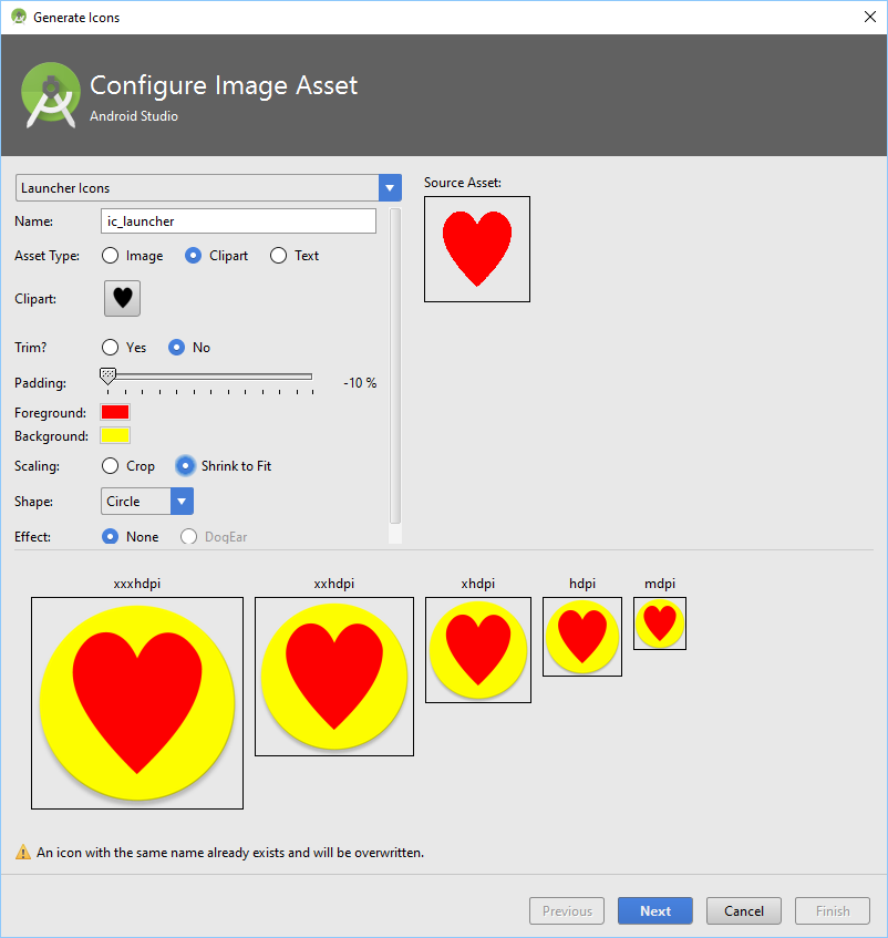
Figure 5-13. Studio Image Asset tool—Generate Icons
Page through the search results, which are provided as thumbnails with title, contributor name, date of submission, and number of downloads. When looking for a graphic to use as an icon, keep these pointers in mind:
-
Figure 5-14 shows the recommended color palette to fit in with the Android theme; this is only a recommendation, but it is a useful guide. Avoid any color that is too extreme.
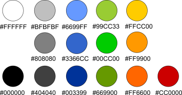
Figure 5-14. Color palette
-
The graphic will be scaled down dramatically, so avoid graphics with too much detail. The search result thumbnail itself is a good indicator.
-
Clear and simple designs with smooth lines and bright, neutral colors will scale well and look good on device screens.
-
Keep in mind the Android design guidelines on launcher icons; graphical representations should be face on (viewed straight on), with a small drop shadow and top lighting.
-
Icons are square, so look for an image that, if bounded by a square, would fill most of that square.
For the “Hello, World” app I used the search term earth (see Figure 5-15).
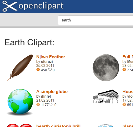
Figure 5-15. Clip art search results
I chose the graphic titled “A simple globe.” Click the graphic to bring up its details. You can save the graphic to the local machine by clicking it (or clicking the View SVG button) and using the browser’s File menu. However, using the browser’s File → Save menu option or typing Ctrl-S will save the file as a vector file, which, as discussed earlier, is not a good format for an icon. Fortunately, the image’s Openclipart page has an option to obtain the file as a PNG file; click the image you want, and the dialog in Figure 5-16 will appear.
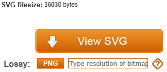
Figure 5-16. Convert to PNG with given size
On this page, we can use the PNG button to obtain PNG files in the image sizes required (refer back to “About Android Launcher Icons” for details on sizes). In the box next to the PNG button type in the first image size required, 30 (for the low-density icon; see Figure 5-16). We cannot put in the full icon size, 36, because that would not leave any border.
Click the PNG button and then use the browser’s File menu (or Ctrl-S) to save the generated PNG file. Then click the browser’s Back button. Clear the box next to the PNG button and enter the size of the next icon graphic required: in this case, 40 for the medium-density icon. Again click the PNG button and save the generated file. Do the same for all the other sizes. When you are done, you should have five or six files, each containing the same image at a different resolution (Figure 5-17). The graphics files may not be perfectly square—for example, they may be 39×40 instead of 40×40 pixels—but the small difference does not matter.

Figure 5-17. Icons of Earth in some of the required sizes
You now need to resize the files to the correct icon sizes by adding the empty border. You can do this in a graphics application such as GIMP, Inkscape, or Paint.NET (Windows only). For this recipe, we will use Paint.NET.
In Paint.NET, open the first graphics file. Set the secondary (background) color to transparent by selecting the Window menu option → Colors or pressing F8; in the Colors dialog, ensure that Secondary is selected in the drop-down, and then click the More button to see the advanced options. Set the Transparency option in the bottom right of the Colors dialog to zero (see Figure 5-18).

Figure 5-18. Color selection palette
Next, open the Canvas Size dialog by selecting the Image → Canvas Size menu option or pressing Ctrl-Shift-R. Select the “By absolute size” radio button, but ignore the “Maintain aspect ratio” checkbox (if the graphic is square, this checkbox can be checked, but if not it should be unchecked). In the “Pixel size” options, set the correct Width and Height for the icon for the given graphic—both 36 for the 30×30 graphic, both 48 for the 40×40 graphic, both 72 for the 60×60 graphic, and so on for the other sizes. Set the Anchor option to Middle. When you’re done, click OK (see Figure 5-19). Save the resized image and repeat for the remaining sizes.
With a project open in Android Studio, under the res folder there will exist some mipmap folders for the launcher icon (the older drawable folders are used for all graphics other than the launcher icons). Copy the new PNG files into the correct density folders as ic_launcher.png, creating the required folder under res if needed. Table 5-2 provides a summary.
| Folder | Icon size | Image size | dpi | Android density | Example screen | Notes |
|---|---|---|---|---|---|---|
mipmap-ldpi |
36×36 |
30×30 |
120 |
ldpi |
Small QVGA |
|
mipmap-mdpi |
48×48 |
40×40 |
160 |
mdpi |
Normal HVGA |
Default icon in absence of anything else |
mipmap-hdpi |
72×72 |
60×60 |
240 |
hdpi |
Normal WVGA800 |
|
mipmap-xhdpi |
96×96 |
80×80 |
320 |
xhdpi |
WXGA720 |
|
mipmap-xxhdpy |
144×144 |
120×120 |
160 |
xxdpi |
Nexus 5 |
|
mipmap-xxxhdpy |
192×192 |
160×160 |
160 |
xxxhdpi |
Nexus 6 |
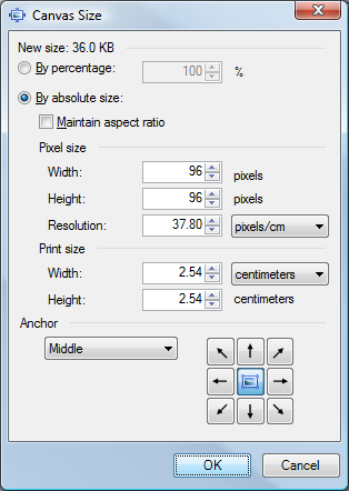
Figure 5-19. Setting canvas size
Figure 5-20 illustrates the effect of adding a border around the image by specifying the larger icon size; this allows for appropriate spacing between icons and accommodates any minor image protrusions.

Figure 5-20. An 80x80-pixel icon, with and without the recommended border
Note that QVGA stands for “Quarter VGA” (VGA was the “advanced” 640×480 video on a model of the original IBM PC in the last century), HVGA is Half VGA, and so on.
The AndroidManifest.xml file references the icon file via the application element’s android:icon attribute (here, android:icon="@mipmap/ic_launcher"). This is shown in Figure 5-21.
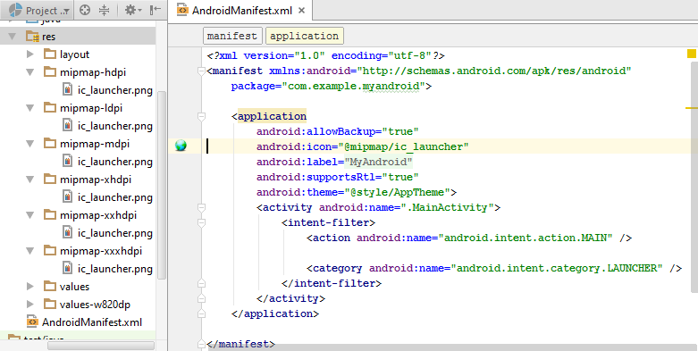
Figure 5-21. The icon file setting in the AndroidManifest.xml file
Note
The icon files do not need to be called ic_launcher.png. As long as all the filenames in all the resource folders are valid and the same, they can be named something else. For example, you might call these icon files globe.png. If you change the filename from the default, however, you will also need to change the value of the android:icon attribute in the application element in the manifest file (for example, from android:icon="@mipmap/ic_launcher" to android:icon="@mipmap/globe").
Now you should be all set—you should see icons in each of the mipmap subdirectories. Be sure to test the icons on various devices to make sure they look okay.
Remember to give thanks for free stuff; in this case I thank Open Clipart Library contributor jhnri4.
See Also
Recipe 1.15; Android design guidelines for icons, Openclipart, Paint.NET, Inkscape, GIMP.
5.11 Using Nine Patch Files
Daniel Fowler
Discussion
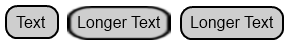
In the following picture, the word “Text” has a background that is a rounded rectangle (a black border with a gray background). The rectangle has then been uniformly scaled to fit “Longer Text.” As a result of the scaling, the corners and vertical edges have been distorted, giving the rounded rectangle an unbalanced look. Compare that to the second “Longer Text,” where the background has maintained its balance:
To correctly scale the background, selected parts of the image are scaled in a particular direction, or not scaled at all. Which parts are scaled and in which direction are shown in this diagram:

The Xs indicate that corners are not scaled, while the vertical edges are scaled vertically, the horizontal edges are scaled horizontally, and the central area is scaled in both directions. Hence the name NinePatch:
4 corners +
2 vertical edges +
2 horizontal edges +
1 central area
---------------------
9 areas (patches) in total
In the following example, the default black border and gray gradient background of an EditText is replaced with a solid turquoise background and a black border. The required rounded rectangle can be drawn in a graphics program such as GIMP or Paint.NET. The rectangle should be drawn as small as possible (resembling a circle) to support small views, with a 1-pixel border and a transparent background. I’ve also drawn a version of the rectangle with an orange border to support focus indication used with keypad navigation:

Android needs to know which proportions of the vertical and horizontal edges need to be scaled, as well as where the view content sits in relation to the background. These factors are determined from indicators drawn within the image. To apply these indicators, use the draw9patch program supplied with the Android SDK tools. Start the program and open the background image (drag and drop it onto the draw9patch dialog). The program will expand the image by one pixel all around, as per Figure 5-22. You’re going to draw indicator lines on this extra 1-pixel edging. Enlarge the image using the Zoom slider. In the lefthand and top edges, draw the indicator lines to mark which of the vertical and horizontal pixels can be duplicated for scaling. In the righthand and bottom edges, draw the indicator lines to show where content can be positioned.
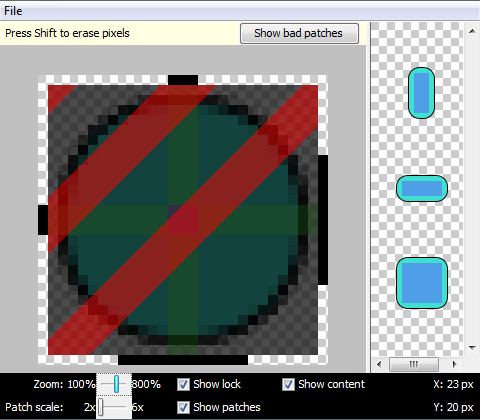
Figure 5-22. The draw9patch program in action
Figure 5-23 shows the right and bottom markers for content placement. If content does not fit in the indicated rectangle, the background image is stretched using the area shown by the left and top markers.
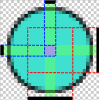
Figure 5-23. draw9patch: Markers for content placement
Save the marked-up file in the res/drawable folder for a project. Android determines whether an image is scaled using NinePatch scaling instead of uniform scaling via the filename; it must have .9 before the .png file extension. For example, an image file named turquoise.png would be named turquoise.9.png. To use the background image, reference it in a layout with android:background="@drawable/turquoise". If you are also using another image to indicate view focus, use a selector file—for example, save this XML file in the drawable folder as selector.xml:
<?xml version="1.0" encoding="utf-8"?><selectorxmlns:android="http://schemas.android.com/apk/res/android"><itemandroid:state_focused="true"android:drawable="@drawable/turqfocus"/><itemandroid:drawable="@drawable/turquoise"/></selector>
Then reference this as android:background="@drawable/selector". Figure 5-24 shows the results.
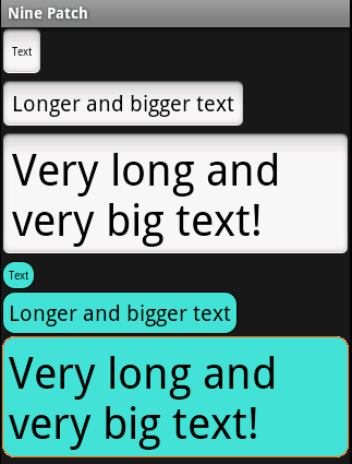
Figure 5-24. NinePatch file used as selector and background
Notice that the new view background is using a little less space than the default (this is useful to know if a project needs a little bit more screen area).
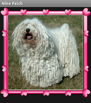
NinePatch files are not restricted to simple view backgrounds. This NinePatch file is used to frame a photograph:

Notice how the left and top scaling indicators are split where detail that must not be scaled (because it would distort) is located. Here’s the result:
See Also
The developer documentation on NinePatch.
5.12 Creating HTML5 Charts with Android RGraph
Wagied Davids
Solution
As an alternative to creating Android charts in pure Java, create charts using RGraph, an HTML5 JavaScript charts library.
Note
RGraph will not work on Android prior to 2.1, but that shouldn’t be a problem today.
Discussion
To create a chart with RGraph, follow these steps:
-
Create an assets directory for HTML files; Android internally maps it to file:///android_asset/ (note the triple slash and singular spelling of “asset”).
-
Copy rgraphview.html (see Example 5-20) into it: res/assets/rgraphview.html.
-
Create a JavaScript directory: res/assets/RGraph.
-
Create the layout (Example 5-21) and the Activity (Example 5-22) as in any other Android project.
Example 5-20 shows the HTML using the RGraph library. Figure 5-25 shows the RGraph output.
Example 5-20. HTML using the RGraph library
<html><head><title>RGraph: HTML5 canvas graph library - pie chart</title><scriptsrc="RGraph/libraries/RGraph.common.core.js"></script><scriptsrc="RGraph/libraries/RGraph.common.annotate.js"></script><scriptsrc="RGraph/libraries/RGraph.common.context.js"></script><scriptsrc="RGraph/libraries/RGraph.common.tooltips.js"></script><scriptsrc="RGraph/libraries/RGraph.common.zoom.js"></script><scriptsrc="RGraph/libraries/RGraph.common.resizing.js"></script><scriptsrc="RGraph/libraries/RGraph.pie.js"></script><script>window.onload=function(){/*** These are not angles - these are values.* The appropriate angles are calculated.*/varpie1=newRGraph.Pie('pie1',[41,37,16,3,3]);// Create pie objectpie1.Set('chart.labels',['MSIE 7 (41%)','MSIE 6 (37%)','Firefox (16%)','Safari (3%)','Other (3%)']);pie1.Set('chart.gutter',30);pie1.Set('chart.title',"Browsers (tooltips, context, zoom)");pie1.Set('chart.shadow',false);pie1.Set('chart.tooltips.effect','contract');pie1.Set('chart.tooltips',['Internet Explorer 7 (41%)','Internet Explorer 6 (37%)','Mozilla Firefox (16%)','Apple Safari (3%)','Other (3%)']);pie1.Set('chart.highlight.style','3d');// 2d or 3d; defaults to 3dif(!RGraph.isIE8()){pie1.Set('chart.zoom.hdir','center');pie1.Set('chart.zoom.vdir','up');pie1.Set('chart.labels.sticks',true);pie1.Set('chart.labels.sticks.color','#aaa');pie1.Set('chart.contextmenu',[['Zoom in',RGraph.Zoom]]);}pie1.Set('chart.linewidth',5);pie1.Set('chart.labels.sticks',true);pie1.Set('chart.strokestyle','white');pie1.Draw();varpie2=newRGraph.Pie('pie2',[2,29,45,17,7]);// Create pie objectpie2.Set('chart.gutter',45);pie2.Set('chart.title',"Some data (context, annotatable)");pie2.Set('chart.linewidth',1);pie2.Set('chart.strokestyle','#333');pie2.Set('chart.shadow',true);pie2.Set('chart.shadow.blur',3);pie2.Set('chart.shadow.offsetx',3);pie2.Set('chart.shadow.offsety',3);pie2.Set('chart.shadow.color','rgba(0,0,0,0.5)');pie2.Set('chart.colors',['red','pink','#6f6','blue','yellow']);pie2.Set('chart.contextmenu',[['Clear',function(){RGraph.Clear(pie2.canvas);pie2.Draw();}]]);pie2.Set('chart.key',['John (2%)','Richard (29%)','Fred (45%)','Brian (17%)','Peter (7%)']);pie2.Set('chart.key.background','white');pie2.Set('chart.key.shadow',true);pie2.Set('chart.annotatable',true);pie2.Set('chart.align','left');pie2.Draw();}</script></head><body><divstyle="text-align: center"><canvasid="pie1"width="420"height="300">[No canvas support]</canvas><canvasid="pie2"width="440"height="300">[No canvas support]</canvas></div></body></html>

Figure 5-25. RGraph output
Example 5-21. The main.xml file
<?xml version="1.0" encoding="utf-8"?><LinearLayoutxmlns:android="http://schemas.android.com/apk/res/android"android:orientation="horizontal"android:layout_width="fill_parent"android:layout_height="fill_parent"android:background="#FFFFFF"><WebViewandroid:id="@+id/webview"android:layout_width="fill_parent"android:layout_height="fill_parent"></WebView></LinearLayout>
Example 5-22. The main Activity
importandroid.app.Activity;importandroid.os.Bundle;importandroid.webkit.WebChromeClient;importandroid.webkit.WebSettings;importandroid.webkit.WebView;importandroid.webkit.WebViewClient;publicclassMainextendsActivity{/** Called when the Activity is first created. */@OverridepublicvoidonCreate(BundlesavedInstanceState){super.onCreate(savedInstanceState);setContentView(R.layout.main);// Obtain reference to the WebView holderWebViewwebview=(WebView)this.findViewById(R.id.webview);// Get the settingsWebSettingswebSettings=webview.getSettings();// Enable JavaScript for user interaction clickswebSettings.setJavaScriptEnabled(true);// Display zoom controlswebSettings.setBuiltInZoomControls(true);webview.requestFocusFromTouch();// Set the clientwebview.setWebViewClient(newWebViewClient());webview.setWebChromeClient(newWebChromeClient());// Load the URLwebview.loadUrl("file:///android_asset/rgraphview.html");}}
Source Download URL
The source code for this example is in the Android Cookbook repository, in the subdirectory RGraphDemo (see “Getting and Using the Code Examples”).
5.13 Adding a Simple Raster Animation
Daniel Fowler
Solution
Android has good support for user interface animation; it is easy to sequence images using the AnimationDrawable class.
Discussion
To create the animation, first generate the images to be sequenced, using a graphics program. Each image represents one frame of the animation; the images will usually be the same size, with changes between each frame as required.
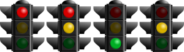
This animation recipe will sequence some traffic light images. The images can be generated using the open source vector graphics program Inkscape. A copy of the image used is available from the Open clipart library; search for “traffic lights turned off,” select the image, click the View SVG button, and save the file from your browser. Then open the file in Inkscape.
The animation will comprise four images showing the sequence of traffic lights as used in the United Kingdom: red, red and yellow, green, yellow, and back to red. The SVG image has all the lights available—they are just hidden behind translucent circles. To generate the first image, select the circle covering the red light and delete it. Then use the Edit → Select All menu option to highlight the whole image. Select Export to PNG from the File menu. In the Export to PNG dialog, under “Bitmap size,” enter 150 in the Height box, and choose a directory and filename for the file to be generated—for example, red.png (see Figure 5-26).
Click the Export button to export the bitmap. Delete the circle covering the yellow light, click Edit → Select All again, and export as before to a file; for example, red_yellow.png. Use the Edit → Undo menu option (twice) to cover the red light and yellow light, and then delete the circle covering the green light. Export to green.png. Again use Undo to cover the green light, and delete the circle covering the yellow light. Export the bitmap to yellow.png.
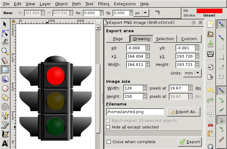
Figure 5-26. The Export to PNG dialog
The files are now ready for the animation:
Start an Android project. Copy the four generated files into the res/drawable directory. An animation-list needs to be defined in the same directory. Create a new file in res/drawable called uktrafficlights.xml. In this new file, add the following:
<?xml version="1.0" encoding="utf-8"?><animation-listxmlns:android="http://schemas.android.com/apk/res/android"android:oneshot="false"><itemandroid:drawable="@drawable/red"android:duration="2000"/><itemandroid:drawable="@drawable/red_yellow"android:duration="2000"/><itemandroid:drawable="@drawable/green"android:duration="2000"/><itemandroid:drawable="@drawable/yellow"android:duration="2000"/></animation-list>
This lists the images to be animated in the order of the animation and how long each one needs to be displayed (in milliseconds). If the animation needs to stop after running through the images, set the attribute android:oneshot to true.
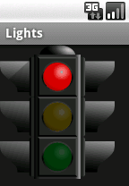
In the layout file for the program, add an ImageView whose source is given as @drawable/uktrafficlights (i.e., pointing to the created file):
<?xml version="1.0" encoding="utf-8"?><LinearLayoutxmlns:android="http://schemas.android.com/apk/res/android"android:orientation="vertical"android:layout_width="fill_parent"android:layout_height="fill_parent"><ImageViewandroid:id="@+id/imageView1"android:src="@drawable/uktrafficlights"android:layout_height="wrap_content"android:layout_width="wrap_content"/></LinearLayout>
In the Activity class, create an instance of AnimationDrawable (the Android class that performs the animation) called lightsAnimation. In onCreate(), assign it to the Drawable that the ImageView uses. Finally, start the animation by calling the AnimationDrawable start() method (there is a stop() method available to end the animation if required). We do this in onWindowFocusChanged to ensure that everything has loaded before the animation starts (it could easily have been started with a button or other type of input). Example 5-23 shows the code for the main Activity.
Example 5-23. The main Activity
publicclassmainextendsActivity{AnimationDrawablelightsAnimation;@OverridepublicvoidonCreate(BundlesavedInstanceState){super.onCreate(savedInstanceState);setContentView(R.layout.main);ImageViewlights=(ImageView)findViewById(R.id.imageView1);lightsAnimation=(AnimationDrawable)lights.getDrawable();}@OverridepublicvoidonWindowFocusChanged(booleanhasFocus){super.onWindowFocusChanged(hasFocus);lightsAnimation.start();}}
Image animations can be useful to add interest to screens and can be used in games or cartoons.
See Also
5.14 Using Pinch to Zoom
Pratik Rupwal
Solution
Scale the image as a matrix to apply transformations to it, to show different visual effects.
Discussion
First, add a simple ImageView inside a FrameLayout in main.xml, as shown here:
<?xml version="1.0" encoding="utf-8"?><FrameLayoutxmlns:android="http://schemas.android.com/apk/res/android"android:layout_width="fill_parent"android:layout_height="fill_parent"><ImageViewandroid:id="@+id/imageView"android:layout_width="fill_parent"android:layout_height="fill_parent"android:src="@drawable/nature"android:scaleType="matrix"></ImageView></FrameLayout>
Example 5-24 scales the ImageView as a matrix to apply transformations on it.
Example 5-24. Touch listener with scaling
publicclassTouchextendsActivityimplementsOnTouchListener{privatestaticfinalStringTAG="Touch";// These matrixes will be used to move and zoom imageMatrixmatrix=newMatrix();MatrixsavedMatrix=newMatrix();// We can be in one of these 3 statesstaticfinalintNONE=0;staticfinalintDRAG=1;staticfinalintZOOM=2;intmode=NONE;// Remember some things for zoomingPointFstart=newPointF();PointFmid=newPointF();floatoldDist=1f;@OverridepublicvoidonCreate(BundlesavedInstanceState){super.onCreate(savedInstanceState);setContentView(R.layout.main);ImageViewview=(ImageView)findViewById(R.id.imageView);view.setScaleType(ImageView.ScaleType.FIT_CENTER);// Make the image fit to the centerview.setOnTouchListener(this);}publicbooleanonTouch(Viewv,MotionEventevent){ImageViewview=(ImageView)v;// Make the image scalable as a matrixview.setScaleType(ImageView.ScaleType.MATRIX);floatscale;// Handle touch events here...switch(event.getAction()&MotionEvent.ACTION_MASK){caseMotionEvent.ACTION_DOWN:// First finger down onlysavedMatrix.set(matrix);start.set(event.getX(),event.getY());Log.d(TAG,"mode=DRAG");mode=DRAG;break;caseMotionEvent.ACTION_UP:// First finger liftedcaseMotionEvent.ACTION_POINTER_UP:// Second finger liftedmode=NONE;Log.d(TAG,"mode=NONE");break;caseMotionEvent.ACTION_POINTER_DOWN:// Second finger down// Calculates the distance between two points where user touchedoldDist=spacing(event);Log.d(TAG,"oldDist="+oldDist);// Minimal distance between both the fingersif(oldDist>5f){savedMatrix.set(matrix);// Sets mid-point of line between two points where user touchedmidPoint(mid,event);mode=ZOOM;Log.d(TAG,"mode=ZOOM");}break;caseMotionEvent.ACTION_MOVE:if(mode==DRAG){// Movement of first fingermatrix.set(savedMatrix);if(view.getLeft()>=-392){matrix.postTranslate(event.getX()-start.x,event.getY()-start.y);}}elseif(mode==ZOOM){// Pinch zoomingfloatnewDist=spacing(event);Log.d(TAG,"newDist="+newDist);if(newDist>5f){matrix.set(savedMatrix);// Thinking I need to play around with this value to limit itscale=newDist/oldDist;matrix.postScale(scale,scale,mid.x,mid.y);}}break;}// Perform the transformationview.setImageMatrix(matrix);returntrue;// Indicate event was handled}privatefloatspacing(MotionEventevent){floatx=event.getX(0)-event.getX(1);floaty=event.getY(0)-event.getY(1);returnFloatMath.sqrt(x*x+y*y);}privatevoidmidPoint(PointFpoint,MotionEventevent){floatx=event.getX(0)+event.getX(1);floaty=event.getY(0)+event.getY(1);point.set(x/2,y/2);}}
See Also
The reference documentation for Matrix, used in the calculations.
Source Download URL
The source code for this example is in the Android Cookbook repository, in the subdirectory PinchAndZoom (see “Getting and Using the Code Examples”).