
Chapter 2. Character Animation
Creating the illusion of life is at the very heart of character animation. Successful animators are able to infuse their renderings with characteristics that allow their audience to empathize with a series of illustrations, even if the characters in those illustrations are inanimate objects like toys, cars, or even flour sacks (Figure 2.1 on the next page).
Figure 2.1 A collection of flour sack sketches from Justin’s notebook.

This chapter demonstrates how to create your characters in Flash so they can be easily animated on the Timeline or with ActionScript. In this chapter you’ll use the Timeline to animate the “driver” character from the Sausage Kong game described in Chapter 1. Then, you’ll use ActionScript in Chapters 3 and 5 to animate the driver dynamically.
The goals for this chapter include:
• Learn about character animation techniques
• Build a character rigged for animation in Flash that can be used in later chapters
• Create a “run cycle” for your animated character
• Explore inverse kinematics (IK) in Flash
• Learn the basics of syncing a character’s lips to an audio track
Before diving in, let’s discuss some existing animation techniques and decide which technique will best suit the project at hand.
Animation Techniques
Several basic animation techniques have been invented over the last century or so; each one, when properly executed, enables you to capture a viewer’s imagination. As a tool, Flash is capable of accommodating any number of styles. The extent to which Flash animation can be pushed depends on the combination of creativity and craft that you bring to your projects. Knowledge of well-established styles will help provide a framework for designing your characters. Let’s go over some existing techniques before constructing your animated character.
Hand-drawn (Traditional) Animation
Hand-drawn animation prior to computer software was also known as cel animation because the frames were drawn on transparent celluloid such that images of different objects could be overlaid (e.g., a character on top of the background). Cel animation is also referred to as traditional animation. Prior to cel animation, every frame had to be redrawn in its entirety, including the contents of the backgrounds (think flipbook).

The flour sack exercise is a famous animation test. The goal of the exercise is to breathe life into an inanimate object by generating various expressive “portraits” of that object. To learn more, see The Illusion of Life: Disney Animation by Ollie Johnston and Frank Thomas (Disney Editions, 1981).
Several cels would then be superimposed in a single frame, similar to how layers function in Flash. Each cel could then be manipulated separately so that stationary objects (e.g., backgrounds, static characters, or character parts) did not have to be redrawn. The independent functioning of each cel and the ability to only move what’s necessary are both approaches similar to how you can use symbols in Flash. Finally, a camera would photograph each frame.
The Animator’s Survival Kit by Richard Williams (Faber and Faber, 2001) is the undisputed bible of character animation. If you’re interested in learning more about animation of any kind—especially traditional animation—you should own a copy of this book.
Characters originally animated via this method include Mickey Mouse, the Roadrunner, Bugs Bunny, Porky Pig, Betty Boop, Popeye, and many, many more. Although traditional animation has become less common as large studios have favored 3D computer animation, many of the techniques and terminology from traditional animation have been applied to digital animation. In addition, a number of the skills and terms developed for traditional animation remain relevant in Flash. For example, the concept of onion skinning in Flash (addressed later in this chapter) is derived from the original use of translucent “onionskin” paper over a light source in order to visualize adjacent images (frames) when the animator was drawing by hand.
Frame rate
A certain number of frames per second (fps) are necessary to successfully create the illusion of movement. Traditional animation generally employed a frame rate of 24 fps. At a length of 90 minutes, that frame rate requires the generation of 129,600 frames of drawings, which is no small task. The frame rate for most live-action films has customarily been 29.97 fps. At 24 fps, well-executed traditional animation can simulate motion as convincingly as live-action film.
Generally, any rate between 12 and 24 fps will work; 15 or 18 fps will offer smoother motion than 12 fps but not require nearly as many drawings as 24 fps. Experiment with different frame rates and see what works for you.
The technique of creating a new drawing for every frame (at 24 fps) is known as drawing on ones. For certain scenes, it is only necessary to create a new drawing for every other frame. This latter technique is known as drawing on twos. For reasons related to budget and expediency, some animations are done entirely on twos (12 fps). Ren & Stimpy, for example, was drawn entirely on twos. While 24 fps is considered the gold standard, great animation can still be created at 12 fps. However, at rates less than 12 fps, an animation will usually look pretty choppy.

Rotoscoping
Rotoscoping is a technique in which animators trace movement (using video footage), frame by frame. Rotoscoping has been employed on many films, including Snow White and the Seven Dwarfs, Waking Life, and even the original Star Wars Trilogy for the light-saber sequences. A handful of cartoons on Adult Swim were originally animated by rotoscoping old Hanna-Barbera series.
Tweening
Even when cels were used in traditional animation, it was necessary to create new drawings for nearly every frame (at least for the objects that were moving). Generally, a master animator would draw key poses (known as keyframes) for important moments of action, and junior artists would complete the somewhat less important in between images (or tweens). When inbetweeners were tasked with transforming a drawing from point A to point C, it was their job to figure out where to place point B. In other words, the job of the inbetweener was to interpolate what should happen to the image between the master animator’s drawings. Tweening then took on additional meaning with the advent of computers.
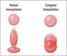
With the birth of digital animation, tweening has come to refer to interpolation performed by software. When a computer tweens, it evaluates the distance between point A and point C, and then divides that distance in half, thereby producing point B. In this regard, a computer’s notion of an inbetween is somewhat more literal than that of a human artist. A trained human artist will also consider concepts like anticipation and exaggeration while animating an object (Figure 2.2).
Figure 2.2 The human interpolation on the left applies a concept called “squash and stretch” to exaggerate the bouncing motion.
Flash CS5 includes three types of tweens: Motion, Shape, and Classic. Classic is the old (pre-CS4) version of the Motion tween. Both Motion and Classic tweens interpolate frames based on the properties of a symbol instance (such as the instance’s position on Stage). A Shape tween interpolates based on the points and curves of two vector shapes.

The inverse kinematic (IK) armature system also allows for tweening. IK is discussed later in this chapter.
Tweens can be very useful, especially for moving objects around on Stage. However, tweens can sometimes appear mechanical and unnatural. There are circumstances in which point B should not reside immediately in between points A and C. For example, objects in real life have inertia, and they sometimes overshoot their destination before settling into position. If you get tween-happy, your audience may notice it. To avoid overapplication of any such effect, first precisely envision what you want your animation to look like, and then figure out how to realize the image in your head. This approach will prevent the software’s tools from dictating your style.
In Chapter 3 you’ll learn how to add Shape Hints to make a Shape tween do your bidding.
The Spring feature added to Flash CS5 is an example of a slightly “smarter” tween that moves more like a real object. To learn more about the Spring feature, see Chris’s article at www.adobe.com/devnet/flash/articles/spring_tool.html.
Whereas tweening interpolates between poses, there is another method that requires the adjustment of poses on every frame. This technique is known as stop motion.
Stop Motion
Stop-motion animation is roughly as old as (or slightly older than) hand-drawn animation. Stop-motion animation consists of arranging objects in front of a camera, snapping a photo, moving the objects slightly, and then snapping another photo. Each photo corresponds to a single frame in the animated sequence.
Stop motion most frequently involves clay (Claymation), puppets, felt, or construction paper. As basic as this technique is, it affords the animator endless conceptual creative license as well as an almost limitless choice of materials to use. The manipulation of actual physical objects often gives stop-motion animation a very tactile feel. Examples of stop-motion animation include Robot Chicken, Gumby, Fantastic Mr. Fox, and Wallace and Gromit.
The frame rate of stop-motion animation varies depending on the project. Stop motion can be extremely labor intensive, but it can also be a way to create animation on the cheap. By repositioning physical objects, you can avoid having to draw thousands of frames of action. Inexpensive animation is generally shot at 12 fps. Several popular stop-motion animations have been made on minimal budgets simply by the arrangement of cutout pieces of paper.
Cutout animation
Animation produced by arranging cutout pieces of paper or fabric (or any flat object for that matter) is known as cutout animation. Since the rise of computer animation, cutout animation can now incorporate digital as well as physical objects. When executed correctly, cutout animation can be a very efficient way to bring your character to life.
Terry Gilliam’s animated sequences from the Monty Python series and films were made using cutout animation.
In 1992, the pop culture phenomenon South Park was first conceived using cutout animation. The prototype incorporated real paper cutouts for a University of Colorado project by Matt Stone and Trey Parker. Since then, South Park has become a wildly popular television series with 14 seasons currently under its belt. Although South Park is now produced digitally (using Photoshop, Illustrator, and Maya), it maintains the simple cutout style of its roots. The success of shows like South Park has led to a proliferation of simply produced, cutout-style animation.
Cutout animation is an efficient and popular Flash animation technique. The use of symbols in Flash facilitates easy manipulation of discrete pieces of artwork. Symbols can easily be moved and scaled to quickly render new frames.
The Flash Animation Boom
In the late 1990s, the Internet became the “wild west” for animators (cutout and traditional) thanks to a simple vector-based animation program called Flash. The first Flash-based animated series on the Internet was The Goddamn George Liquor Program by John Kricfalusi (creator of Ren & Stimpy). More Flash animation began to sprout across the Internet, such as the popular series WhirlGirl, which was also simultaneously televised on the cable network Showtime. The popularity of Flash on the Internet grew exponentially with Happy Tree Friends, The Critic, Joe Cartoon’s Frog in a Blender, Queer Duck, and a handful of clever shorts by JibJab and the Brothers Chaps (homestarrunner.com).
Since then, Flash has continued to spread throughout the Internet and continues to expand its imprint on television. Some of the more noteworthy series to utilize Flash are Home Movies, Mucha Lucha!, Xiao Xaio, Foster’s Home for Imaginary Friends, Atomic Betty, Little Einsteins, Yin Yang Yo, Total Drama Island, Growing Up Creepy, and El Tigre, to name just a few.
Choosing a Technique
Now that you know the animation techniques available, let’s consider how best to design your character in Flash. Your animation can be as simple or as complex as you want it to be. You can borrow from one style to simplify your animation and borrow from another to add an extra bit of nuance. Given Flash’s great capacity for creating cutout-style animation using symbols, you’ll focus on creating a character using this approach. However, you will also utilize tweening, as well as techniques from traditional animation, to create an entertaining but not overly labor-intensive character.
So, without further delay, let’s dive in to the deep end of the Flash pool and examine how to conceptualize a character and bring it to life.
Designing a Character
Years of creating visual content across a variety of media will teach any animator that successful design doesn’t always follow a set of rules. This book focuses on designing characters for interactivity, and therefore some rules are necessary, but these rules should not become strict limitations. Keep your options open when you’re starting to design your character. You can always narrow your focus later.
Conceptualizing
Before putting pencil to paper, the first step is to decide the basic type of character you want to design. Is this character human, animal, insect, alien, or a hybrid of any combination of these categories? If this is a personal project, the sky is the limit. However, you may be creating a project for a client who has already provided a description. It is then up to you to translate that typically verbal information into a unique and tangible visual design.
The difference between good and bad character design can often be a simple matter of starting with a solid plan, even if it’s just a mental plan. A good initial plan can prevent you from aimlessly sketching lines and shapes. In most cases, unplanned drawings result in a failure to create anything visually worthwhile.
On the other hand, the practice of drawing randomly (doodling) is the best way to hone your craft, even if it doesn’t always end up producing something worthwhile or appealing. Good designers are always drawing, whenever time permits, and they always have a drawing pad and pencil nearby in the event there’s two minutes or two hours to kill (Figure 2.3). When Chris worked for an animation production house, he used to always bring his pad and pencil into meetings, because doodling was usually a better use of time than taking notes. As is the case with athletes, artists must exercise their skills frequently to reach their full potential.
Figure 2.3 Doodling is a great way to practice your craft.

Not all designers make good character artists. Additionally, the qualities that combine to generate a great character design can be very subjective. The most important aspect to any character should be its appeal. Good character design is a subtle balance between lines and shapes that are thoughtfully integrated to form a cohesive image. Some happy medium between random doodling and planned sketches will probably produce the best results. The act of doodling can take away the anxiety of a blank page and lead to a more planned and purposeful drawing. Continue to think and sketch until you have a solid character design.
Cleaning up your sketches
After your character design is solidified, you’ll want to clear away any unnecessary lines or artifacts (either with an eraser or an application like Photoshop) that will not be part of your final version. You can then use this cleaned-up character design when you begin drawing in Flash. If your character is drawn on paper, you may want to convert it to a digital format before you begin working in Flash.
At this point, you may even want to create a model sheet to explore your character in more detail. Refer to Chapter 1 for details on model sheets.
Choosing a file format
There’s no best practice when it comes to the format to use when conceptualizing your characters. Some people prefer pencil and paper, whereas others like to remain entirely paperless and draw in programs such as Photoshop, Illustrator, or SketchBook Pro. You can also sketch directly in Flash using any of the drawing tools Flash has to offer. If you have drawings on paper that you’d like to use as the basis for a Flash character, you’ll need a scanner to import your image as a digital file. Most scanners are paired with software that will make this process easy. Some of the more widely used graphic formats that Flash can import are PNG, GIF, JPEG, and TIFF.
When your cleaned-up character sketch is ready in digital format, you can begin constructing your character in Flash.
Building a Character in Flash
Before rendering your character in Flash, consider how your character will need to move. Will your character be walking, running, flying, or falling at any point throughout the project? Optimization and efficiency are key elements for a web project that needs to load quickly and play smoothly. The more times an object can be reused, the more efficient the file will be.
After you import your sketch into Flash, you should consider how the character’s features could best work as individual objects. This process depends ultimately on your style of animation and the style of your character. Efficient use of symbols will facilitate the production of cutout-style animation in Flash.
Working with Symbols
Symbols are the building blocks of Flash. You can convert anything you draw or import into a symbol, and there’s a good reason to do so: When an object is converted into a symbol, it automatically becomes an item in the Flash document’s Library. Every Flash document has its own Library from which you can drag a symbol onto the Stage. When you do so, the object on the Stage is referred to as an instance. No matter how many instances of a symbol reside on the Stage, Flash only needs to load the source symbol once. This is how Flash delivers smoothly streaming animations while maintaining small file sizes. It’s extremely efficient to reuse symbols as many times as possible. You can also apply effects such as Scale, Tint, Alpha, and Brightness to instances and apply Motion Tweens in combination with one or more effects without increasing file size.
When you convert artwork to a symbol, you have a choice of three possible symbol behaviors:
• Movie Clip. Movie Clips are dynamic, which means they can be targeted with ActionScript, the Flash programming language. They can have any number of layers and frames, but their Timelines are independent of all other Timelines. Movie Clips can have Blend Modes and Filters applied to them to achieve sophisticated effects. You will utilize Movie Clips in Chapters 3 and 5 to create custom effects and behaviors. Movie Clips can also be created dynamically at runtime and can also act as a container for other objects, such as external images.
If you are authoring content for video output, see the “Publishing for Broadcast” section in Chapter 5 for more details.
The act of manually moving the playhead back and forth on the Timeline is called scrubbing.
• Button. Buttons have four states: Over, Up, Down, and Hit. These are represented as keyframes in a button symbol’s Timeline. You can place graphics in any of these states and then apply ActionScript to the instance of a button to add interactivity to your Flash movie.
• Graphic. Graphic symbols are similar to Movie Clips except that they are not dynamic and cannot be targeted with ActionScript. Like Movie Clips, Graphic symbols can have any number of frames and layers. Graphics are useful, because their Timelines can be manipulated via the Properties panel. The most important feature of Graphic symbols is that they will always be in sync with parent (Graphic) Timelines and the main Timeline. This feature becomes crucial when you are creating frame-based animations, which is why most animators use Graphic symbols for fixed-frame output formats (such as video). Unlike animation within Movie Clip Timelines, animation nested inside Graphic symbols can be seen when the playhead is moved back and forth along the Timeline within the Flash authoring environment. The only drawback to Graphic symbols is that they do not support Blend Modes or Filters.
In this chapter, you will focus primarily on building a character using Graphic symbols. You will apply a technique known as nesting to easily manipulate the character on the Timeline.
Nesting
The process of nesting involves placing a symbol instance inside another symbol’s Timeline. This allows you to manipulate a symbol and all of its nested objects, or children, as a single object.
Flash animators and developers of all stripes lean heavily on the concept of nesting; thus, nesting will play a large role in the techniques covered in this chapter.
Here’s a simple example of a character designed for cutout animation (Figure 2.4).
Figure 2.4 This diagram shows a character with nested parts designed for cutout animation.

In Figure 2.4, image A shows the monster character as he will appear when the movie is rendered. Image B illustrates how the monster is broken into component parts. Image C shows how the component parts can be animated individually. Because all the parts are stored within a single symbol, the monster can be animated as a whole as well. The next section demonstrates the process of creating a character with nested parts.
Building the Driver Character
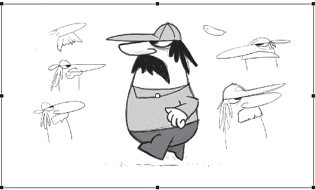
The driver character pictured in Figure 2.5 plays a small role in the Sausage Kong game introduced in Chapter 1. The driver appears after time has elapsed in the game, and he is only seen from the side while he is driving his truck and then when he is running across the Stage. Due to the character’s limited movement, we only need to design a single view of the character.
Figure 2.5 Concept sketches of the driver character.
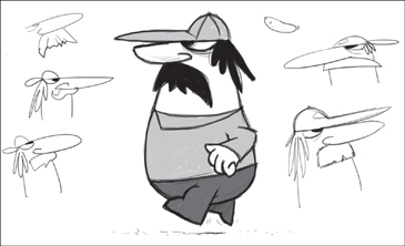
SketchBook Pro was used to create the initial sketches.
Graphics Tablets
A graphics tablet is an input device that allows you to hand-draw images in a manner similar to that of using a pencil and paper. A graphics tablet has a flat surface on which to draw or trace an image using a stylus (a pen-like tool). Some tablets (the Wacom Cintiq, for example) have a built-in screen with which you can directly interact using the stylus. Tablets range from $50 to thousands of dollars (depending on the features) and are a worthwhile investment for any digital artist.
Working with the imported sketch
You’ll use the sketch of the driver as a guide for your Flash artwork.
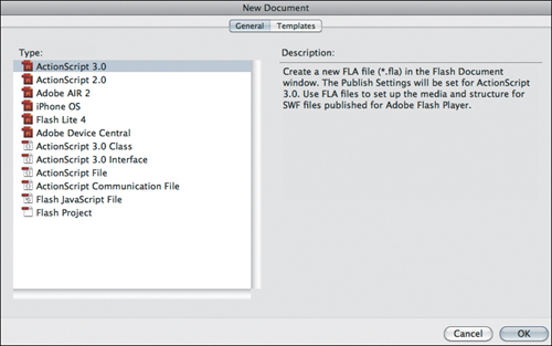
1. Choose File > New, (under the General heading) select ActionScript 3.0 at the left, and click OK to create a new document (Figure 2.6 on the next page).
Figure 2.6 The New Document dialog box allows you to create a new blank document.
2. Save the file as driver.fla.
3. Choose File > Import > Import to Stage, locate the Chapter 2/assets/driver_sketch.tiff file on the accompanying CD, and click Open.
4. With the imported sketch selected, press the F8 key to convert the sketch to a Graphic symbol. Name the symbol sketch, and click OK.
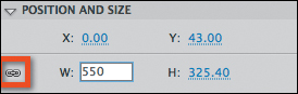
5. In the Position and Size area of the Properties panel, ensure that the chain link icon is unbroken so that width and height will be scaled proportionally, and change the W value to 550 (Figure 2.7).
Figure 2.7 Ensure that the height and width values are locked as you scale the sketch instance.
6. Center the sketch on the Stage (Figure 2.8).
Figure 2.8 The sketch is now centered on Stage.
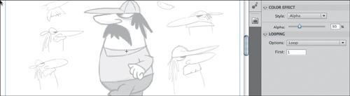
7. In the Color Effect area of the Properties panel, select Alpha from the Style menu and set the Alpha value to 30% (Figure 2.9).
Figure 2.9 The Alpha value settings will render the sketch partially transparent.
8. Rename the current layer sketch, lock the layer, and covert it to a guide by Ctrl-clicking/right-clicking and choosing Guide.
9. Create a new layer named head above the sketch layer.
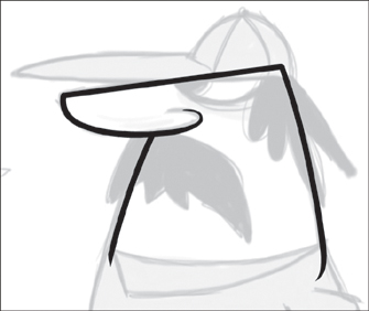
10. Switch to the Brush tool and ensure that object drawing mode is turned off at the bottom of the toolbar. Using a black fill color, trace the outline of just the head shape. Make sure you overlap your drawing where the head meets the neckline of the body to avoid a gap appearing between them when you start animating later (Figure 2.10).
Figure 2.10 The top of the head is outlined to match the rough sketch underneath.
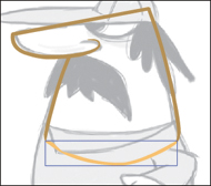
11. Use the Selection tool and Properties panel to soften the black outline to a dark brownish tone (#BE984C), and use the Brush tool to close the neckline gap at the bottom with a line drawn using a lighter yellowish tone (#FFCC66) (Figure 2.11).
Figure 2.11 The neck and head graphic outline drawn using Flash’s Brush tool.
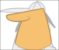
12. Use the Paint Bucket tool to fill in the head with the lighter tone (Figure 2.12).
Figure 2.12 The completed head artwork.
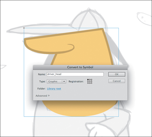
13. Select the entire head artwork and press F8 to bring up the Convert to Symbol dialog box. Name your Graphic symbol driver_head and click OK (Figure 2.13).
Figure 2.13 Convert the head to a Graphic symbol.
14. Save your document.
The next step is to add the eye graphics.
Drawing the driver’s eye
You’ll create three different objects: the shadow of the eye socket, the white of the eye, and the pupil.
1. In your driver.fla file, lock and hide your head layer, and create a new layer named eye.
Several of the figures do not show the sketch layer, but you may want to keep your sketch layer visible for reference.
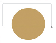
2. Switch to the Oval tool, select the darker fill color (#BE984C) with no stroke, and draw a circle (Figure 2.14).
Figure 2.14 The circle that will become the completed eye.

3. Because the top half of the driver’s eye is designed in a way that it can’t be seen, you’ll cut the circle in half horizontally. Using the Selection tool, drag a marquee over the top half of the circle (Figure 2.15).
Figure 2.15 Use the Selection tool to select the top half of the circle.
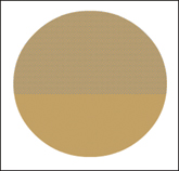
When you release the Selection tool, the upper half of the circle will be selected (Figure 2.16).
Figure 2.16 The partially selected circle will appear with small dots to indicate the selected area.
4. Press the Delete key to remove the top half of the circle (Figure 2.17).
Figure 2.17 The resulting semicircle.

5. Switch to the Free Transform tool, and rotate and scale the semicircle to fit the eye shape on the sketch (Figure 2.18).
Figure 2.18 Use the Free Transform tool to rotate the semicircle.
For several of the steps in this section, if you require precision when adjusting shapes using the Selection or Free Transform tools, turn off snapping in the toolbar while making adjustments.
6. For the eyeball, copy the semicircle (Command+C/Ctrl+C) and paste a copy in place (Command+Shift+V/Ctrl+Shift+V). Scale down the new shape and replace the fill color with white (Figure 2.19).
Figure 2.19 The eyeball shape is now in place.
7. Use the Brush tool (or the Oval tool) with a black fill to add a pupil (Figure 2.20).
Figure 2.20 A pupil is added to the eye.

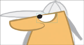
8. Turn the head layer visibility on. Select the eye layer and group the eye parts together (Command+G/Ctrl+G). Use the Free Transform tool to position and rotate the eye to fit on the head (Figure 2.21).
Figure 2.21 The completed eye is now in place.
Save your file, and let’s get a cap on this fella!
Drawing the driver’s hat
The hat is drawn in a manner similar to the eye. You’ll start with basic shapes and then manipulate them into something more complex.
1. Lock and hide all of your existing layers and create a new layer named hat.
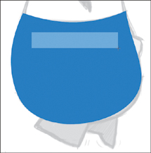
2. Use the Oval tool to draw a circle with a light blue fill (#58A3ED) and no stroke (Figure 2.22).
Figure 2.22 The initial circle created with the Oval tool for the character’s hat.

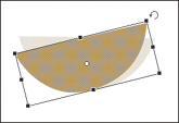
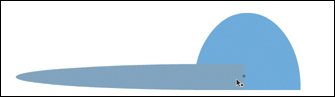
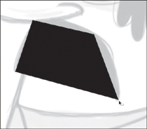
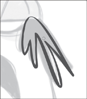
3. Use the Transform tool to squash the circle to a very thin oval (Figure 2.23).
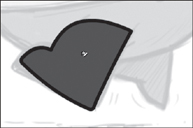
Figure 2.23 The squashed shape will form the brim of the hat.
![]()
4. Using the Selection tool, draw a marquee over the right half of the thin oval and press the Delete key (Figure 2.24).
Figure 2.24 The hat now has a flat right edge.

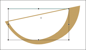
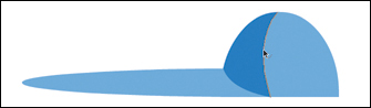
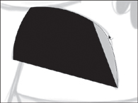
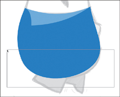
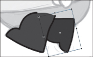
5. Create a larger light blue circle, but this time select and delete the bottom half of the circle (Figure 2.25).
Figure 2.25 The second shape with a flat bottom edge.

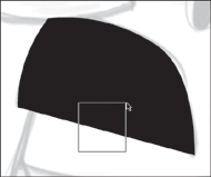
6. Use the Free Transform tool to stretch the current shape vertically (Figure 2.26).
Figure 2.26 The semicircle stretched vertically using the Free Transform tool.
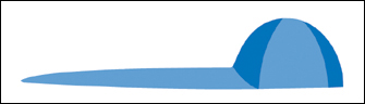
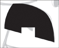
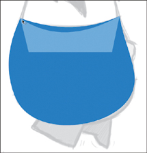
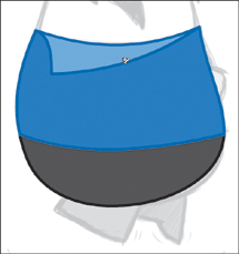
7. Use the Selection tool to align the bottom edges and merge the two light blue shapes together. The end result should look like a hat with a brim (Figure 2.27).
Figure 2.27 The driver’s hat with a brim.
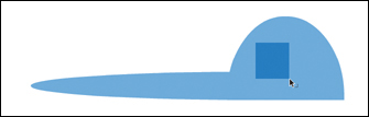
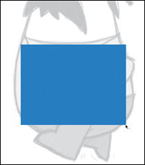
8. To add a two-tone color design to the hat, use the Rectangle tool to create a dark blue (#0066CC) rectangle inside the hat (Figure 2.28).
Figure 2.28 The first step in applying a two-tone color to the hat.
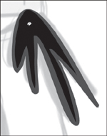
9. Switch to the Selection tool and make sure the Snap feature is on in the toolbar (Figure 2.29).
Figure 2.29 The Snap feature in the toolbar must be turned on.
![]()
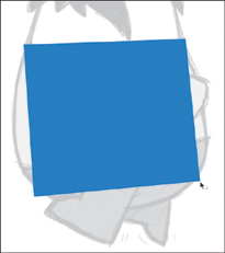
10. Using the Selection tool, drag each corner so that the bottom edges (Figure 2.30) and the top edges (Figure 2.31) of the shape snap to the edges of the hat.
Figure 2.30 Use the Selection tool to snap the color patch to the bottom and left edges of the hat.

Figure 2.31 Use the Selection tool to snap the top of the shape to the edge of the hat.
11. Use the Paint Bucket tool to fill in the left edge (Figure 2.32).
Figure 2.32 You can use the Paint Bucket tool to fill in the final piece of the dark blue shape.
You may need to adjust the Gap Size of the Paint Bucket tool in the toolbar to avoid filling in the entire hat.
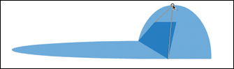
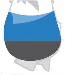
12. Use the Selection tool to curve the right edge of the dark blue shape as if the hat were three-dimensional (Figure 2.33).
Figure 2.33 Use the Selection tool to curve the darker shape toward the edge of the hat.
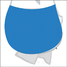
13. Repeat the last several steps (8–12) to create a second dark blue area at the right side of the hat (Figure 2.34).
Figure 2.34 A second dark blue area is added to the hat.
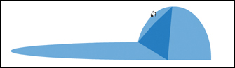
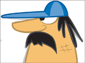
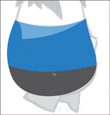
14. To be consistent with the rest of the character’s design style, use the Ink Bottle tool to add an extra dark blue (#004D9B) stroke to outline the entire hat (Figure 2.35).
Figure 2.35 The completed hat artwork.

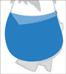
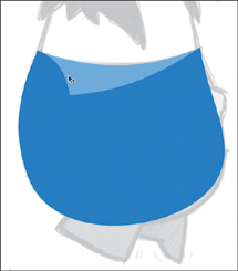
15. Select the entire hat, group it together (Command+G/Ctrl+G), unhide the sketch layer, and use the Free Transform tool to position and scale the hat so that it fits on the driver’s head (Figure 2.36).
Figure 2.36 Use the Free Transform tool to make the hat appear as though it fits on the driver’s head.
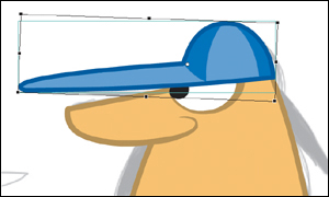
Hold the Shift key to constrain proportions when using the Free Transform tool.
Looking good so far! It’s time to add some facial hair.
Drawing the driver’s mustache and hair
The mustache, like the previous parts of the character, is initially drawn as a basic shape and then can be manipulated into more complex artwork.
1. Lock and hide your previous layers so that you can see only the sketch layer underneath. Create a new layer named hair.
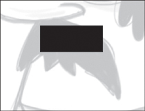
2. Switch to the Rectangle tool with a black fill color and no stroke. Draw a rectangle in the area of the mustache (Figure 2.37).
Figure 2.37 A simple rectangle is all that is needed to begin the mustache shape.
3. Use the Selection tool to pull the corners of the shape into the basic shape of the mustache in the original sketch (Figure 2.38).
Figure 2.38 The Selection tool is used to pull the mustache into its general shape.
4. Use the Selection tool to alter the edges of the shape to create rounded corners and curves (Figure 2.39).
Figure 2.39 The Selection tool is used to curve the edges of the shape.
5. Use the Selection tool to drag a selection at the bottom edge of the mustache shape (hint: Start your selection below the mustache and drag up) (Figure 2.40).
Figure 2.40 The Selection tool is used to select a portion of the shape.
6. With this small section selected, press the Delete key (Figure 2.41).
Figure 2.41 A piece is now removed from the shape.
7. Use the Selection tool to pull the corners of the cutout piece to create the suggestion of points on the mustache.
8. Repeat the last few steps (5–7) to create as many individual points as you desire (Figure 2.42).
Figure 2.42 The mustache now contains a couple of points.
9. Use the Ink Bottle tool to add a dark grey (#333333) outline color to the mustache. You can then use the Brush tool (with the dark gray fill) to extend the outline in some areas to suggest a slight amount of depth (Figure 2.43).
Figure 2.43 The outlined mustache.
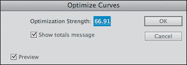
10. Select the entire mustache and choose Modify > Shape > Optimize. In the Optimize Curves dialog box, adjust the Optimization Strength to achieve as much optimization possible while retaining the integrity of the original drawing (Figure 2.44).
Figure 2.44 The Optimize Curves dialog box allows you to reduce the number of vector points needed to render the mustache.
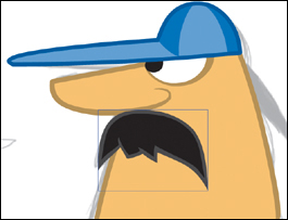
11. Use the Selection tool to select the entire mustache shape and group it together (Command+G/Ctrl+G). Show your other layers and use the Free Transform tool to position and scale the mustache (Figure 2.45).
Figure 2.45 Place the mustache into position on the face.
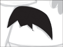
12. Hide all layers except the hair and sketch layers. Use the Brush tool with a dark grey fill (#333333) to draw the outline of the driver’s hair (Figure 2.46).
Figure 2.46 The outline of the driver’s hair.
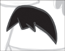
13. Use the Paint Bucket tool to fill the outline of the hair with black (Figure 2.47), and then select the entire shape and group it together.
Figure 2.47 Fill in the hair outline with black.
14. Move the hat layer above the hair layer so that the hair appears underneath the hat.
15. Show all of your layers. Create a new layer named grit. On this layer, use the Brush tool to add some darker-colored (#BE984C) grit to this hard-working driver’s face (Figure 2.48).
Figure 2.48 The driver’s face is completed with a little bit of grit.
16. Now that the facial features are complete, let’s move all the elements into the driver_head symbol for easy manipulation later. Unlock all layers except the sketch layer. Select the frames in the grit, hat, hair, and eye layers that you created. Ctrl-click/right-click on the selected frames and choose Cut Frames.
17. Switch to the Selection tool, and double-click on the driver_head instance to edit the symbol.
18. Create a new layer, Ctrl-click/right-click on that layer’s first frame, and choose Paste Frames.
19. With the artwork still selected, drag the set of features into place within the symbol. Note that your driver_head Timeline has retained the grit, hat, hair, and eye layers.
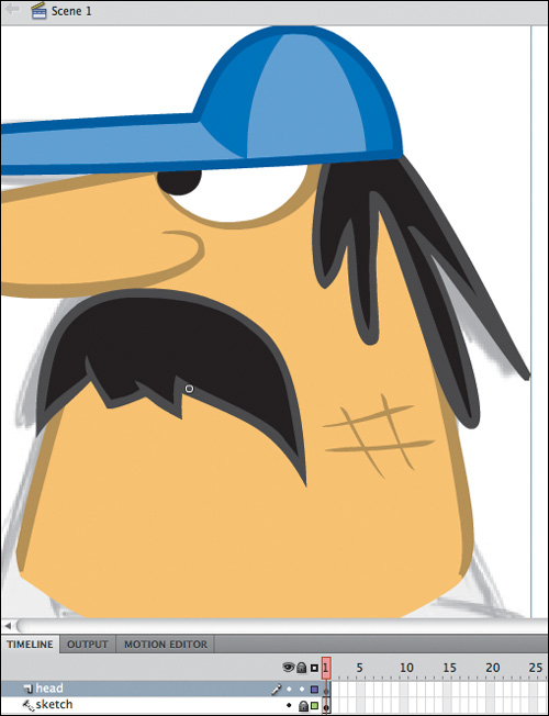
20. Return to the main Timeline by clicking Scene 1 at the top-left, and delete the empty layers. Your main Timeline should now have only a head layer and a sketch layer (Figure 2.49).
Figure 2.49 The driver’s head is now in one symbol, and the main Timeline is nice and clean.
21. Save your document.
Now that the driver’s head is complete, you can start working on the rest of the body.
Drawing the driver’s torso
The creation of the torso will begin in the same fashion as the previous elements.
1. Hide your head layer, and create a new layer above it named body.
2. Use the Rectangle tool to draw a shape with a blue fill (#0066CC) and no stroke that approximates the driver’s body (Figure 2.50).
Figure 2.50 This rectangle will form the driver’s body.
3. Use the Selection tool to pull each corner so that the rectangle more accurately resembles the size and shape of the body in the sketch (Figure 2.51).
Figure 2.51 The adjusted body shape.
4. Pull the sides to create curves that resemble the body in the sketch (Figures 2.52 and 2.53).
Figure 2.52 Adjust the curves one at a time.
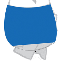
Figure 2.53 Continue adjusting the curves until the shape matches the original sketch.
5. Draw a second rectangle with a light blue fill color (#58A3ED) inside the body shape. This will be the shirt collar (Figure 2.54).
Figure 2.54 The light blue rectangle will form the shirt collar.
6. With the Snap feature selected, use the Selection tool to snap the corner points of the collar shape to the corner points of the shirt shape. Bending the top edge of the collar shape will help make this easier (Figure 2.55).
Figure 2.55 Use the Selection tool to reshape the collar.
7. Continue bending edges, and use the Paint Bucket tool, if necessary, to fill in the top of the collar (Figure 2.56).
Figure 2.56 The collar is flush with the top of the torso.
8. Bend the left edge of the collar shape inward so that it appears as though the collar is sitting on top of the shirt (Figure 2.57).
Figure 2.57 The completed collar.
9. To create the pants, use the Selection tool to select the bottom third of the body shape (Figure 2.58).
Figure 2.58 Use the Selection tool to drag a rectangular selection at the bottom third of the torso.
10. With this area still selected, select a dark gray (#333333) fill color from the Properties panel (Figure 2.59).
Figure 2.59 The driver’s pants now sport a separate color.
11. Deselect all (Command+Shift+A/Ctrl+Shift+A), and then use the Selection tool to bend the shape where the two colors meet at the waist. This will suggest some volume to his torso (Figure 2.60).
Figure 2.60 The adjusted waistline.
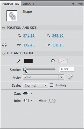
12. Use the Ink Bottle tool to apply a dark blue (#004D9B) stroke to the shirt and a black (#000000) stroke to the pants. If necessary, select your stroke with the Selection tool and use the Properties panel to adjust its thickness (Figure 2.61).
Figure 2.61 You can adjust the width of the stroke in the Properties panel.
13. Add a dark blue stroke around the collar as well (Figure 2.62).
Figure 2.62 The driver’s torso and pants outlines are now complete.
14. Select the contents of the body layer and convert them to a single Graphic symbol (F8) named driver_body.
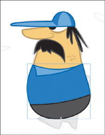
15. Show your head layer and reposition the body and head as necessary. The collar should be slightly wider than the head symbol to ensure that when the head moves, it remains behind the body symbol (Figure 2.63).
Figure 2.63 The driver’s collar is slightly wider than his face.
16. Save your document.
Now that you have the head and the body, only the extremities remain.
Drawing the driver’s limbs
A character’s arms and legs are essential to creating the illusion that the character is walking or running. Thus, the corresponding artwork will require a bit of extra detail.
1. Hide the head and body layers to reveal the sketch underneath. Create a new layer named arm.
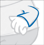
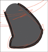
2. Use the Brush tool with a dark blue fill (#004D9B) to draw the outline of the sleeve (Figure 2.64).
Figure 2.64 The outline of the sleeve drawn with the Brush tool.
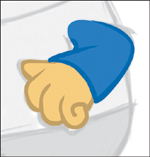
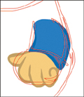
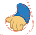
3. Use the Brush tool with a dark skin fill (#BE984C) to draw the outline of the hand (Figure 2.65).
Figure 2.65 The outline of the hand drawn with the Brush tool.

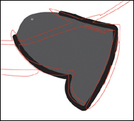
4. Switch to the light blue fill color (#0066CC) and draw a shoulder to close the sleeve (Figure 2.66).
Figure 2.66 Gaps are removed along the outline of the shape in order to add the fill.

5. Use the Paint Bucket tool with the same blue color to fill the sleeve. Then use the Paint Bucket tool with the lighter skin color (#FFCC66) to fill the hand. (Figure 2.67).
Figure 2.67 The completed arm.
Normally, when designing a character, you might draw the arms in a relatively relaxed position. However, because this driver will be running, the character has been designed to be in a running pose from the start.
6. Select the entire arm and convert it to a symbol named driver_arm.
You’ll now create the two legs using a single symbol. The driver’s leg and foot will be drawn as one object. In many cases the leg and foot are broken down into three parts: upper leg, lower leg, and foot (or shoe). This character is somewhat simple because his only tasks are to stand still and run.
1. Lock and hide the arm layer, and create a new layer above it named front leg.
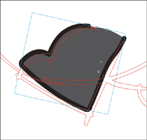
2. Draw a rectangle with a dark gray fill (#333333) and no stroke to begin the leg shape (Figure 2.68).
Figure 2.68 The leg starts with a simple rectangle.
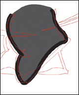
3. Using the Selection tool, pull the corners of the shape until it roughly resembles the shape in the sketch (Figure 2.69).
Figure 2.69 Adjust the shape using the Selection tool.
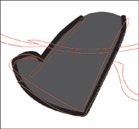
4. Continue using the Selection tool to pull the edges of the shape to create contours that closely match the leg in the sketch (Figure 2.70).
Figure 2.70 The contoured leg shape.
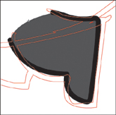
5. Draw a second, smaller rectangle for the foot (Figure 2.71).
Figure 2.71 The smaller rectangle will form the foot.

6. With the Snap feature on, use the Selection tool to snap the corner points to the leg and bend the edges to create the contours and curves that resemble the sketch (Figure 2.72).
Figure 2.72 Use the Selection tool to reshape the foot.
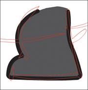
7. Use the Ink Bottle tool to add a black stroke to the completed shape (Figure 2.73).
Figure 2.73 The completed leg artwork.
8. Convert the entire leg to a Graphic symbol (F8) named driver_leg. Instead of drawing a second leg, you’ll reuse the symbol you just created.
9. Copy your leg instance (Command+C/Ctrl+C), and create a new layer named back leg below the body layer. Paste (Command+V/Ctrl+V) the leg into your new layer and lock the front leg layer.
10. Use the Free Transform tool to rotate and position the back leg; you may want to make it slightly smaller to suggest perspective (Figure 2.74).
Figure 2.74 The back leg in position.

11. In the Properties panel, in the Style menu under Color Effect, select Tint. Apply black as the tint color with a Tint value of about 33% (Figure 2.75). This will darken the second leg slightly, pushing it back as if in shadow (Figure 2.76).
Figure 2.75 Apply a tint via the Properties panel.
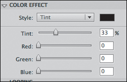
Figure 2.76 The back leg with the tint applied.
Now you want to encapsulate your entire character (head, hat, eyes, mustache, hair, etc.) into a single symbol that can be moved and scaled as one object.
1. Select all of your frames (including the one on the sketch layer), Ctrl-click/right-click, and choose Cut Frames.
2. Choose Insert > New Symbol, and create a new Movie Clip symbol named driver.
3. Inside your new symbol, Ctrl-click/right-click on the first frame, and choose Paste Frames. All your layers should be intact (Figure 2.77).
Figure 2.77 All the driver’s layers are now inside the driver symbol.
4. Create a new layer just above the sketch layer named shadow.
5. Use the Oval tool with a black fill (no stroke) mixed with about 20% Alpha transparency to draw flattened oval.
6. Select the oval and convert it to a symbol named driver_shadow (Figure 2.78).
Figure 2.78 The shadow adds an extra bit of realism to the character.
7. You can now hide your sketch layer, because you no longer need it, and return to the main Timeline by clicking Scene 1 at the top-left corner of your screen.
8. Create a new layer named driver, and drag an instance of the driver symbol from the Library onto the Stage. Delete all layers on your main Timeline except for the driver layer.
9. Save your document.
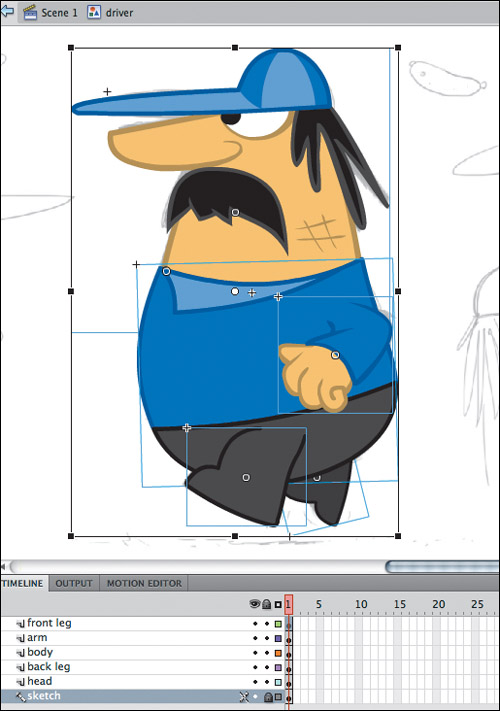
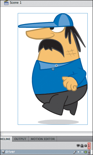
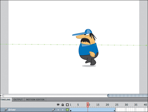
Congratulations! The driver character is complete and ready for animation (Figure 2.79).
Figure 2.79 The final character, composed of individual symbols, is ready for animation.
Now that you’re almost rolling, let’s get that character prepped for animation.
Animating a Character
Traditional cartoon characters typically share a common design thread: They have eyes, a nose, ears, hair, a mouth, a torso, arms, hands, legs, and feet. As much as all of these objects augment the visual appeal of a character, they also complicate the roles of the designer and animator. The animation workflow grows exponentially because of all these elements, and the animator can quickly feel over-whelmed before even having started. Character designs vary infinitely, which leads to an unlimited number of ways in which they can be rigged for animation.
The term rigging is used to describe the process of preparing and assembling assets for character animation into a virtual skeleton of sorts. There are a couple of different techniques that can be employed to rig a character in Flash. This section begins by showing you how to rig your character manually, which will facilitate small adjustments. Later in the chapter, you’ll look at rigging objects with Flash’s built-in skeleton system, the IK Bone tool. However you rig your character, the limbs should have joints that allow the character to move in an anatomically feasible manner.
Let’s begin by rigging the driver character that you created in the previous section.
Animating the Driver Character
The driver character’s main task in the game is to run from his truck to a pile of sausages, pick them up, and throw them into the back of his truck. Then he runs back into his truck and drives away. Let’s prep his joints for running.
Creating joints
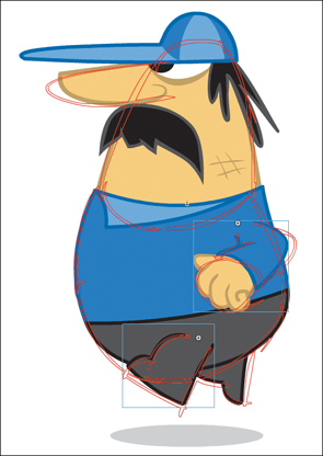
The first step is to hinge each body part so that it rotates appropriately. Using the Free Transform tool, you’ll select each symbol and adjust the small white circle to the appropriate area.
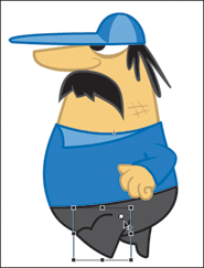
1. Double-click on your driver symbol to enter symbol edit mode, and use the Free Transform tool to adjust the point of rotation for each leg symbol so that it will hinge where the top of each leg meets the body. This center point becomes the character’s hip (Figure 2.80).
Figure 2.80 The hip joint for the front leg.
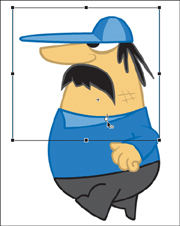
2. Use the Free Transform tool to adjust the point of rotation for the arm. The arm symbol should hinge where it meets the body. This center point becomes the character’s shoulder (Figure 2.81).
Figure 2.81 The shoulder joint for the arm.

3. Use the Free Transform tool to adjust the point of rotation for the head so that the head symbol hinges where it meets the body. This center point becomes the character’s neck (Figure 2.82).
Now that your character is rigged, you can easily alter your character’s poses.
Creating the driver’s run cycle
A run cycle (or walk cycle) is a loop of a stationary character performing running (or walking) movements. That cycle can then be played while the character is in motion. In Chapter 3 you’ll learn how to make your character run at varying speeds using ActionScript.
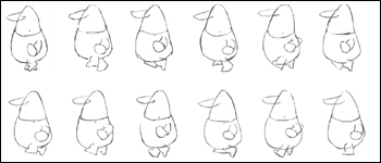
The first step is to create a rough animatic sketch of the run cycle to use as a guide. You can draw your own animatic sketch or use the one provided in the Chapter 2/assets folder on the CD (Figure 2.83).
Figure 2.83 Frames from the sample animatic of the run cycle.
To create the animatic in Flash:
1. Open your driver.fla document and save it as driver_run_cycle.fla.
2. Double-click your driver instance on the Stage to edit the symbol.
3. Select frame 12 on every layer and extend the frames (F5) on those layers. You’re aiming for a 12-frame run cycle.
4. Create a new layer at the top to house your animatic and name it rough.
5. Turn on the Onion Skin feature in the Timeline so that you’ll be able to see the adjacent frames for reference as you draw. You can adjust the bracket-like Onion Skin handles at the top of the Timeline to control how many forward or backward frames appear.
6. Use the Brush tool to sketch how you imagine the driver might run frame by frame. Add a keyframe (F6 or F7 for a blank keyframe) for each frame as you go.
You can use the Chapter 2/assets/rough_animatic.fla file as a guide, or you can copy the frames and paste them into your driver_run_cycle.fla file.
7. After using the first frame as a reference for position, you may want to hide all layers except the rough layer, so you can focus on the animatic.
8. As you keyframe each pose, play back the animation (Return/Enter) to make sure the drawings move the way you want them to. Continue to make any adjustments necessary. The key here is to animate the character running in place as if it is on a treadmill. This way you can place all the keyframes in a symbol and control the speed and direction of the character using either a Motion Tween or ActionScript.
When you’re satisfied with how your animatic moves, you can apply the corresponding adjustments to the driver character.
1. Show the layers containing the driver’s body parts. Double-click on the little color swatch to the right of the layer name (“rough”) to open the Layer Properties panel (Figure 2.84).
Figure 2.84 Double-click on the outline toggle to open the Layer Properties panel.
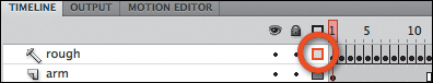
Set the Outline color to red and make sure the “View layer as outlines” check box is selected (Figure 2.85).
Figure 2.85 The Layer Properties panel allows you to change the outline color of a layer.

2. Ensure that your animatic overlaps the character on all 12 frames, and then hide all layers except for the rough and arm layers.
3. Using the outline of the rough animatic as a guide, rotate and position the arm symbol on each frame, adding all 12 keyframes (F6) as you progress (Figure 2.86).
Figure 2.86 Rotate the arm to match the rough animatic.
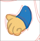
4. If you want to go the extra mile on this character, you’ll need to draw a few different arms as needed. There will be some frames where the arm might need to be slightly more bent at the elbow, and in other frames you may need a new arm that is in a slightly different perspective (Figure 2.87).
Figure 2.87 A new, slimmer drawing of the arm was created to match the animatic.
You can also simply use the single arm symbol and then rely on the Free Transform tool to skew the perspective, but often it doesn’t accomplish the same level of realism. In most cases, each drawing you make of the arm can be reused in other frames and will only require some rotation and repositioning.
You may have to draw new arms on some frames that have a slight bend to them and a little more foreshortening (Figure 2.88).
Figure 2.88 A more bent and foreshortened arm.
On other frames, the arm will need to be bent even more and positioned further back on the body (Figure 2.89).
Figure 2.89 An arm that is bent and pulled back.

When you’ve completed keyframing the arm layer and you’re happy with the resulting motion, you can begin animating the legs.
1. The leg is animated in much the same way as the arm. Hide the arm layer, and unhide the front leg layer.
2. Use the rough animatic as a guide to position and draw (when necessary) each new keyframe so that the front leg is rendered appropriately (Figure 2.90).
Figure 2.90 The front leg is rotated to match the animatic.
3. Similar to the arms, you may want to redraw some of the frames to match the animatic more accurately. The leg in this frame is descending downward toward the ground (Figure 2.91).
Figure 2.91 A redrawn front leg.
4. When the leg is fully against the ground, you may want to redraw its bottom edge flat and wide to suggest weight (Figure 2.92).
Figure 2.92 The flattened bottom of the foot suggests weight.
5. When the leg is starting to come up off the ground, you can emphasize this by drawing a bend so that the toe is still in contact with the ground while the heel is curved upward (Figure 2.93).
Figure 2.93 The foot drawn as though the heel were lifting off the ground.
6. When the foot is completely off the ground, you can reuse the original leg shape (Figure 2.94).
Figure 2.94 The leg returns appropriately to its original shape as the foot leaves the ground.
7. Bend the knee as the foot starts to move forward (Figure 2.95).
Figure 2.95 The knee is bent as the leg begins to move forward.
8. You can curve the arch of the heel as the leg is still moving forward to emphasize an upward direction (Figure 2.96).
Figure 2.96 The shape of the foot can indicate the direction in which the leg is traveling.

9. As the leg continues to move forward, you may want to rotate it so that the toe is pointing more forward in the direction of the run cycle (Figure 2.97).
Figure 2.97 The toe begins to point forward in the direction of the motion.
10. Straighten the leg out just before it begins its descent toward the ground again (Figure 2.98).
Figure 2.98 The leg is straightening out to touch the ground again.

Continue to hone the front leg until you’re satisfied with the resulting animation.
In the following steps, you will nest your arm and leg animations in new symbols. Nesting these animated parts can allow for the layering of animations inside other animations to produce very sophisticated results. Once you nest the arm and leg animations in new symbols, you will easily be able to animate both symbols as single objects.
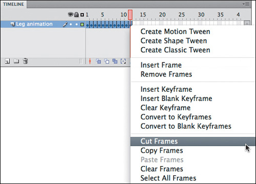
1. Select all the frames in the front leg layer, Ctrl-click/right-click, and select Cut Frames (Figure 2.99).
Figure 2.99 Cut all the frames of your animated leg.
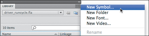
2. In the Library panel, select New Symbol from the menu in the top-right corner (Figure 2.100).
Figure 2.100 Create a new symbol from the Library panel.
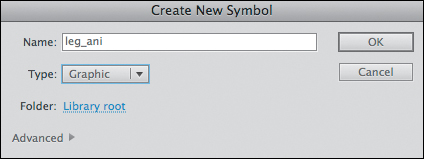
3. In the Create New Symbol panel, enter a descriptive name (e.g., leg_ani) and select Graphic from the Type menu (Figure 2.101).
Figure 2.101 The Create New Symbol dialog box.
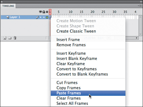
4. Ctrl-click/right-click on frame 1 of this new symbol and select Paste Frames (Figure 2.102).
Figure 2.102 Select Paste Frames from the context menu.
5. Repeat steps 1–4 for the arm animation.
6. With both the arm and leg animations nested in their own symbols, drag the new animated symbols back into the original (arm and front leg) layers within the driver symbol and position them appropriately on the character’s body. As individual symbols, the arm and leg animations are now much easier to animate (Figure 2.103).
Figure 2.103 Position the nested animations to match the rough outlines.
7. Ctrl-click/right-click on the back leg symbol and select Swap Symbol. In the Swap Symbol dialog box, select the animated leg symbol and click OK. The updated instance should retain the rotation, scaling, and tint that you added previously.
8. Set the First (frame) value in the Properties panel to 7 (and the Options to Loop) so that the back leg motion complements the front leg (i.e., they are six frames apart in a 12-frame loop).
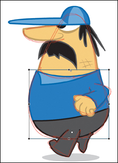
9. Using the rough animatic as your guide, animate the driver’s body by positioning and rotating his symbols on new keyframes to match the poses, just as you did with the arm and leg (Figure 2.104).
Figure 2.104 Scale, rotate, and position the body to match the animatic.
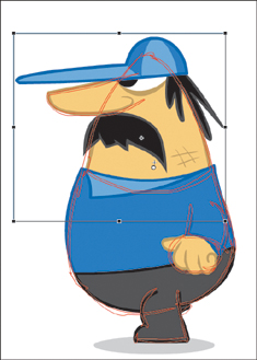
10. Match the head to the animatic positions as well, adding keyframes when needed (Figure 2.105).
Figure 2.105 Scale, rotate, and position the head to match the animatic.
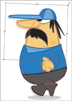
11. Continue to make further adjustments as needed. When you adjust one piece, it may force you to adjust another piece to match (Figure 2.106).
Figure 2.106 Continue to make adjustments using the Free Transform tool.
12. Once you’ve finished animating the driver’s component parts, return to the main Timeline and save your document. This document will be used later to animate the driver dynamically.
You’ll now animate your driver’s run using a Motion Tween.
1. Save a new copy of your document as driver_animation.fla.
2. Move the driver instance to the right edge of the Stage, Ctrl-click/right-click on the instance, and choose Create Motion Tween.
3. With the playhead on the last frame of the tween, move the driver to the left edge of the Stage.
4. In the Properties panel, change the Instance behavior to Graphic and press Return/Enter to preview your animation to see the driver run across the Stage (Figure 2.107).
Figure 2.107 The driver runs across the main Timeline using a Motion Tween.
If you want your character to run left to right, turn your character around by choosing Modify > Transform > Flip Horizontally before adding a tween.
Adjust the frame duration of the driver layer as needed to match the tween speed with the driver’s run cycle.
Congratulations! You have a fully animated character! Now that you know how to rig and animate your character by hand, let’s look at inverse kinematics.
Animating a Character with Inverse Kinematics
Inverse kinematics (IK) is a method for animating an object or set of objects in relation to each other using an articulated structure of bones. Bones allow symbol instances and shape objects to move in complex and naturalistic ways with a minimum of design effort. A system of bones created with IK in Flash is known as an armature. You can create armatures using several symbols or using a single shape. When you move a single bone, the connected bones move as if connected by joints. You’ll use the Bone tool in the following exercises to create two different types of armatures.
Creating an armature using symbols
Let’s start by building a basic armature using symbols.
1. Choose File > New, (under the General heading) select ActionScript 3.0 at the left, and click OK.
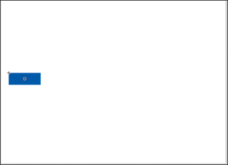
2. Use the Rectangle tool to draw a rectangle on Stage with a solid fill (Figure 2.108).
Figure 2.108 A rectangle drawn on the Stage.
3. Convert the rectangle to a Graphic symbol (F8) named segment.
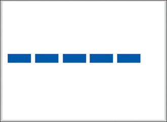
4. Drag four copies of your rectangle on Stage so that you have a line of five segments in a row (Figure 2.109).
Figure 2.109 The five instances of the segment symbol will be used to connect the “bones” of the armature you are about to create.
Press the Option/Alt key to simultaneously drag and duplicate an element on the Stage.
5. Switch to the Bone tool (Figure 2.110).
Figure 2.110 The Bone tool can be found in the toolbar.
![]()
6. Click on the center of the leftmost segment instance, drag to the next segment, and release (Figure 2.111).
Figure 2.111 The first bone is drawn from the leftmost segment to its neighbor.
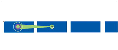
When you apply the first bone to the first symbol in an armature, that symbol becomes the parent bone by default. All subsequent bones will be children of the parent bone.
This creates the first bone in your armature.
7. Now drag from the second segment to the third and repeat until all the segments are joined (Figure 2.112).
Figure 2.112 The completed armature.
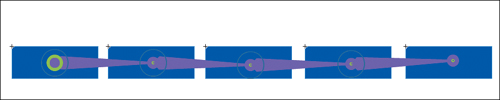
You now have a complete armature.
8. Switch to the Selection tool and try dragging the right-most segment. Notice how the segments are linked like joints (Figure 2.113).
Figure 2.113 The manipulation of one segment can affect the entire armature.
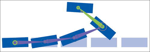
You can quickly see how an armature could be useful in quickly rigging an animated character.
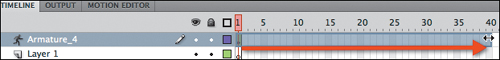
9. When you begin applying bones to your symbols, Flash will automatically move your artwork to a new Armature layer. Drag out the first frame of your Armature layer to frame 40 (Figure 2.114).
Figure 2.114 Drag the frame to extend the Armature layer’s Timeline.
10. Reposition your Armature layer using the Selection tool (Figure 2.115).
Figure 2.115 Reposition the armature on frame 40.
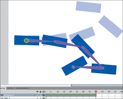
11. Press Return/Enter to preview your animation on Stage.
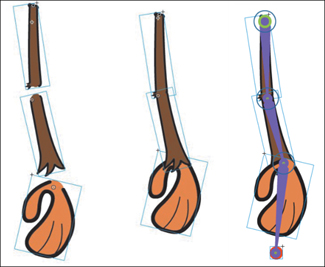
Congratulations! You’ve just animated an armature! To apply this technique to a character, you would simply need to use your character’s body parts rather than rectangles. In some cases, you may be able to rig a character’s entire body as an armature. This will depend heavily on your character design. In most situations, you will exert more control over your character’s poses if you rig your character’s limbs separately (Figure 2.116 on the next page). It’s important to note that each piece of your armature serves as a joint, so in many cases, you’ll need to create a dummy symbol to use as a handle at the end of your armature (as illustrated in Figure 2.116).
Figure 2.116 An illustration of a monkey character’s arm rigged using IK. The red circle symbol acts as a handle so that the hand can be manipulated.
Now that you can create an armature using symbols as segments, let’s look at how to create a more fluid armature using a shape.
Creating an armature using a shape
The Bone tool can also be used to create an armature entirely within a vector shape. This is a great way to animate and “morph” shapes. In this exercise, you’ll create the beginning of a flexible limb from a plain rectangle.
1. Choose File > New, select ActionScript 3.0 at the left, and click OK.
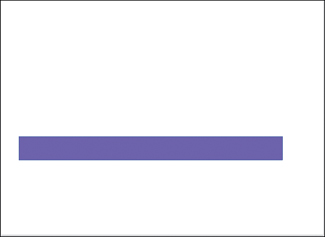
2. Use the Rectangle tool to draw a long rectangle on Stage with a solid fill (Figure 2.117). Instead of converting your shape to a symbol, you’ll jump right to creating an armature.
Figure 2.117 A shape ready to be rigged.
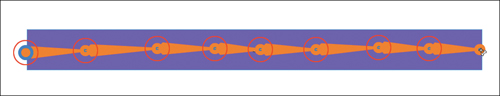
3. Select the Bone tool. Start at the left side of your rectangle and draw several bones until you reach the right side of your rectangle (Figure 2.118).
Figure 2.118 A shape rigged as an armature.
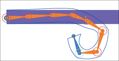
4. Switch to the Selection tool and drag the right side of your armature around the Stage. Notice how the shape bends and deforms (Figure 2.119).
Figure 2.119 You can deform and animate a shape using an armature.
You can now animate your shape armature just as you did with the segmented armature in the previous section.
Both IK rigging and the standard rigging demonstrated earlier in this chapter have their strengths. The speed at which an armature can be created makes IK great for prototypes and rough mockups. If you want absolute control of your character, you will likely want to rig your character and adjust each body part manually.
See more examples of Flash IK armatures at www.cartoonsmart.com/inverse_kinematics.php5.
Now that you know how to get a character walking, let’s get one talking, too!
Adding Dialogue
Animation genres can vary as much as or more than live-action genres. Some animated projects focus entirely on depicting beautiful movement; others are driven almost entirely by dialogue. If you work on enough animated projects, chances are you’ll need to work with dialogue at some point. The task of matching a character’s dialogue to his/her/its mouth to create the illusion of speech is known as lip syncing.
Lip Syncing
Lip syncing can be an extremely laborious process. Having dialogue in your scene almost guarantees you’ll need to make adjustments on nearly every frame. On many projects, lip syncing consumes more time than any other task. Seeing the final result of your labor can be very rewarding, but while you’re in the thick of it, you may feel like there’s no end in sight.
There are also tricks to minimize the amount of lip syncing needed—such as covering a character’s mouth with a mask or drawing your character from behind. But use these tricks sparingly, or your audience will notice that you’re taking shortcuts.
The goal of the following exercises is to show you how to make lip syncing as painless as possible. Flash offers three common lip syncing methods. The first involves drawing a new mouth for your character on every frame to match (or sync) with your character’s dialogue. This frame-by-frame method is arduous and pretty much self-explanatory. The second method involves creating several different mouth symbols and swapping an instance on Stage as needed to match the character’s dialogue. This swapping method is a vast improvement over drawing each frame by hand (Figure 2.120). The third method employs different mouth shapes nested within a Graphic symbol. You’ll focus your efforts on this nesting method.
Figure 2.120 You can swap a selected instance to another symbol using the Properties panel.

A few years ago, when Chris worked at an animation studio, his team would often have two days to complete all the lip syncing for an entire 22-minute show. After having swapped symbols for thousands of frames, he sought a way to reduce the number of mouse clicks required to sync each frame. As a result of this search, the nesting method was born.
The nesting method is made possible by the attributes of a Graphic symbol (discussed previously in this chapter). By manipulating the First (frame) value in the Properties panel, you can control which frame of a Graphic symbol’s Timeline is displayed. Thus, you can use a Graphic symbol as a repository for a certain category of artwork, and you can then access and display that artwork as you see fit from outside the symbol (usually on the main Timeline or whichever Timeline in which your symbol is nested). In this exercise, you’ll create a symbol to hold all the different mouth shapes that you might apply to your character.
If you want to see simple characters animated masterfully, do a search for videos by Don Hertzfeldt.
Creating the mouth symbol
You’ll create a simple character and sync the character’s mouth to the words in an audio file. Even when your animation is extremely simple, good lip syncing (and good timing in general) can make for a convincing and compelling animation.
1. Choose File > New. In the New Document dialog box, switch to the Templates heading, choose Media Playback > Title Safe Area NTSC D1 (Figure 2.121 on the next page), and click OK.
Figure 2.121 The New from Template dialog box allows you to create a new document with a title safe area.
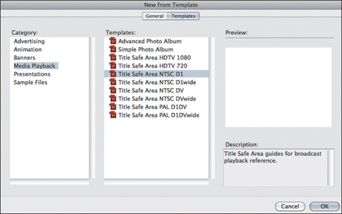
Your new document will already contain a title/action safe guide layer.
2. Save your document as lipsync1.fla.
3. In the Properties panel, set the FPS to 24. The audio clip that you will import is short (~ 1 sec) and fast, so you’ll use a high frame rate to more effectively sync the audio.
4. Select the first frame on the content layer and switch to the Brush tool.
5. Ensure that object drawing mode is turned on within the toolbar (Figure 2.122).
Figure 2.122 Object drawing mode has been toggled on in the toolbar.
![]()
Object drawing mode converts your brush strokes into a distinct object. Object drawing mode is discussed at length in Chapter 4.
6. Choose a solid black fill in the Properties panel.
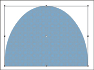
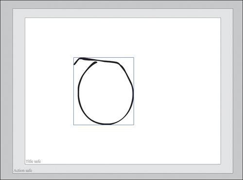
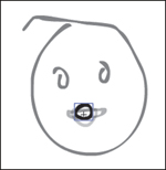
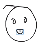
7. Draw a simple shape for your character’s face (Figure 2.123).
Figure 2.123 A simple oval for the character’s face with a little wisp of hair at the top.
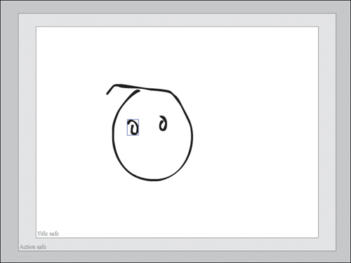
8. With the Brush tool still selected, draw two simple shapes for the character’s eyes (Figure 2.124).
Figure 2.124 The character now has a couple of eyes.
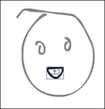
9. Draw an open mouth for the character in the shape of a backwards “C” (Figure 2.125).
Figure 2.125 The character’s mouth is now in place.
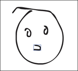
This shape will serve as the character’s default mouth for now, but you’ll create several more mouth shapes in a moment.
10. Switch to the Selection tool, click on the mouth (Shift-click if you need to select multiple parts), and convert the mouth into a symbol (F8).
11. In the Convert to Symbol dialog box, name the symbol mouth, choose Graphic from the Type menu, and make sure the registration point is in the center (Figure 2.126).
Figure 2.126 Convert your mouth shape to a Graphic symbol.
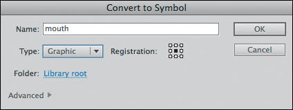
The center registration will serve as a guide so that each of the mouth shapes you create in the next section will be positioned appropriately on the face.
12. Save your document (File > Save).
Now that you have your file set up and your mouth in place, let’s prep the mouth for some incoming audio.
Populating the mouth shapes
A basic unit of sound is referred to as a phoneme. The mouth shape and facial contortions that correspond with vocalizing phonemes are known as visemes. Animators generally refer to phonemes and visemes interchangeably (even though they are technically different concepts).
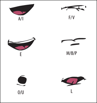
There is a standard set of about six or seven phonemes/visemes (i.e., mouth shapes) that are sufficient to create the illusion of speech on an animated character. The basic shapes correspond to the following spoken sounds (Figure 2.127):
• A as in “cat” and “say,” and I as in “kite” (same shape)
• E as in “street” or “trek”
• O as in “boat” and U as in “clue” (these two are sometimes separated)
• F and V as in “favor”
• M as in “might,” B as in “back,” and P as in “pass”
• L as in “laundry”
Figure 2.127 Six mouth shapes that correspond to the most common phonemes.
When you move or transform your mouth symbol, all nested assets are moved or transformed as well.
You can include more mouth shapes for specific sounds, but at some point, you will find that you reach a point of diminishing returns when you expend a lot of effort for small improvements. Ideally, you’ll be able to find a balance where minimal effort meets maximal reward. On that note, it should be mentioned that simpler mouth shapes tend to work well because they’re only onscreen for a fraction of a second. Simple shapes are also easier for the brain to process in the time available (1/24th of a second, in this case).
You may find it helpful to act out and exaggerate the different sounds as you’re drawing them. Most animators have a mirror handy as well.
Now you’ll draw the basic mouth shapes onto the mouth symbol’s Timeline.
1. Double-click on your mouth symbol to edit its contents.
2. Select frame 2 and insert a blank keyframe (F7).
3. Switch on the Onion Skin feature at the bottom of the Timeline (Figure 2.128).
Figure 2.128 The Onion Skin feature allows you to see faded versions of content on adjacent frames.
![]()
You should now see a light version of the content from the previous frame.
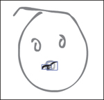
4. Switch to the Brush tool. Using the registration point (the crosshairs) and the onion skin as a guide, draw and position a mouth for an “ah” sound on frame 2 (Figure 2.129).
Figure 2.129 The “ah” mouth shape on frame 2.
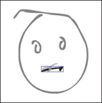
5. Insert a blank keyframe (F7) at frame 3 and draw a mouth shape to match an “eh” sound (Figure 2.130).
Figure 2.130 The “eh” mouth shape on frame 3.
6. Insert a blank keyframe at frame 4 and draw a shape to match an “oh” sound (Figure 2.131).
Figure 2.131 The “oh” mouth shape on frame 4.
This frame will double as “oh” and “ooh” since they are reasonably similar.
7. Insert a blank keyframe at frame 5 and draw a mouth that looks like your character is biting his/her lip for an f/v sound (Figure 2.132).
Figure 2.132 The f/v mouth shape on frame 5.
8. Insert a blank keyframe at frame 6 and draw a mouth that looks like the character is forming an “m,” “b,” or “p” sound (Figure 2.133).
Figure 2.133 The m/b/p mouth shape on frame 6.
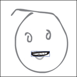
9. Insert a blank keyframe on frame 7 and draw a closed mouth (Figure 2.134).
Figure 2.134 The closed (neutral) mouth shape on frame 7.
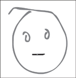
The closed mouth will be useful for separating words when syncing your mouth shapes to the audio.
10. Turn off the Onion Skin feature, and then return to the main Timeline by clicking the Scene 1 button at the top-left corner of the Stage.
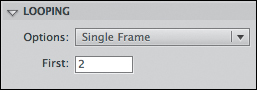
11. Select only the mouth symbol instance on Stage. In the Looping section of the Properties panel, click the Options menu and choose Single Frame (Figure 2.135).
Figure 2.135 The Single Frame option ensures that the Graphic symbol remains on a single frame.
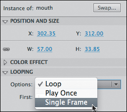
The Single Frame option instructs your symbol’s Timeline to stay put rather than Play Once or Loop (play multiple times). You’ll want your mouth symbol to stay on the frame you’ve assigned until you create a new keyframe for a different mouth shape.
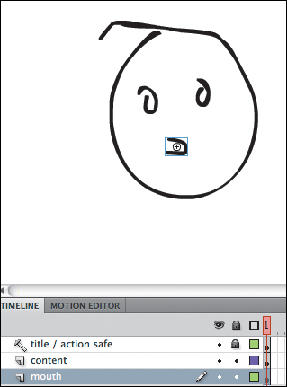
12. Ctrl-click/right-click on the mouth symbol and choose Distribute to Layers (Figure 2.136). This will move the mouth symbol to its own named layer (Figure 2.137).
Figure 2.136 The Distribute to Layers feature is found in the context menu.
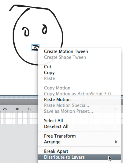
Figure 2.137 The mouth now has its own named layer.
13. Save your document.
Now that your mouth symbol is ready to go, it’s time to bring in some audio.
Importing the audio
You’ll import a short audio clip to whet your lip syncing appetite. This short clip, voiced by John Smick (talented writer, voice actor, and all-around funny guy), will give you a good sense of just how much effort can go into a single second of lip syncing.
1. In your lipsync1.fla document, choose File > Import > Import to Library (Figure 2.138).
Figure 2.138 The Import to Library option lets you bring in external assets like audio files.
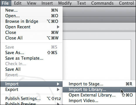
2. Using the Import to Library window, navigate to the Chapter 2/assets folder on the CD, select the Are you kidding me.wav file, and click Open.
3. Create a new layer. Double-click on the layer name and change it to audio.
4. Lock all the layers except the mouth layer.
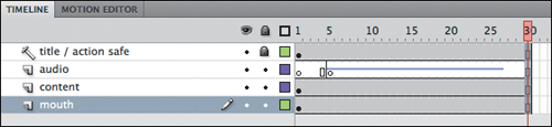
5. Select frame 30 on all four layers and press F5 to extend each layer to frame 30. This will make room for the audio track on the Timeline.
6. Select frame 5 of your audio layer and add a new keyframe (F6). You’ll start the audio on this frame to provide a lead-in before the character begins speaking.
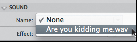
7. With frame 5 selected, in the Sound section of the Properties panel, click the Name menu and choose the Are you kidding me.wav sound (Figure 2.139).
Figure 2.139 The Properties panel allows you to assign a sound item to a keyframe.
Recall from Chapter 1 that you can adjust the height of your audio layer to get a better look at the waveform as you’re lip syncing.
8. Still in the Properties panel, set the Sync to Stream (Figure 2.140).
Figure 2.140 The Stream setting allows you to sync your mouth shapes to the audio.
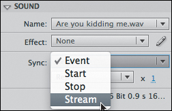
Now that your sound is configured to Stream, you’ll be able to match the audio to the mouth shapes you’ve created. You should now see your audio’s waveform on the Timeline (Figure 2.141).
Figure 2.141 The waveform is displayed on the audio layer.
9. Add a keyframe (F6) to frame 5 of your mouth layer. You will begin syncing on this frame in the next exercise.
10. Save your current document (File > Save As) as lipsync2.fla.
With your audio in place and your mouth symbol ready to go, your character is ready to start jabbering.
Using the nesting method
Lip syncing is an art form. The process of matching sounds to shapes can be somewhat subjective. In the end, two things matter: the successful illusion of speech and the toll that it took on the animator. In the steps that follow, you’ll get a taste of both.
As mentioned earlier, the method described here involves nesting mouth shapes inside a single symbol and then adjusting the shape that the symbol displays on a given frame.
1. Save your current document (File > Save As) as lipsync3.fla. This will keep lipsync2.fla clean so that you can apply another lip syncing technique in a moment.
2. Turn on your computer speakers and ensure that Muted Sounds (Control > Muted Sounds) is not selected (so that you can hear the audio on the Timeline).
3. Move the playhead to frame 5. Drag (scrub) the playhead from frame 5 to frame 6. You should barely hear the beginning of the word “are.” This means that you’ll want to use the “ah” mouth shape for frame 5.
Due to the short length of each phoneme, it can be difficult to identify individual sounds using a single frame. You may want to scrub multiple frames or preview the entire Timeline (Return/Enter) to put the sound in context. This process gets easier with practice.
4. Move the playhead to frame 5 and use the Selection tool to select the mouth instance on the Stage.
5. Recall that the “ah” mouth shape was on frame 2 of your mouth symbol. In the Properties panel, under Looping, update the First (as in first frame shown) field to a value of 2 and press Return/Enter (Figure 2.142).
Figure 2.142 You can change the frame that is currently being displayed in the Properties panel.
Your symbol should now be displaying the “ah” shape on Stage (Figure 2.143).
Figure 2.143 The mouth shape has been updated on Stage.
6. Scrub from frame 6 to frame 7. It sounds a bit like the word “are” is already ending. You can press Return/Enter to preview the entire sound in context. The word “you” seems to already be starting on frame 7. So, move the playhead to frame 6, select the mouth on the Stage, and update the First value in the Properties panel to 7 (the closed mouth). This frame will separate the words “are” and “you.”
7. Because you already know frame 7 is the start of “you,” select the closed mouth on frame 7 and update the First value to 4 (the “oh” and “ooh” shape).
To see video of Chris lip syncing using the nesting method, check out www.adobe.com/devnet/flash/articles/lipsync_macrochat.html.
8. Continue scrubbing each frame and updating the First value until you run out of audio to sync.
9. Preview what you’ve done by pressing Return/Enter. If something doesn’t look right, try to locate the keyframe that appears out of sync and try a different mouth shape. Lip syncing is a skill that takes practice.
10. Close Flash entirely before continuing to the next section.
Finished lip sync files are on the included CD for reference.
Now that you’ve done the lip syncing manually using this technique, let’s add an extension to make this technique even better.
Using the FrameSync extension
FrameSync is a free Flash extension developed by Justin to speed up the lip sync workflow. It is largely based on Chris’s lip sync technique covered in the previous section.
1. Locate the FrameSync.mxp file in the Extensions folder on the CD included with this book, or download the file from http://ajarproductions.com/blog/?p=45.
You’ll learn how to build your own Flash extensions in Chapter 4.
2. Install the extension by double-clicking on the FrameSync.mxp file, and follow the Extension Manager CS5 install instructions.
3. When you’ve completed the install, reopen Flash.
4. Open the lipsync2.fla file that you saved earlier and save a new copy as lipsync4.fla. The mouth layer in this file should only have a keyframe on frame 1.
5. Open the FrameSync panel by choosing Window > Other Panels > FrameSync (Figure 2.144).
Figure 2.144 The FrameSync extension is found within the Window > Other Panels menu.
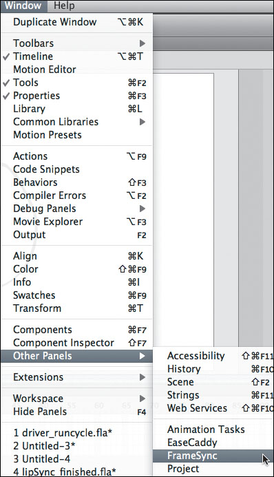
The FrameSync panel should now be displayed within Flash (Figure 2.145).
Figure 2.145 The FrameSync panel is now open for business.
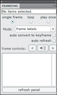
6. Select the “auto refresh” check box within the FrameSync panel (Figure 2.146).
Figure 2.146 Turn on the auto refresh option.
![]()
If you want to refresh the panel manually, you can click the Refresh Panel button at the bottom of the FrameSync panel.
The auto refresh setting automatically checks to see if your selection on Stage has changed. You can deselect this check box when you’re not using the FrameSync panel.
7. Update the Mode in the FrameSync panel to keyframes and select your symbol. You should now see all the frame numbers from within your mouth symbol listed in the FrameSync panel (Figure 2.147).
Figure 2.147 The FrameSync panel lists the mouth keyframe numbers.
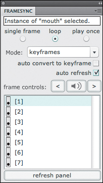
You can expand the FrameSync panel as needed to display all your mouth symbol frames without scrolling.
8. Add a keyframe (F6) on frame 5 of the mouth layer to begin lip syncing.
9. Click on the [5] item in the FrameSync panel and notice that your mouth symbol is now displaying the f/v mouth shape from frame 5 (Figure 2.148).
Figure 2.148 The mouth shape has been updated on the FrameSync panel.
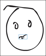
This feature prevents you from having to highlight the frame number in the Properties panel, type a new number, and press Return/Enter. You can accomplish the same task with a single click.
10. Normally, you’d have to scrub the Timeline to hear the audio. Click the button that looks like a speaker in the frame controls section of the FrameSync panel (Figure 2.149).
Figure 2.149 The Play Audio button in the frame controls allows you to play the current frame’s audio from the FrameSync panel.
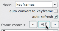
You should hear the audio from the current frame, just as if you’d scrubbed the playhead.
11. Select [2] in the FrameSync panel to set frame 5 to the “ah” mouth shape. Use the next frame (>) button in the FrameSync panel to navigate to the next frame.
12. Select the “auto convert to keyframe” check box to have FrameSync automatically create new keyframes for you when you change mouth shapes (within the FrameSync panel) on a new frame (Figure 2.150).
Figure 2.150 The “auto convert to keyframe” setting automatically creates new keyframes for you.
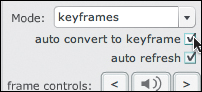
13. Click the Play Audio button to hear the audio on frame 6. Remember that this is the frame between “are” and “you” in the audio. Select [7] to set this frame to a new mouth position. Note that a new keyframe has automatically been created on frame 7.
14. Now that you’re getting an idea of how much time FrameSync can save you, save your current document and close it. There’s one more important FrameSync feature to try out.
So far, FrameSync has reduced the number of clicks needed to lip sync to a bare minimum. But it’s still up to you to keep track of which mouth shapes correspond to which frame numbers (which gets slower as you get more tired after hours of lip syncing). Remembering the frame numbers gets easier if you do a lot of lip syncing, and if you use the same frame numbers across all of your characters’ mouths. But FrameSync can relieve you of the need to memorize frame numbers entirely.
1. Reopen lipsync2.fla (the clean file) and save it as lipsync_labels.fla.
2. Double-click the mouth symbol on Stage to edit it.
3. Within the mouth symbol’s Timeline, create a new layer named labels.
5. Select the first keyframe of the labels layer. In the Properties panel, add a label Name of open (Figure 2.151).
Figure 2.151 Add a frame label using the Properties panel.
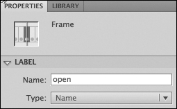
6. Select the second frame in the labels layer and create a blank keyframe (F7). Give this keyframe a label of ai, since this frame’s shape can be used for “ah” and “ai” sounds.
7. Repeat the previous step so that frames 3, 4, 5, 6, and 7 have values of eh, oh, fv, mbp, and closed, respectively (Figure 2.152).
Figure 2.152 Each mouth shape now has a corresponding label (as indicated by the red flags on the frames).
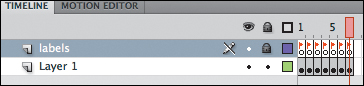
8. Optionally, you can select a frame on both the label and artwork (“Layer 1”) layers (Figure 2.153) and add frames (F5) until the label is readable on the Timeline.
Figure 2.153 Be sure to select the frame on both the artwork and label layers before adding frames; otherwise, the label and the mouth shape will end up on different frames.
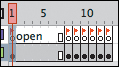
Repeat this step with each label/shape so that you can read every label on the Timeline (Figure 2.154).
Figure 2.154 Every label is now readable on the Timeline.
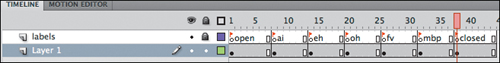
In Chapter 4 you’ll create a command that will automatically generate a Graphic symbol with these labels in place.
9. Return to the main Timeline by clicking Scene 1 in the top-left corner.
10. In the FrameSync panel, switch the Mode to frame labels. You should now see your labels in the FrameSync panel (Figure 2.155).
Figure 2.155 FrameSync displays the mouth symbol’s frame labels so you don’t have to memorize the frame numbers.
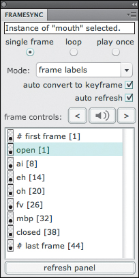
Warren Fuller, aka Animonger, also has a great extension for lip syncing called AnimSlider. A free version of AnimSlider and a couple of commercial versions are available at www.animonger.com/flashtools.html.
No more need to memorize frame numbers!
SmartMouth Extension
Justin also has a new lip syncing extension in the works called SmartMouth (Figure 2.156). In the SmartMouth dialog box, you can input your mouth shapes (as symbols, frame numbers, or frame labels) for the common phonemes, and SmartMouth will analyze your audio and place your mouth shapes right on the Timeline! SmartMouth is not meant to replace the animator. You’ll still have to make some adjustments by hand, but it should be a huge time-saver. The extension will probably cost about $45 for a single license. Check http://blog.ajarproductions.com for details on when SmartMouth will be released.
Figure 2.156 A preview of the SmartMouth extension interface.

The lip sync techniques demonstrated can also be used to animate other facial features and body parts. They can be particularly useful for animating eyes (Figure 2.157).
Figure 2.157 The FrameSync extension can be used to sync other parts (like eyes).
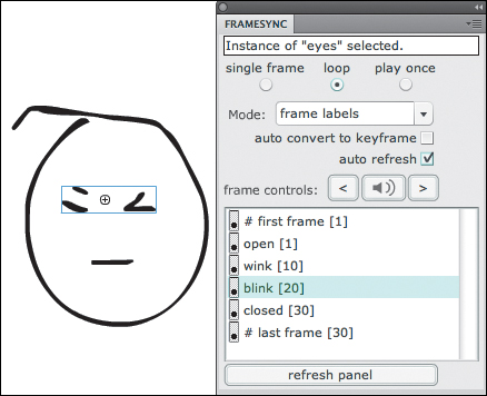
Now that you have a solid foundation in animating your character on the Timeline, Chapter 3 will illustrate how to animate your character with ActionScript. You’ll also learn how to create some powerful effects for the world that your character might inhabit.