
Chapter 12. Using Time and Dates
12.0. Introduction
Managing time is a fundamental element of interactive computing. This chapter covers built-in Arduino functions and introduces many additional techniques for handling time delays, time measurement, and real-world times and dates.
12.1. Creating Delays
Problem
You want your sketch to pause for some period of time. This may be some number of milliseconds, or a time given in seconds, minutes, hours, or days.
Solution
The Arduino delay function is used in many sketches throughout this book.
delay pauses a sketch for the
number of milliseconds specified as a parameter. (There are 1,000
milliseconds in one second.) The sketch that follows shows how you can use delay to get almost any interval:
/*
 * delay sketch
 */

const long oneSecond = 1000;  // a second is a thousand milliseconds
const long oneMinute = oneSecond * 60;
const long oneHour   = oneMinute * 60;
const long oneDay    = oneHour * 24;


void setup()
{
  Serial.begin(9600);
}

void loop()
{
  Serial.println("delay for 1 millisecond");
  delay(1);
  Serial.println("delay for 1 second");
  delay(oneSecond);
  Serial.println("delay for 1 minute");
  delay(oneMinute);
  Serial.println("delay for 1 hour");
  delay(oneHour);
  Serial.println("delay for 1 day");
  delay(oneDay);
  Serial.println("Ready to start over");
}
Discussion
The delay function has a
range from one one-thousandth of a second to around 25 days (just less
than 50 days if using an unsigned long variable type; see Chapter 2 for more on variable
types).
The delay function pauses the
execution of your sketch for the duration of the delay. If you need to
perform other tasks within the delay period, using millis, as explained
in Recipe 12.2, is more
suitable.
You can use delayMicroseconds to
delay short periods. There are 1,000 microseconds in one millisecond,
and 1 million microseconds in one second. delayMicroseconds will pause from one
microsecond to around 16 milliseconds, but for delays longer than a
few thousand microseconds you should use delay instead:
delayMicroseconds(10); // delay for 10 microseconds
Note
delay and delayMicroseconds will delay for at least
the amount of time given as the parameter, but they could delay a
little longer if interrupts occur within the delay time.
See Also
The Arduino reference for delay: http://www.arduino.cc/en/Reference/Delay
12.2. Using millis to Determine Duration
Problem
You want to know how much time has elapsed since an event happened; for example, how long a switch has been held down.
Solution
Arduino has a function named millis (short for milliseconds) that is used
in the following sketch to print how long a button was pressed (see
Recipe 5.2 for details
on how to connect the switch):
/*
  millisDuration sketch
  returns the number of milliseconds that a button has been pressed
 */

const int switchPin = 2;                   // the number of the input pin

long startTime; // the value returned from millis when the switch is pressed
long duration;  // variable to store the duration

void setup()
{
  pinMode(switchPin, INPUT);
  digitalWrite(switchPin, HIGH); // turn on pull-up resistor
  Serial.begin(9600);
}


void loop()
{
  if(digitalRead(switchPin) == LOW)
  {
     // here if the switch is pressed
     startTime = millis();
     while(digitalRead(switchPin) == LOW)
        ; // wait while the switch is still pressed
     long duration = millis() - startTime;
     Serial.println(duration);
  }
}
Discussion
The millis function returns
the number of milliseconds since the current sketch started
running.
Warning
The millis function will
overflow (go back to zero) after approximately
50 days. See Recipes 12.4 and 12.5 for information about using the
Time library for handling intervals from seconds to years.
By storing the start time for an event, you can determine the duration of the event by subtracting the start time from the current time, as shown here:
long duration = millis() - startTime;
You can create your own delay function using millis that can continue to do other things
while checking repeatedly to see if the delay period has passed. One
example of this can be found in the BlinkWithoutDelay example
sketch provided with the Arduino distribution. The following
fragments from that sketch explain the loop code:
void loop()
{
  // here is where you'd put code that needs to be running all the time...
The next line checks to see if the desired interval has passed:
  if (millis() - previousMillis > interval)
  {
    // save the last time you blinked the LED
If the interval has passed, the current millis value is saved in the variable
previousMillis:
    previousMillis = millis();

    // if the LED is off turn it on and vice versa:
    if (ledState == LOW)
      ledState = HIGH;
    else
      ledState = LOW;

    // set the LED with the ledState of the variable:
    digitalWrite(ledPin, ledState);
  }
}
Here is a way to package this logic into a function
named myDelay that will
delay the code in loop but can
perform some action during the delay period. You can customize the
functionality for your application, but in this example, an LED is
flashed five times per second even while the print statement in
loop is delayed for four-second
intervals:
// blink an LED for a set amount of time
const int ledPin =  13;         // the number of the LED pin

int ledState = LOW;             // ledState used to set the LED
long previousMillis = 0;        // will store last time LED was updated

void setup()
{
  pinMode(ledPin, OUTPUT);
  Serial.begin(9600);
}

void loop()
{
  Serial.println(millis() / 1000); // print elapsed seconds every four seconds
  // wait four seconds (but at the same time, quickly blink an LED)
  myDelay(4000);
}

// duration is delay time in milliseconds
void myDelay(unsigned long duration)
{
  unsigned long start = millis();
  while (millis() - start <= duration)
  {
    blink(100);  // blink the LED inside the while loop
  }
}


// interval is the time that the LED is on and off
void blink(long interval)
{
  if (millis() - previousMillis > interval)
  {
    // save the last time you blinked the LED
    previousMillis = millis();
    // if the LED is off turn it on and vice versa:
    if (ledState == LOW)
      ledState = HIGH;    else
      ledState = LOW;
    digitalWrite(ledPin, ledState);
  }
}
You can put code in the myDelay function for an action that you want
to happen repeatedly while the function waits for the specified time
to elapse.
Another approach is to use a third-party library available from the Arduino Playground, called TimedAction (http://www.arduino.cc/playground/Code/TimedAction):
#include <TimedAction.h>

//initialize a TimedAction class to change LED state every second.
TimedAction timedAction = TimedAction(NO_PREDELAY,1000,blink);


const int ledPin =  13;      // the number of the LED pin
boolean ledState = LOW;


void setup()
{
  pinMode(ledPin,OUTPUT);
  digitalWrite(ledPin,ledState);
}

void loop()
{
  timedAction.check();
}

void blink()
{
  if (ledState == LOW)
    ledState = HIGH;
  else
    ledState = LOW;

  digitalWrite(ledPin,ledState);
}
See Also
The Arduino reference for millis: http://www.arduino.cc/en/Reference/Millis
See Recipes 12.4 and 12.5 for information about using the Time library to handle intervals from seconds to years.
12.3. More Precisely Measuring the Duration of a Pulse
Problem
You want to determine the duration of a pulse with microsecond
accuracy; for example, to measure the exact duration of HIGH or LOW pulses on a pin.
Solution
The pulseIn function returns the duration in microseconds for a
changing signal on a digital pin. This sketch prints the time in
microseconds of the HIGH and
LOW pulses generated by analogWrite (see the section on Analog Output in Chapter 7).
Because the analogWrite pulses are
generated internally by Arduino, no external wiring is required:
/*
  PulseIn sketch
  displays duration of high and low pulses from analogWrite
 */


const int inputPin = 3;   // analog output pin to monitor
unsigned long val;  // this will hold the value from pulseIn

void setup()
{
  Serial.begin(9600);

  analogWrite(inputPin, 128);
  Serial.print("Writing 128 to pin ");
  Serial.print(inputPin);
  printPulseWidth(inputPin);

  analogWrite(inputPin, 254);
  Serial.print("Writing 254 to pin ");
  Serial.print(inputPin);
  printPulseWidth(inputPin);

}

void loop()
{
}

void printPulseWidth(int pin)
{
   val = pulseIn(pin, HIGH);
   Serial.print(": High Pulse width = ");
   Serial.print(val);
   val = pulseIn(pin, LOW);
   Serial.print(", Low Pulse width = ");
   Serial.println(val);
}
Discussion
The Serial monitor will display :
Writing 128 to pin 3: High Pulse width = 989, Low Pulse width = 997
Writing 254 to pin 3: High Pulse width = 1977, Low Pulse width = 8
pulseIn can measure how long
a pulse is either HIGH or LOW:
pulseIn(pin, HIGH); // returns microseconds that pulse is HIGH
pulseIn(pin, LOW)   // returns microseconds that pulse is LOW
The pulseIn function waits
for the pulse to start (or for a timeout if there is no pulse). By default, it will stop
waiting after one second, but you can change that by specifying the
time to wait in microseconds as a third parameter (note that 1,000
microseconds equals 1 millisecond):
pulseIn(pin, HIGH, 5000); // wait 5 milliseconds for the pulse to start
Note
The timeout value only matters if the pulse does not start within the given period. Once the start of a pulse is detected, the function will start timing and will not return until the pulse ends.
pulseIn can measure values
between around 10 microseconds to three minutes in duration, but the
value of long pulses may not be very accurate.
See Also
The Arduino reference for pulseIn: http://www.arduino.cc/en/Reference/PulseIn
Recipe 6.4 shows pulseIn used to measure the pulse width of
an ultrasonic distance sensor.
Recipe 18.2 provides more information on using hardware interrupts.
12.4. Using Arduino as a Clock
Problem
You want to use the time of day (hours, minutes, and seconds) in a sketch, and you don’t want to connect external hardware.
Solution
This sketch uses the Time library to display the time of day. The Time library can be downloaded from: http://www.arduino.cc/playground/Code/Time.
/*
 * Time sketch
 *
 */

#include <Time.h>


void setup()
{
  Serial.begin(9600);
  setTime(12,0,0,1,1,11); // set time to noon Jan 1 2011
}

void loop()
{
  digitalClockDisplay();
  delay(1000);
}

void digitalClockDisplay(){
  // digital clock display of the time
  Serial.print(hour());
  printDigits(minute());
  printDigits(second());
  Serial.print(" ");
  Serial.print(day());
  Serial.print(" ");
  Serial.print(month());
  Serial.print(" ");
  Serial.print(year());
  Serial.println();
}

void printDigits(int digits){
  // utility function for clock display: prints preceding colon and leading 0
  Serial.print(":");
  if(digits < 10)
    Serial.print('0'),
  Serial.print(digits);
}
Discussion
The Time library enables you to keep track of the date and time. Many Arduino boards use a quartz crystal
for timing, and this is accurate to a couple of seconds per day, but
it does not have a battery to remember the time when power is switched
off. Therefore, time will restart from 0 each time a sketch starts, so
you need to set the time using the setTime function.
The sketch sets the time to noon on January 1 each time it starts.
Note
The Time library uses a standard known as Unix (also called
POSIX) time. The values represent the number of elapsed seconds
since January 1, 1970. Experienced C programmers may recognize that
this is the same as the time_t
used in the ISO standard C library for storing time values.
Of course, it’s more useful to set the time to your current local time instead of a fixed value. The following sketch gets the numerical time value (the number of elapsed seconds since January 1, 1970) from the serial port to set the time. You can enter a value using the Serial Monitor (the current Unix time can be found on a number of websites using the Google search terms “Unix time convert”):
/*
 * TimeSerial sketch
 * example code illustrating Time library set through serial port messages.
 *
 * Messages consist of the letter T followed by ten digit time
 * (as seconds since Jan 1 1970)
 * You can send the text on the next line using Serial Monitor to set the
 * clock to noon Jan 1 2011:
 * T1293883200
 *
 * A Processing example sketch to automatically send the messages is
 * included in the Time library download
 */

#include <Time.h>

#define TIME_MSG_LEN  11   // time sync consists of a HEADER followed by ten
                           // ascii digits
#define TIME_HEADER  'T'   // Header tag for serial time sync message

void setup()  {
  Serial.begin(9600);
  Serial.println("Waiting for time sync message");
}

void loop(){
  if(Serial.available() )
  {
    processSyncMessage();
  }
  if(timeStatus()!= timeNotSet)
  {
    // here if the time has been set
    digitalClockDisplay();
  }
  delay(1000);
}

void digitalClockDisplay(){
  // digital clock display of the time
  Serial.print(hour());
  printDigits(minute());
  printDigits(second());
  Serial.print(" ");
  Serial.print(day());
  Serial.print(" ");
  Serial.print(month());
  Serial.print(" ");
  Serial.print(year());
  Serial.println();
}

void printDigits(int digits){
  // utility function for digital clock display: prints preceding colon
  // and leading 0
  Serial.print(":");
  if(digits < 10)
    Serial.print('0'),
  Serial.print(digits);
}

void processSyncMessage() {
  // if time sync available from serial port, update time and return true
  // time message consists of a header and ten ascii digits
  while(Serial.available() >=  TIME_MSG_LEN ){
    char c = Serial.read() ;
    Serial.print(c);
    if( c == TIME_HEADER ) {
      time_t pctime = 0;
      for(int i=0; i < TIME_MSG_LEN -1; i++){
        c = Serial.read();
        if( isDigit(c)) {
          pctime = (10 * pctime) + (c - '0') ; // convert digits to a number
        }
      }
      setTime(pctime);   // Sync clock to the time received on serial port
    }
  }
}
The code to display the time and date is the same as before, but now the sketch waits to receive the time from the serial port. See the Discussion in Recipe 4.3 if you are not familiar with how to receive numeric data using the serial port.
A processing sketch named SyncArduinoClock is included with the Time library examples (it’s in the
Time/Examples/Processing/SyncArduinoClock
folder). This Processing sketch will send the current time from your
computer to Arduino at the click of a mouse. Run SyncArduinoClock in
Processing, ensuring that the serial port is the one connected to
Arduino (Chapter 4 describes how to run
a Processing sketch that talks to Arduino). You should see the message
Waiting for time sync message sent
by Arduino and displayed in the
Processing text area (the black area for text messages at the bottom
of the Processing IDE). Click the Processing application window (it’s
a 200-pixel gray square) and you should see the text area display the
time as printed by the Arduino sketch.
You can also set the clock from the Serial Monitor if you can get the current Unix time; http://www.epochconverter.com/ is one of many websites that provide the time in this format. Copy the 10-digit number indicated as the current Unix time and paste this into the Serial Monitor Send window. Precede the number with the letter T and click Send. For example, if you send this:
T1282041639
Arduino should respond by displaying the time every second:
10:40:49 17 8 2010
10:40:50 17 8 2010
10:40:51 17 8 2010
10:40:52 17 8 2010
10:40:53 17 8 2010
10:40:54 17 8 2010
. . .
You can also set the time using buttons or other input devices such as tilt sensors, a joystick, or a rotary encoder.
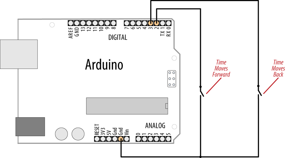
The following sketch uses two buttons to move the clock “hands” forward or backward. Figure 12-1 shows the connections (see Recipe 5.2 if you need help using switches):
/*
   AdjustClockTime sketch
   buttons on pins 2 and 3 adjust the time
 */

#include <Time.h>

const int  btnForward = 2;  // button to move time forward
const int  btnBack = 3;     // button to move time back

unsigned long  prevtime;   // when the clock was last displayed

void setup()
{
  digitalWrite(btnForward, HIGH);  // enable internal pull-up resistors
  digitalWrite(btnBack, HIGH);
  setTime(12,0,0,1,1,11); // start with the time set to noon Jan 1 2011
  Serial.begin(9600);
  Serial.println("ready");
}

void loop()
{
  prevtime = now();   // note the time
  while( prevtime == now() )    // stay in this loop till the second changes
  {
      // check if the set button pressed while waiting for second to roll over
     if(checkSetTime())
         prevtime = now();   // time changed so reset start time
  }
  digitalClockDisplay();
}

// functions checks to see if the time should be adjusted
// returns true if time was changed
boolean checkSetTime()
{
int step;   // the number of seconds to move (backwards if negative)
boolean isTimeAdjusted = false;  // set to true if the time is adjusted
  step = 1;   // ready to step forwards
  while(digitalRead(btnForward)== LOW)
  {
     adjustTime(step);
     isTimeAdjusted = true; // to tell the user that the time has changed
     step = step + 1; // next step will be bigger
     digitalClockDisplay(); // update clock
     delay(100);
  }
  step = -1;   // negative numbers step backwards
  while(digitalRead(btnBack)== LOW)
  {
     adjustTime(step);
     isTimeAdjusted = true; // to tell the user that the time has changed
     step = step - 1; // next step will be a bigger negative number
     digitalClockDisplay(); // update clock
     delay(100);
  }
  return isTimeAdjusted;  // tell the user if the time was adjusted
}

void digitalClockDisplay(){
  // digital clock display of the time
  Serial.print(hour());
  printDigits(minute());
  printDigits(second());
  Serial.print(" ");
  Serial.print(day());
  Serial.print(" ");
  Serial.print(month());
  Serial.print(" ");
  Serial.print(year());
  Serial.println();
}

void printDigits(int digits){
  // utility function for clock display: prints preceding colon and leading 0
  Serial.print(":");
  if(digits < 10)
    Serial.print('0'),
  Serial.print(digits);
}
The sketch uses the same digitalClockDisplay
and printDigits functions from
Recipe 12.3, so copy
those prior to running the sketch.
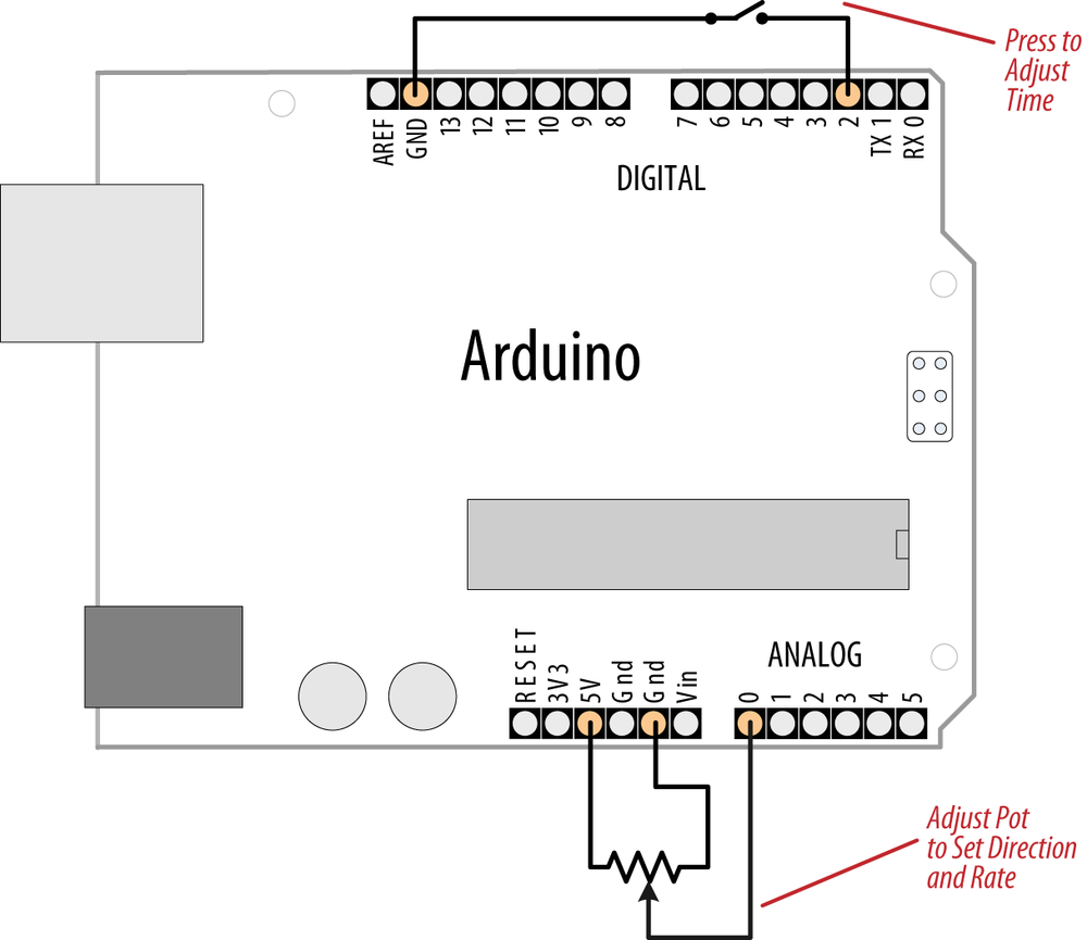
Here is a variation on this sketch that uses the position of a variable resistor to determine the direction and rate of adjustment when a switch is pressed:
#include <Time.h>

const int  potPin = 0;     // pot to determine direction and speed
const int  buttonPin = 2;  // button enables time adjustment

unsigned long  prevtime;   // when the clock was last displayed

void setup()
{
  digitalWrite(buttonPin, HIGH);  // enable internal pull-up resistors
  setTime(12,0,0,1,1,11); // start with the time set to noon Jan 1 2011
  Serial.begin(9600);
}

void loop()
{
  prevtime = now();   // note the time
  while( prevtime == now() )    // stay in this loop till the second changes
  {
      // check if the set button pressed while waiting for second to roll over
     if(checkSetTime())
         prevtime = now();   //  time changed so reset start time
  }
  digitalClockDisplay();
}

// functions checks to see if the time should be adjusted
// returns true if time was changed
boolean checkSetTime()
{
int value;  // a value read from the pot
int step;   // the number of seconds to move (backwards if negative)
boolean isTimeAdjusted = false;  // set to true if the time is adjusted

  while(digitalRead(buttonPin)== LOW)
  {
    // here while button is pressed
     value = analogRead(potPin);  // read the pot value
     step = map(value, 0,1023, 10, -10);  // map value to the desired range
     if( step != 0)
     {
        adjustTime(step);
        isTimeAdjusted = true; // to tell the user that the time has changed
        digitalClockDisplay(); // update clock
        delay(100);
     }
  }
  return isTimeAdjusted;
}
The preceding sketch uses the same digitalClockDisplay and printDigits functions from Recipe 12.3, so copy those
prior to running the sketch. Figure 12-2 shows how the
variable resistor and switch are connected.
All these examples print to the serial port, but you can print the output to LEDs or LCDs. The download for the Graphical LCD covered in Recipe 11.9 contains example sketches for displaying and setting time using an analog clock display drawn on the LCD.
The Time library includes convenience functions for converting to and from various time formats. For example, you can find out how much time has elapsed since the start of the day and how much time remains until the day’s end.
You can look in Time.h in the libraries folder for the complete list. More details are available in Chapter 16:
dayOfWeek( now() );           // the day of the week (Sunday is day 1)
elapsedSecsToday( now() );    // returns the number of seconds since the start
                              // of today
nextMidnight( now() );        // how much time to the end of the day
elapsedSecsThisWeek( now() ); // how much time has elapsed since the start of
                              // the week
You can also print text strings for the days and months; here is a variation on the digital clock display code that prints the names of the day and month:
void digitalClockDisplay(){
  // digital clock display of the time
  Serial.print(hour());
  printDigits(minute());
  printDigits(second());
  Serial.print(" ");
  Serial.print(dayStr(weekday())); // print the day of the week
  Serial.print(" ");
  Serial.print(day());
  Serial.print(" ");
  Serial.print(monthShortStr(month())); // print the month (abbreviated)
  Serial.print(" ");
  Serial.print(year());
  Serial.println();
}
See Also
Arduino Time library reference: http://www.arduino.cc/playground/Code/Time
Wikipedia article on Unix time: http://en.wikipedia.org/wiki/Unix_time
http://www.epochconverter.com/ and http://www.onlineconversion.com/unix_time.htm are two popular Unix time conversion tools.
12.5. Creating an Alarm to Periodically Call a Function
Solution
TimeAlarms is a companion library included in the Time library download discussed in Recipe 12.4 (installing the Time library will also install the TimeAlarms library). TimeAlarms makes it easy to create time and date alarms:
/*
 * TimeAlarmsExample sketch
 *
 * This example calls alarm functions at 8:30 am and at 5:45 pm (17:45)
 * and simulates turning lights on at night and off in the morning
 *
 * A timer is called every 15 seconds
 * Another timer is called once only after 10 seconds
 *
 * At startup the time is set to Jan 1 2010  8:29 am
 */

#include <Time.h>
#include <TimeAlarms.h>

void setup()
{
  Serial.begin(9600);
  Serial.println("TimeAlarms Example");
  Serial.println("Alarms are triggered daily at 8:30 am and 17:45 pm");
  Serial.println("One timer is triggered every 15 seconds");
  Serial.println("Another timer is set to trigger only once after 10 seconds");
  Serial.println();

  setTime(8,29,40,1,1,10); // set time to 8:29:40am Jan 1 2010

  Alarm.alarmRepeat(8,30,0, MorningAlarm);  // 8:30am every day
  Alarm.alarmRepeat(17,45,0,EveningAlarm);  // 5:45pm every day

  Alarm.timerRepeat(15, RepeatTask);            // timer for every 15 seconds
  Alarm.timerOnce(10, OnceOnlyTask);            // called once after 10 seconds
}

void MorningAlarm()
{
  Serial.println("Alarm: - turn lights off");
}

void EveningAlarm()
{
  Serial.println("Alarm: - turn lights on");
}

void RepeatTask()
{
  Serial.println("15 second timer");
}

void OnceOnlyTask()
{
  Serial.println("This timer only triggers once");
}

void  loop()
{
  digitalClockDisplay();
  Alarm.delay(1000); // wait one second between clock display
}

void digitalClockDisplay()
{
  // digital clock display of the time
  Serial.print(hour());
  printDigits(minute());
  printDigits(second());
  Serial.println();
}

// utility function for digital clock display: prints preceding colon and
// leading 0.
//
void printDigits(int digits)
{
  Serial.print(":");
  if(digits < 10)
    Serial.print('0'),
  Serial.print(digits);
}
Discussion
You can schedule tasks to trigger at a particular time of day (these are called alarms) or schedule tasks to occur after an interval of time has elapsed (called timers). Each of these tasks can be created to continuously repeat or to occur only once.
To specify an alarm to trigger a task repeatedly at a particular time of day use:
Alarm.alarmRepeat(8,30,0, MorningAlarm);
This calls the function MorningAlarm at 8:30
a.m. every day.
If you want the alarm to trigger only once, you can use the
alarmOnce method:
Alarm.alarmOnce(8,30,0, MorningAlarm);
This calls the function MorningAlarm a single time only (the next
time it is 8:30 a.m.) and will not trigger again.
Timers trigger tasks that occur after a specified interval of time has passed rather than at a specific time of day. The timer interval can be specified in any number of seconds, or in hour, minutes, and seconds:
Alarm.timerRepeat(15, Repeats); // timer task every 15 seconds
This calls the Repeats function in
your sketch every 15 seconds.
If you want a timer to trigger once only, use the timerOnce method:
Alarm.timerOnce(10, OnceOnly); // called once after 10 seconds
This calls the onceOnly
function in a sketch 10 seconds after the timer is
created.
Note
Your code needs to call Alarm.delay regularly because this
function checks the state of all the scheduled events. Failing to
regularly call Alarm.delay will
result in the alarms not being triggered. You can call Alarm.delay(0) if you need to service the
scheduler without a delay. Always use Alarm.delay instead of delay when using TimeAlarms in a
sketch.
The TimeAlarms library requires the Time library to be installed—see Recipe 12.4. No internal or external hardware is required to use the TimeAlarms library. The scheduler does not use interrupts, so the task-handling function is the same as any other functions you create in your sketch (code in an interrupt handler has restrictions that are discussed in Chapter 18, but these do not apply to TimeAlarms functions).
Timer intervals can range from one second to several years. (If you need timer intervals shorter than one second, the TimedAction library by Alexander Brevig may be more suitable; see http://www.arduino.cc/playground/Code/TimedAction.)
Tasks are scheduled for specific times designated by the system
clock in the Time library (see Recipe 12.4 for more details). If you change
the system time (e.g., by calling setTime), the trigger times are not
adjusted. For example, if you use setTime to move one
hour ahead, all alarms and timers will occur one hour sooner. In other
words, if it’s 1:00 and a task is set to trigger in two hours (at
3:00), and then you change the current time to 2:00, the task will
trigger in one hour. If the system time is set backward—for example,
to 12:00—the task will trigger in three hours (i.e., when the system
time indicates 3:00). If the time is reset to earlier than the time at
which a task was scheduled, the task will be triggered immediately
(actually, on the next call to Alarm.delay).
This is the expected behavior for alarms—tasks are scheduled for a specific time of day and will trigger at that time—but the effect on timers may be less clear. If a timer is scheduled to trigger in five minutes’ time and then the clock is set back by one hour, that timer will not trigger until one hour and five minutes have elapsed (even if it is a repeating timer—a repeat does not get rescheduled until after it triggers).
Up to six alarms and timers can be scheduled to run at the same time. You can modify the library to enable more tasks to be scheduled; Recipe 16.3 shows you how to do this.
onceOnly alarms and timers
are freed when they are triggered, and you can reschedule these as
often as you want so long as there are no more than six pending at one
time. The following code gives one example of how a timerOnce task can be rescheduled:
Alarm.timerOnce(random(10), randomTimer);  // trigger after random
                                           // number of seconds

void randomTimer(){
  int period = random(2,10);             // get a new random period
  Alarm.timerOnce(period, randomTimer);  // trigger for another random period
}
12.6. Using a Real-Time Clock
Problem
You want to use the time of day provided by a real-time clock (RTC). External boards usually have battery backup, so the time will be correct even when Arduino is reset or turned off.
Solution
The simplest way to use an RTC is with a companion library for the Time library, named DS1307RTC.h. This recipe is for the widely used DS1307 and DS1337 RTC chips:
/*
* TimeRTC sketch
* example code illustrating Time library with real-time clock.
*
*/
#include <Time.h>
#include <Wire.h>
#include <DS1307RTC.h> // a basic DS1307 library that returns time as a time_t
void setup() {
Serial.begin(9600);
setSyncProvider(RTC.get); // the function to get the time from the RTC
if(timeStatus()!= timeSet)
Serial.println("Unable to sync with the RTC");
else
Serial.println("RTC has set the system time");
}
void loop()
{
digitalClockDisplay();
delay(1000);
}
void digitalClockDisplay(){
// digital clock display of the time
Serial.print(hour());
printDigits(minute());
printDigits(second());
Serial.print(" ");
Serial.print(day());
Serial.print(" ");
Serial.print(month());
Serial.print(" ");
Serial.print(year());
Serial.println();
}
// utility function for digital clock display: prints preceding colon and
// leading 0.
//
void printDigits(int digits){
Serial.print(":");
if(digits < 10)
Serial.print('0'),
Serial.print(digits);
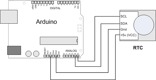
}Most RTC boards for Arduino use the I2C protocol for communicating (see Chapter 13 for more on I2C). Connect the line marked “SCL” (or “Clock”) to Arduino analog pin 5 and “SDA” (or “Data”) to analog pin 4, as shown in Figure 12-3. (Analog pins 4 and 5 are used for I2C; see Chapter 13). Take care to ensure that you connect the +5V power line and Gnd pins correctly.
Discussion
The code is similar to other recipes using the Time library, but it gets its value from the RTC rather than from the serial port or hardcoded value. The only additional line needed is this:
setSyncProvider(RTC.get); // the function to get the time from the RTC
The setSyncProvider
function tells the Time library how it should get information for
setting (and updating) the time. RTC.get is a method within the RTC library
that returns the current time in the format used by the Time library
(Unix time).
Each time Arduino starts, the setup function will call RTC.get to set the time from the RTC
hardware.
Before you can get the correct time from the module, you need to set its time. Here is a sketch that enables you to set the time on the RTC hardware—you only need to do this when you first attach the battery to the RTC, when replacing the battery, or if the time needs to be changed:
/*
 * TimeRTCSet sketch
 * example code illustrating Time library with real-time clock.
 *
 * RTC is set in response to serial port time message
 * A Processing example sketch to set the time is included in the download
 */

#include <Time.h>
#include <Wire.h>
#include <DS1307RTC.h>  // a basic DS1307 library that returns time as a time_t

void setup()  {
  Serial.begin(9600);
  setSyncProvider(RTC.get);   // the function to get the time from the RTC
  if(timeStatus()!= timeSet)
     Serial.println("Unable to sync with the RTC");
  else
     Serial.println("RTC has set the system time");
}

void loop()
{
  if(Serial.available())
  {
     time_t t = processSyncMessage();
     if(t >0)
     {
        RTC.set(t);   // set the RTC and the system time to the received value
        setTime(t);
     }
  }
   digitalClockDisplay();
   delay(1000);
}

void digitalClockDisplay(){
  // digital clock display of the time
  Serial.print(hour());
  printDigits(minute());
  printDigits(second());
  Serial.print(" ");
  Serial.print(day());
  Serial.print(" ");
  Serial.print(month());
  Serial.print(" ");
  Serial.print(year());
  Serial.println();
}

// utility function for digital clock display: prints preceding colon and
// leading 0.
//
void printDigits(int digits){
  Serial.print(":");
  if(digits < 10)
    Serial.print('0'),
  Serial.print(digits);
}

/*  code to process time sync messages from the serial port   */
#define TIME_MSG_LEN  11   // time sync to PC is HEADER followed by Unix time_t
                           // as ten ascii digits
#define TIME_HEADER  'T'   // Header tag for serial time sync message

time_t processSyncMessage() {
  // return the time if a valid sync message is received on the serial port.
  // time message consists of a header and ten ascii digits
  while(Serial.available() >=  TIME_MSG_LEN ){
    char c = Serial.read() ;
    Serial.print(c);
    if( c == TIME_HEADER ) {
      time_t pctime = 0;
      for(int i=0; i < TIME_MSG_LEN -1; i++){
        c = Serial.read();
        if( c >= '0' && c <= '9'){
          pctime = (10 * pctime) + (c - '0') ; // convert digits to a number
        }
      }
      return pctime;
    }
  }
  return 0;
}
This sketch is almost the same as the TimeSerial sketch in Recipe 12.4 for setting the time from the serial port, but here the following function is called when a time message is received from the computer to set the RTC:
 RTC.set(t);   // set the RTC and the system time to the received value

 setTime(t);
The RTC chip uses I2C to communicate with Arduino. I2C is explained in Chapter 13; see Recipe 13.3 if you are interested in more details on I2C communication with the RTC chip.
See Also
The SparkFun BOB-00099 data sheet: http://store.gravitech.us/i2crecl.html