
Chapter 18. Using the Controller Chip Hardware
18.0. Introduction
The Arduino platform simplifies programming by providing easy-to-use function calls to hide complex, low-level hardware functions. But some applications need to bypass the friendly access functions to get directly at hardware, either because that’s the only way to get the needed functionality or because higher performance is required. This chapter shows how to access and use hardware functions that are not fully exposed through the documented Arduino language.
Note
Changing register values can change the behavior of some Arduino
functions (e.g., millis). The
low-level capabilities described in this chapter require care,
attention, and testing if you want your code to function
correctly.
Registers
Registers are variables that refer to hardware memory locations. They are used by the chip to configure hardware functions or for storing the results of hardware operations. The contents of registers can be read and written by your sketch. Changing register values will change the way the hardware operates, or the state of something (such as the output of a pin). Some registers represent a numerical value (the number a timer will count to). Registers can control or report on hardware status; for example, the state of a pin or if an interrupt has occurred. Registers are referenced in code using their names—these are documented in the data sheet for the microcontrollers. Setting a register to a wrong value usually results in a sketch functioning incorrectly, so carefully check the documentation to ensure that you are using registers correctly.
Interrupts
Interrupts are signals that enable the controller chip to stop the normal flow
of a sketch and handle a task that requires immediate attention before
continuing with what it was doing. Arduino core software uses
interrupts to handle incoming data from the serial port, to maintain
the time for the delay and millis functions, and to trigger the
attachInterrupt
function. Libraries, such as Wire and Servo, use interrupts when
an event occurs, so the code doesn’t have to constantly check to see
if the event has happened. This constant checking, called polling, can complicate the logic
of your sketch. Interrupts can be a reliable way to detect signals of
very short duration. Recipe 18.2
explains how to use interrupts to determine if a digital pin has
changed state.
Two or more interrupts may occur before the handling of the first interrupt is completed; for example, if two switches are pressed at the same time and each generates a different interrupt. The interrupt handler for the first switch must be completed before the second interrupt can get started. Interrupts should be brief, because an interrupt routine that takes too much time can cause other interrupt handlers to be delayed or to miss events.
Note
Arduino services one interrupt at a time. It suspends pending interrupts while it deals with an interrupt that has happened. Code to handle interrupts (called the interrupt handler, or interrupt service routine) should be brief to prevent undue delays to pending interrupts. An interrupt routine that takes too much time can cause other interrupt handlers to miss events. Activities that take a relatively long time, such as blinking an LED or even serial printing, should be avoided in an interrupt handler.
Timers
A standard Arduino board has three hardware timers for managing time-based tasks (the Mega has six). The timers are used in a number of Arduino functions:
Note
The Servo library uses the same timer as analogWrite on pins 9 and 10, so you can’t
use analogWrite with these pins
when using the Servo library.
The Mega has three additional 16-bit timers and uses different pin
numbers with analogWrite:
- Timer0
analogWritefunctions on pins 4 and 13- Timer1
analogWritefunctions on pins 11 and 12- Timer2
analogWritefunctions on pins 9 and 10- Timer3
analogWritefunctions on pins 2, 3, and 5- Timer4
analogWritefunctions on pins 6, 7, and 8- Timer5
analogWritefunctions on pins 45 and 46
Timers are counters that count pulses from a time source, called a timebase. The timer hardware consists of 8-bit or 16-bit digital counters that can be programmed to determine the mode the timer uses to count. The most common mode is to count pulses from the timebase on the Arduino board, usually 16 MHz derived from a crystal; 16 MHz pulses repeat every 62.5 nanoseconds, and this is too fast for many timing applications, so the timebase rate is reduced by a divider called a prescaler. Dividing the timebase by 8, for example, increases the duration of each count to half a microsecond. For applications in which this is still too fast, other prescale values can be used (see Table 18-1).
Timer operation is controlled by values held in registers that can be read and written by Arduino code. The values in these registers set the timer frequency (the number of system timebase pulses between each count) and the method of counting (up, down, up and down, or using an external signal).
Here is an overview of the timer registers (n is the timer number):
- Timer Counter Control Register A (TCCRnA)
Determines the operating mode
- Timer Counter Control Register B (TCCRnB)
Determines the prescale value
- Timer Counter Register (TCNTn)
Contains the timer count
- Output Compare Register A (OCRnA)
Interrupt can be triggered on this count
- Output Compare Register B (OCRnB)
Interrupt can be triggered on this count
- Timer/Counter Interrupt Mask Register (TIMSKn)
Sets the conditions for triggering an interrupt
- Timer/Counter 0 Interrupt Flag Register (TIFRn)
Indicates if the trigger condition has occurred
Table 18-1 is an overview of the bit values used to set the timer precision. Details of the functions of the registers are explained in the recipes where they are used.
Prescale factor | CSx2, CSx1, CSx0 | Precision | Time to overflow | |
8-bit timer | 16-bit timer | |||
1 | B001 | 62.5 ns | 16 µs | 4.096 ms |
8 | B010 | 500 ns | 128 µs | 32.768 ms |
64 | B011 | 4 µs | 1,024 µs | 262.144 ms |
256 | B100 | 16 µs | 4,096 µs | 1048.576 ms |
1,024 | B101 | 64 µs | 16,384 µs | 4194.304 ms |
B110 | External clock, falling edge | |||
B111 | External clock, rising edge | |||
All timers are initialized for a prescale of 64.
Precision in nanoseconds is equal to the CPU period (time for one CPU cycle) multiplied by the prescale.
Analog and Digital Pins
Chapter 5 described the standard Arduino functions to read and write (to/from) digital and analog pins. This chapter explains how you can control pins faster than using the Arduino read and write functions and make changes to analog methods to improve performance.
Some of the code in this chapter is more difficult to understand than the other recipes in this book, as it is moving beyond Arduino syntax and closer to the underlying hardware. These recipes work directly with the tersely named registers in the chip and use bit shifting and masking to manipulate bits in them. The benefit from this complexity is enhanced performance and functionality.
See Also
Overview of hardware resources: http://code.google.com/p/arduino/wiki/HardwareResourceMap
Timer1 (and Timer3) library: http://www.arduino.cc/playground/Code/Timer1
Tutorial on timers and PWM: http://arduino.cc/en/Tutorial/SecretsOfArduinoPWM
The Atmel ATmega 168/328 data sheets: http://www.atmel.com/dyn/resources/prod_documents/doc8271.pdf
Atmel application note on how to set up and use timers: http://www.atmel.com/dyn/resources/prod_documents/DOC2505.PDF
A thorough summary of information covering 8-bit timers: http://www.cs.mun.ca/~rod/Winter2007/4723/notes/timer0/timer0.html
Diagrams showing register settings for timer modes: http://web.alfredstate.edu/weimandn/miscellaneous/atmega168_subsystem/atmega168_subsystem_index.html
Wikipedia article on interrupts: http://en.wikipedia.org/wiki/Interrupts
18.1. Storing Data in Permanent EEPROM Memory
Solution
Use the EEPROM library to read and write values in EEPROM memory. This sketch blinks an LED using values read from EEPROM and allows the values to be changed using the Serial Monitor:
/*
  based on Blink without Delay
  uses EEPROM to store blink values
 */

#include <EEPROM.h>

// these values are saved in EEPROM
const byte EEPROM_ID = 0x99;   // used to identify if valid data in EEPROM
byte ledPin =  13;             // the number of the LED pin
int interval = 1000;           // interval at which to blink (milliseconds)

// variables that do not need to be saved
int ledState = LOW;             // ledState used to set the LED
long previousMillis = 0;        // will store last time LED was updated

//constants used to identify EEPROM addresses
const int ID_ADDR = 0;       // the EEPROM address used to store the ID
const int PIN_ADDR = 1;      // the EEPROM address used to store the pin
const int INTERVAL_ADDR = 2; // the EEPROM address used to store the interval

void setup()
{
  Serial.begin(9600);
  byte id = EEPROM.read(ID_ADDR); // read the first byte from the EEPROM
  if( id == EEPROM_ID)
  {
    // here if the id value read matches the value saved when writing eeprom
    Serial.println("Using data from EEPROM");
    ledPin = EEPROM.read(PIN_ADDR);
    byte hiByte =  EEPROM.read(INTERVAL_ADDR);
    byte lowByte =  EEPROM.read(INTERVAL_ADDR+1);
    interval =  word(hiByte, lowByte); // see word function in Recipe 3.15
  }
  else
  {
    // here if the ID is not found, so write the default data
    Serial.println("Writing default data to EEPROM");
    EEPROM.write(ID_ADDR,EEPROM_ID); // write the ID to indicate valid data
    EEPROM.write(PIN_ADDR, ledPin); // save the pin in eeprom
    byte hiByte = highByte(interval);
    byte loByte = lowByte(interval);
    EEPROM.write(INTERVAL_ADDR, hiByte);
    EEPROM.write(INTERVAL_ADDR+1, loByte);

  }
  Serial.print("Setting pin to ");
  Serial.println(ledPin,DEC);
  Serial.print("Setting interval to ");
  Serial.println(interval);

  pinMode(ledPin, OUTPUT);
}

void loop()
{
  // this is the same code as the BlinkWithoutDelay example sketch
  if (millis() - previousMillis > interval)
  {
    previousMillis = millis();     // save the last time you blinked the LED
    // if the LED is off turn it on and vice versa:
    if (ledState == LOW)
      ledState = HIGH;
    else
      ledState = LOW;
    digitalWrite(ledPin, ledState);   // set LED using value of ledState
  }
  processSerial();
}

// function to get duration or pin values from Serial Monitor
// value followed by  i is interval, p is pin number
int value = 0;

void processSerial()
{
   if( Serial.available())
  {
    char ch = Serial.read();
    if(ch >= '0' && ch <= '9') // is this an ascii digit between 0 and 9?
    {
       value = (value * 10) + (ch - '0'), // yes, accumulate the value
    }
    else if (ch == 'i')  // is this the interval
    {
       interval = value;
       Serial.print("Setting interval to ");
       Serial.println(interval);
       byte hiByte = highByte(interval);
       byte loByte = lowByte(interval);
       EEPROM.write(INTERVAL_ADDR, hiByte);
       EEPROM.write(INTERVAL_ADDR+1, loByte);
       value = 0; // reset to 0 ready for the next sequence of digits
    }
    else if (ch == 'p')  // is this the pin number
    {
       ledPin = value;
       Serial.print("Setting pin to ");
       Serial.println(ledPin,DEC);
       pinMode(ledPin, OUTPUT);
       EEPROM.write(PIN_ADDR, ledPin); // save the pin in eeprom
       value = 0; // reset to 0 ready for the next sequence of digits
    }
  }
}
Open the Serial Monitor. As the sketch starts, it tells you whether it is using values previously saved to EEPROM or defaults, if this is the first time the sketch is started.
You can change values by typing a number followed by a letter to indicate the action. A number followed by the letter i changes the blink interval; a number followed by a p changes the pin number for the LED.
Discussion
Arduino contains EEPROM memory that will store values even when power is switched off. There are 512 bytes of EEPROM in a standard Arduino board, 4K bytes in a Mega.
The sketch uses the EEPROM library to read and write values in EEPROM memory.
Once the library is included in the sketch, an EEPROM object is
available that accesses the memory. The library provides methods to
read, write, and clear. EEPROM.clear() is not used in this sketch because it erases all the
EEPROM memory.
The EEPROM library requires you to specify the address in memory that you want to read or write. This means you need to keep track of where each value is written so that when you access the value it is from the correct address.
To write a value, you use EEPROM.write(address, value). The address is
from 0 to 511 (on a standard Arduino board), and the value is a single
byte.
To read, you use EEPROM.read(address). The byte content of
that memory address is returned.
The sketch stores three values in EEPROM. The first value stored
is an ID value that is used only in
setup to identify if the EEPROM has
been previously written with valid data. If the value stored matches
the expected value, the other variables are read from EEPROM and used
in the sketch. If it doesn’t match, this sketch has not been run on
this board (otherwise, the ID would
have been written), so the default values are written, including the
ID value.
The sketch monitors the serial port, and new values received are written to EEPROM.
The sketch stores the ID
value in EEPROM address 0, the pin number in address 1, and the two
bytes for the interval start in address 2. The following line writes
the pin number to EEPROM. The variable ledPin is a byte, so it fits into a single
EEPROM address:
EEPROM.write(PIN_ADDR, ledPin); // save the pin in eeprom
Because interval is an int,
it requires two bytes of memory to store the value:
byte hiByte = highByte(interval);
byte loByte = lowByte(interval);
EEPROM.write(INTERVAL_ADDR, hiByte);
EEPROM.write(INTERVAL_ADDR+1, loByte);
The preceding code splits the value into two bytes that are stored in two consecutive addresses. Any additional variables to be added to EEPROM would need to be placed in addresses that follow these two bytes.
Here is the code used to rebuild the int variable from EEPROM:
ledPin = EEPROM.read(PIN_ADDR);
byte hiByte =  EEPROM.read(INTERVAL_ADDR);
byte lowByte =  EEPROM.read(INTERVAL_ADDR+1);
interval =  word(hiByte, lowByte);
See Chapter 3 for more on
using the word expression to create
an integer from two bytes.
For more complicated use of EEPROM, it is advisable to draw out a map of what is being saved where, to ensure that no address is used by more than one value, and that multibyte values don’t overwrite other information.
See Also
Recipe 3.14 provides more information on converting 16- and 32-bit values into bytes.
18.2. Using Hardware Interrupts
Problem
You want to perform some action when a digital pin changes value and you don’t want to have to constantly check the pin state.
Solution
This sketch monitors pulses on pin 2 and stores the duration in an array. When the array has been filled (64 pulses have been received), the duration of each pulse is displayed on the Serial Monitor:
/*
  Interrupts sketch
  see Recipe 10.1 for connection diagram
 */

const int irReceiverPin = 2;         // pin the receiver is connected to
const int numberOfEntries = 64;      // set this number to any convenient value

volatile unsigned long microseconds;
volatile byte index = 0;
volatile unsigned long results[numberOfEntries];

void setup()
{
  pinMode(irReceiverPin, INPUT);
  Serial.begin(9600);
  attachInterrupt(0, analyze, CHANGE);  // encoder pin on interrupt 0 (pin 2);
  results[0]=0;
}

void loop()
{
  if(index >= numberOfEntries)
  {
    Serial.println("Durations in Microseconds are:") ;
    for( byte i=0; i < numberOfEntries; i++)
    {
      Serial.println(results[i]);
    }
    index = 0; // start analyzing again
  }
  delay(1000);
}

void analyze()
{
  if(index < numberOfEntries  )
  {
    if(index > 0)
    {
      results[index] = micros() - microseconds;
    }
    index = index + 1;
  }
  microseconds = micros();
}
If you have an infrared receiver module, you can use the wiring in Recipe 10.1 to measure the pulse width from an infrared remote control. You could also use the wiring in Recipe 6.12 to measure pulses from a rotary encoder or connect a switch to pin 2 (see Recipe 5.1) to test with a push button.
Discussion
In setup, the attachInterrupt(0, analyze,
CHANGE); call enables the sketch to handle interrupts. The
first number in the call specifies which interrupt to initialize. On a
standard Arduino board, two interrupts are available: number 0,
which uses pin 2, and number 1 on pin 3. The Mega has four more:
number 2, which uses pin 21, number 3 on pin 20, number 4 on pin 19,
and number 5 on pin 18.
The next parameter specifies what function to call (sometimes
called an interrupt handler) when the
interrupt event happens; analyze in
this sketch.
The final parameter specifies what should trigger the interrupt.
CHANGE means whenever the pin level
changes (goes from low to high, or high to low). The other options
are:
LOWWhen the pin is low
RISINGWhen the pin goes from low to high
FALLINGWhen the pin goes from high to low
When reading code that uses interrupts, bear in mind that it may not be obvious when values in the sketch change because the sketch does not directly call the interrupt handler; it’s called when the interrupt conditions occur.
In this sketch, the main loop
checks the index variable to see if
all the entries have been set by the interrupt handler. Nothing in
loop changes the value of index. index is changed inside the analyze function when the interrupt
condition occurs (pin 2 changing state). The index value is used to store the time since
the last state change into the next slot in the results array. The time is calculated by
subtracting the last time the state changed from the current time in
microseconds. The current time is then saved as the last time a change
happened. (Chapter 12 describes this
method for obtaining elapsed time using the millis function; here micros is used to get elapsed microseconds
instead of milliseconds.)
The variables that are changed in an interrupt function are
declared as volatile; this lets
the compiler know that the values could change at any time (by an
interrupt handler). Without using the volatile keyword, the compiler would may
store the values in registers that can be accidentally overwritten by
an interrupt handler. To prevent this, the volatile keyword tells the compiler to store
the values in RAM rather than registers.
Each time an interrupt is triggered, index is incremented and the current time is
saved. The time difference is calculated and saved in the array
(except for the first time the interrupt is triggered, when index is 0). When the maximum number of entries has
occurred, the inner block in loop
runs, and it prints out all the values to the serial port. The code
stays in the while loop at the end
of the inner block, so you need to reset the board when you want to do
another run.
See Also
Recipe 6.12 has an example of external interrupts used to detect movement in a rotary encoder.
18.3. Setting Timer Duration
Problem
You want to do something at periodic intervals, and you don’t want to have your code constantly checking if the interval has elapsed. You would like to have a simple interface for setting the period.
Solution
The easiest way to use a timer is through a library. The following sketch uses the MsTimer2 library (http://www.arduino.cc/playground/Main/MsTimer2) to generate a pulse with a period that can be set using the Serial Monitor. This sketch flashes pin 13 at a rate that can be set using the Serial Monitor:
/*
  pulseTimer2
  pulse a pin at a rate set from serial input
 */

#include <MsTimer2.h>

const int pulsePin = 13;
const int NEWLINE = 10; // ASCII value for newline

int period = 100; // 10 milliseconds
boolean output = HIGH; // the state of the pulse pin

void setup()
{
  pinMode(pulsePin, OUTPUT);
  Serial.begin(9600);

  MsTimer2::set(period/2, flash);
  MsTimer2::start();

  period= 0; // reset to zero, ready for serial input
}

void loop()
{
   if( Serial.available())
  {
    char ch = Serial.read();
    if( isDigit(ch) ) // is this an ascii digit between 0 and 9?
    {
       period = (period * 10) + (ch - '0'), // yes, accumulate the value
    }
    else if (ch == NEWLINE)  // is the character the newline character
    {
       Serial.println(period);
       MsTimer2::set(period/2, flash);
       MsTimer2::start();
       period = 0; // reset to 0, ready for the next sequence of digits
    }
  }
}

void flash()
{
  digitalWrite(pulsePin, output);
  output = !output;  // invert the output
}
Run this with the Serial Monitor drop-down for appending a newline character at the end of every send (see Discussion).
Discussion
Enter digits for the desired period in milliseconds using the Serial Monitor. The sketch accumulates the digits and divides the received value by 2 to calculate the duration of the on and off states (the period is the sum of the on time and off time, so the smallest value you can use is 2). Bear in mind that an LED flashing very quickly may not appear to be flashing to the human eye.
Note
This library uses Timer2, so it will prevent operation of
analogWrite on pins 3 and
11.
This library enables you to use Timer2 by providing the timing interval and the name of the function to call when the interval has elapsed:
MsTimer2::set(period/2, flash);
This sets up the timer. The first parameter is the time for the
timer to run in milliseconds. The second parameter is the function to
call when the timer gets to the end of that time (the function is
named flash in this recipe):
MsTimer2::start();
As the name implies, start
starts the timer running. Another method, named stop, stops the timer.
As in Recipe 18.2, the sketch
code does not directly call the function to perform the action. The
LED is turned on and off in the flash function that
is called by MsTimer2 each time it gets to the end of its time
setting. The code in loop deals
with any serial messages and changes the timer settings based on
it.
Using a library to control timers is much easier than accessing the registers directly. Here is an overview of the inner workings of this library: Timers work by constantly counting to a value, signaling that they have reached the value, then starting again. Each timer has a prescaler that determines the counting frequency. The prescaler divides the system timebase by a factor such as 1, 8, 64, 256, or 1,024. The lower the prescale factor, the higher the counting frequency and the quicker the timebase reaches its maximum count. The combination of how fast to count, and what value to count to, gives the time for the timer. Timer2 is an 8-bit timer; this means it can count up to 255 before starting again from 0. (Timer1 and Timers 3, 4, and 5 on the Mega use 16 bits and can count up to 65,535.)
The MsTimer2 library uses a prescale factor of 64. On a 16 MHz Arduino board, each CPU cycle is 62.5 nanoseconds long, and when this is divided by the prescale factor of 64, each count of the timer will be 4,000 nanoseconds (62.5 * 64 = 4,000, which is four microseconds).
Note
Remember that when you directly use a timer in your sketch,
built-in functions that use that timer, such as analogWrite, may no longer work
correctly.
See Also
An easy-to-use library for interfacing with Timer2: http://www.arduino.cc/playground/Main/MsTimer2
A collection of routines for interfacing with Timer1 (also Timer3 on the Mega): http://www.arduino.cc/playground/Code/Timer1
18.4. Setting Timer Pulse Width and Duration
Solution
This sketch generates pulses within the frequency range of 1 MHz to 1 Hz using Timer1 PWM on pin 9:
#include <TimerOne.h>

#define pwmRegister OCR1A    // the logical pin, can be set to OCR1B
const int   outPin =  9;     // the physical pin

long period = 10000;      // the period in microseconds
long pulseWidth = 1000;   // width of a pulse in microseconds

int prescale[] = {0,1,8,64,256,1024}; // the range of prescale values

void setup()
{
  Serial.begin(9600);
  pinMode(outPin, OUTPUT);
  Timer1.initialize(period);        // initialize timer1, 1000 microseconds
  setPulseWidth(pulseWidth);
}


void loop()
{
}

bool setPulseWidth(long microseconds)
{
  bool ret = false;

  int prescaleValue = prescale[Timer1.clockSelectBits];
  // calculate time per counter tick in nanoseconds
  long  precision = (F_CPU / 128000)  * prescaleValue  ;
  period = precision * ICR1 / 1000; // period in microseconds
  if( microseconds < period)
  {
    int duty = map(microseconds, 0,period, 0,1024);
    if( duty < 1)
      duty = 1;
    if(microseconds > 0 && duty < RESOLUTION)
    {
       Timer1.pwm(outPin, duty);
       ret = true;
    }
  }
  return ret;
}
Discussion
You set the pulse period to a value from 1 to 1 million
microseconds by setting the value of the period at the top of the
sketch. You can set the pulse width to any value in microseconds that
is less than the period by setting the value of pulseWidth.
The sketch uses the Timer1 library from http://www.arduino.cc/playground/Code/Timer1.
Timer1 is a 16-bit timer (it counts from 0 to 65,535). It’s the
same timer used by analogWrite to
control pins 9 and 10 (so you can’t use this library and analogWrite on those pins at the same time).
The sketch generates a pulse on pin 9 with a period and pulse width
given by the values of the variables named period and pulseWidth. If you want to use pin 10
instead of pin 9, you can make the following change:
#define pwmRegister OCR1B    // the logical pin
const int   outPin =  10;    // the physical pin - OCRIB is pin 10
OCR1A and OCR1B are constants that are defined in the
code included by the Arduino core software (OCR stands for Output Compare Register). Many different
hardware registers in the Arduino hardware are not usually needed by a
sketch (the friendly Arduino commands hide the actual register names).
But when you need to access the hardware directly to get at
functionality not provided by Arduino commands, these registers need
to be accessed. Full details on the registers are in the Atmel data
sheet for the chip.
The sketch in this recipe’s Solution uses the following registers:
ICR1 (Input Compare Register for Timer1) determines the period
of the pulse. This register contains a 16-bit value that is used as
the maximum count for the timer. When the timer count reaches this
value it will be reset and start counting again from 0. In the sketch
in this recipe’s Solution, if each count takes 1 microsecond and the
ICR1 value is set to 1000, the duration of each count cycle is
1,000 microseconds.
OCR1A (or OCR1B depending on which pin you want to
use) is the Output Compare Register for Timer1. When the timer count
reaches this value (and the timer is in PWM mode as it is here), the
output pin will be set low—this determines the pulse width. For
example, if each count takes one microsecond and the ICR1 value is set to 1000 and OCR1A is set to 100, the output pin will be HIGH for 100 microseconds and LOW for 900 microseconds (the total period
is 1,000 microseconds).
The duration of each count is determined by the Arduino controller timebase frequency (typically 16 MHz) and the prescale value. The prescale is the value that the timebase is divided by. For example, with a prescale of 64, the timebase will be four microseconds.
The Timer1 library has many useful capabilities—see the Playground
article for details—but it does not provide for the setting of
a specific pulse width. This functionality is added by the function
named setPulseWidth.
This function uses a value of ICR1 to determine the period:
int prescaleValue = prescale[Timer1.clockSelectBits];
The prescale value is set by a variable in the library named
clockSelectBits. This variable
contains a value between 1 and 7—this is used as an index into the
prescale array to get the current
prescale factor.
The duration for each count (precision) is calculated by multiplying the
prescale value by the duration of a timebase cycle:
// time per counter tick in ns
long  precision = (F_CPU / 128000)  * prescaleValue  ;
The period is the precision times the value of the ICR1 register; it’s divided by 1,000 to give
the duration in microseconds:
period = precision * ICR1 / 1000; // period in microseconds
The Timer1 library has a function named pwm that expects the
duty cycle to be entered as a ratio expressed by a value from 1 to
1,023 (where 1 is the shortest pulse and 1,023 is the longest). This
value is calculated using the Arduino map function to scale the microseconds given
for the period into a proportional value of the period that ranges
from 1 to 1,023:
int duty = map(microseconds, 0,period, 1,1023);
See Also
See See Also for links to data sheets and other references for timers.
18.5. Creating a Pulse Generator
Problem
You want to generate pulses from Arduino and control the characteristics from the Serial Monitor.
Solution
This is an enhanced version of Recipe 18.4 that enables the frequency, period, pulse width, and duty cycle to be set from the serial port:
#include <TimerOne.h>

const char SET_PERIOD_HEADER      = 'p';
const char SET_FREQUENCY_HEADER   = 'f';
const char SET_PULSE_WIDTH_HEADER = 'w';
const char SET_DUTY_CYCLE_HEADER  = 'c';


#define pwmRegister OCR1A    // the logical pin, can be set to OCR1B
const int   outPin =  9;     // the physical pin

long period = 1000;     // the period in microseconds
int duty = 512;         // duty as a range from 0 to 1024, 512 is 50% duty cycle

int prescale[] = {0,1,8,64,256,1024}; // the range of prescale values

void setup()
{
  Serial.begin(9600);
  pinMode(outPin, OUTPUT);
  Timer1.initialize(period);        // initialize timer1, 1000 microseconds
  Timer1.pwm(9, duty);              // setup pwm on pin 9, 50% duty cycle
}


void loop()
{
   processSerial();
}

void processSerial()
{
 static long val = 0;

  if ( Serial.available())
  {
    char ch = Serial.read();

    if(ch >= '0' && ch <= '9')              // is ch a number?
    {
       val = val * 10 + ch - '0';           // yes, accumulate the value
    }
    else if(ch == SET_PERIOD_HEADER)
    {
      period = val;
      Serial.print("Setting period to ");
      Serial.println(period);
      Timer1.setPeriod(period);
      Timer1.setPwmDuty(outPin, duty);  // don't change the duty cycle
      show();
      val = 0;
    }
    else if(ch == SET_FREQUENCY_HEADER)
    {
      if(val > 0)
      {
        Serial.print("Setting frequency to ");
        Serial.println(val);
        period = 1000000 / val;
        Timer1.setPeriod(period);
        Timer1.setPwmDuty(outPin, duty);  // don't change the duty cycle
      }
      show();
      val = 0;
    }
    else if(ch ==  SET_PULSE_WIDTH_HEADER)
    {
      if( setPulseWidth(val) ) {
         Serial.print("Setting Pulse width to ");
         Serial.println(val);
      }
      else
         Serial.println("Pulse width too long for current period");
      show();
      val = 0;
    }
    else if(ch == SET_DUTY_CYCLE_HEADER)
    {
     if( val >0 && val < 100)
     {
        Serial.print("Setting Duty Cycle to ");
        Serial.println(val);
        duty = map(val,1,99, 1, ICR1);
        pwmRegister = duty;
        show();
     }
     val = 0;
    }
  }
}

bool setPulseWidth(long microseconds)
{
  bool ret = false;

  int prescaleValue = prescale[Timer1.clockSelectBits];
  // calculate time per tick in ns
  long  precision = (F_CPU / 128000)  * prescaleValue  ;
  period = precision * ICR1 / 1000; // period in microseconds
  if( microseconds < period)
  {
    duty = map(microseconds, 0,period, 0,1024);
    if( duty < 1)
      duty = 1;
    if(microseconds > 0 && duty < RESOLUTION)
    {
       Timer1.pwm(outPin, duty);
       ret = true;
    }
  }
  return ret;
}


void show()
{
   Serial.print("The period is ");
   Serial.println(period);
   Serial.print("Duty cycle is ");
   // pwmRegister is ICR1A or ICR1B
   Serial.print( map( pwmRegister, 0,ICR1, 1,99));
   Serial.println("%");
   Serial.println();
}
Discussion
This sketch is based on Recipe 18.4, with the addition
of serial code to interpret commands to receive and set the frequency,
period, pulse width, and duty cycle percent. Chapter 4 explains the technique used to
accumulate the variable val that is
then used for the desired parameter, based on the command
letter.
You can add this function if you want to print instructions to the serial port:
void instructions()
{
   Serial.println("Send values followed by one of the following tags:");
   Serial.println(" p - sets period in microseconds");
   Serial.println(" f - sets frequency in Hz");
   Serial.println(" w - sets pulse width in microseconds");
   Serial.println(" c - sets duty cycle in %");
   Serial.println("
(duty cycle can have one decimal place)
");
}18.6. Changing a Timer’s PWM Frequency
Problem
You need to increase or decrease the Pulse Width Modulation (PWM)
frequency used with analogWrite
(see Chapter 7). For example, you are using
analogWrite to control a motor
speed and there is an audible hum because the PWM frequency is too
high, or you are multiplexing LEDs and the light is uneven because PWM
frequency is too low.
Solution
You can adjust the PWM frequency by changing a register value. The register values and associated frequencies are shown in Table 18-2.
Timer0 (pins 5 and 6) | ||
TCCR0B value | Prescale factor (divisor) | Frequency |
32 (1) | 1 | 62500 |
33 (2) | 8 | 7812.5 |
34 | 64 | 976.5625 |
35 | 256 | 244.140625 |
36 | 1,024 | 61.03515625 |
Timer1 (pins 9 and 10) | ||
TCCR1B prescale value | Prescale factor (divisor) | Frequency |
1 | 1 | 312500 |
2 | 8 | 3906.25 |
3 | 64 | 488.28125 |
4 | 256 | 122.0703125 |
5 | 1,024 | 30.517578125 |
Timer2 (pins 11 and 3) | ||
TCCR2B value | Prescale factor (divisor) | Frequency |
1 | 1 | 312500 |
2 | 8 | 3906.25 |
3 | 64 | 488.28125 |
4 | 256 | 122.0703125 |
5 | 1,024 | 30.517578125 |
All frequencies are in hertz and assume a 16 MHz system timebase. The default prescale factor of 64 is shown in bold.
This sketch enables you to select a timer frequency from the Serial Monitor. Enter a digit from 1 to 7 using the value in the lefthand column of Table 18-2 and follow this with character a for Timer0, b for Timer1, and c for Timer2:
const byte mask = B11111000; // mask bits that are not prescale values
int prescale = 0;

void setup()
{
  Serial.begin(9600);
  analogWrite(3,128);
  analogWrite(5,128);
  analogWrite(6,128);
  analogWrite(9,128);
  analogWrite(10,128);
  analogWrite(11,128);
}

void loop()
{
  if ( Serial.available())
  {
    char ch = Serial.read();
    if(ch >= '0' && ch <= '9')              // is ch a number?
    {
      prescale = ch - '0';
    }
    else if(ch == 'a')  // timer 0;
    {
      TCCR0B = (TCCR0B & mask)  | prescale;
    }
    else if(ch == 'b')  // timer 1;
    {
      TCCR1B = (TCCR1B & mask)  | prescale;
    }    else if(ch == 'c')  // timer 2;
    {
      TCCR2B = (TCCR2B & mask)  | prescale;
    }
  }
}
Note
Avoid changing the frequency of Timer0 (used for analogWrite pins 5 and 6) because it will
result in incorrect timing using delay and millis.
Discussion
If you just have LEDs connected to the analog pins in this sketch, you will not see any noticeable change to the brightness as you change the PWM speed. You are changing the speed as they are turning on and off, not the ratio of the on/off time. If this is unclear, see the introduction to Chapter 7 for more on PWM.
You change the PWM frequency of a timer by setting the TCCRnB register, where
n is the register number. On a Mega board
you also have TCCR3B, TCCR4B, and TCCR5B for timers 3 through 5.
Note
All analog output (PWM) pins on a timer use the same frequency, so changing timer frequency will affect all output pins for that timer.
See Also
See See Also for links to data sheets and other references for timers.
18.7. Counting Pulses
Problem
You want to count the number of pulses occurring on a pin. You want this count to be done completely in hardware without any software processing time being consumed.
Solution
Use the pulse counter built into the Timer1 hardware:
/*
 * HardwareCounting sketch
 *
 * uses pin 5 on 168/328
 */

const int hardwareCounterPin = 5;   // input pin fixed to internal Timer
const int ledPin             = 13;

const int samplePeriod = 1000;   // the sample period in milliseconds
unsigned int count;


void setup()
{
  Serial.begin(9600);
  pinMode(ledPin,OUTPUT);
  // hardware counter setup (see ATmega data sheet for details)
  TCCR1A=0;        // reset timer/counter control register A
}

void loop()
{
  digitalWrite(ledPin, LOW);
  delay(samplePeriod);
  digitalWrite(ledPin, HIGH);
  // start the counting
  bitSet(TCCR1B ,CS12);  // Counter Clock source is external pin
  bitSet(TCCR1B ,CS11);  // Clock on rising edge
  delay(samplePeriod);
  // stop the counting
  TCCR1B = 0;
  count = TCNT1;
  TCNT1 = 0;  // reset the hardware counter
  if(count > 0)
     Serial.println(count);
}
Discussion
You can test this sketch by connecting the serial receive pin (pin 0) to the input pin (pin 5 on a standard Arduino board). Each character sent should show an increase in the count—the specific increase depends on the number of pulses needed to represent the ASCII value of the characters (bear in mind that serial characters are sandwiched between start and stop pulses). Some interesting character patterns are:
'u' = 01010101
'3' = 00110011
'~' = 01111110
'@' = 01000000
If you have two Arduino boards, you can run one of the pulse generator sketches from previous recipes in this chapter and connect the pulse output (pin 9) to the input. The pulse generator also uses Timer1 (the only 16 bit timer on a standard Arduino board), so you can combine the functionality using a single board.
Note
Hardware pulse counting uses a pin that is internally wired
within the hardware and cannot be changed. Use pin 5 on a standard
Arduino board. The Mega uses Timer5 that is on pin 47; change
TCCR1A to TCCR5A and TCCR1B to TCCR5B,
The Timer’s TCCR1B register
controls the counting behavior, setting it so 0 stops counting. The
values used in the loop code enable
count in the rising edge of pulses on the input pin. TCNT1 is the Timer1 register declared in the
Arduino core code that accumulates the count value.
In loop, the current count is
printed once per second. If no pulses are detected on pin 5, the values will be 0.
See Also
The FrequencyCounter library using the method discussed in this recipe: http://interface.khm.de/index.php/lab/experiments/arduino-frequency-counter-library/
See See Also for links to data sheets and other references for timers.
18.8. Measuring Pulses More Accurately
Problem
You want to measure the period between pulses or the duration of the on or off time of a pulse. You need this as accurate as possible, so you don’t want any delay due to calling an interrupt handler (as in Recipe 18.2), as this will affect the measurements.
Solution
Use the hardware pulse measuring capability built in to the Timer1 hardware:
/*
 * InputCapture
 * uses timer hardware to measure pulses on pin 8 on 168/328
 */

/* some interesting ASCII bit patterns:
 u 01010101
 3 00110011
 ~ 01111110
 @ 01000000
*/

const int inputCapturePin = 8;     // input pin fixed to internal Timer
const int ledPin          = 13;

const int prescale = 8;            // prescale factor (each tick 0.5 us @16MHz)
const byte prescaleBits = B010;    // see Table 18-1 or Datasheet
// calculate time per counter tick in ns
const long  precision = (1000000/(F_CPU/1000.0)) * prescale  ;

const int numberOfEntries  = 64;    // the max number of pulses to measure
const int gateSamplePeriod = 1000;   // the sample period in milliseconds

volatile byte index = 0; // index to the stored readings
volatile byte gate  = 0; // 0 disables capture, 1 enables
volatile unsigned int results[numberOfEntries]; // note this is 16 bit value


/* ICR interrupt vector */
ISR(TIMER1_CAPT_vect)
{
  TCNT1 = 0;                            // reset the counter
  if(gate)
  {
    if( index != 0 || bitRead(TCCR1B ,ICES1) == true)   // wait for rising edge
    {                                     // falling edge was detected
      if(index < numberOfEntries)
      {
        results[index] = ICR1;              // save the input capture value
        index++;
      }
    }
  }
  TCCR1B ^= _BV(ICES1);            // toggle bit to trigger on the other edge
}

void setup() {
  Serial.begin(9600);
  pinMode(ledPin, OUTPUT);
  pinMode(inputCapturePin, INPUT); // ICP pin (digital pin 8 on Arduino) as input

  TCCR1A = 0 ;                    // Normal counting mode
  TCCR1B = prescaleBits ;         // set prescale bits
  TCCR1C = 0;
  bitSet(TCCR1B,ICES1);           // init input capture
  bitSet(TIFR1,ICF1);             // clear pending
  bitSet(TIMSK1,ICIE1);           // enable

  Serial.println("pulses are sampled while LED is lit");
  Serial.print( precision);     // report duration of each tick in microseconds
  Serial.println(" microseconds per tick");

}

// this loop prints the duration of pulses detected in the last second
void loop()
{
  digitalWrite(ledPin, LOW);
  delay(gateSamplePeriod);
  digitalWrite(ledPin, HIGH);
  index = 0;
  gate = 1; // enable sampling
  delay(gateSamplePeriod);
  gate = 0;  // disable sampling
  if(index > 0)
  {
    Serial.println("Durations in Microseconds are:") ;
    for( byte i=0; i < index; i++)
    {
      long duration;
      duration = results[i] * precision; // pulse duration in nanoseconds
      if(duration > 0) {
        Serial.println(duration / 1000);   // duration in microseconds
        results[i] = 0; // clear value for next reading
      }
    }
    index = 0;
  }
}
Discussion
This sketch uses a timer facility called Input Capture to measure the duration of a pulse. Only 16-bit timers support this capability and this only works with pin 8 on a standard Arduino board.
Note
Input Capture uses a pin that is internally wired within the hardware and cannot be changed. Use pin 8 on a standard Arduino board and pin 48 on a Mega (using Timer5 instead of Timer1).
Because Input Capture is implemented entirely in the controller chip hardware, no time is wasted in interrupt handling, so this technique is more accurate for very short pulses (less than tens of microseconds).
The sketch uses a gate
variable that enables measurements (when nonzero) every other second.
The LED is illuminated to indicate that measurement is active. The
input capture interrupt handler stores the pulse durations for up to
64 pulse transitions.
The edge that triggers the timer measurement is determined by
the ICES1 bit of the TCCR1B timer register. The line:
TCCR1B ^= _BV(ICES1);
toggles the edge that triggers the handler so that the duration of both high and low pulses is measured.
If the count goes higher than the maximum value for the timer,
you can monitor overflow to increment a variable to extend the
counting range. The following code increments a variable named
overflow each time the counter
overflows:
volatile int overflows = 0;

/* Overflow interrupt vector */
ISR(TIMER1_OVF_vect)                 // here if no input pulse detected
{
  overflows++;                       // increment overflow count
}
Change the code in setup as
follows:
  TIMSK1 =  _BV(ICIE1);           // enable input capture interrupt for timer 1
  TIMSK1 |= _BV(TOIE1);           // Add this line to enable overflow interrupt
See Also
See See Also for links to data sheets and other references for timers.
18.9. Measuring Analog Values Quickly
Solution
You can increase the analogRead sampling rate by changing
register values that determine the sampling frequency:
const int sensorPin = 0;             // pin the receiver is connected to
const int numberOfEntries = 100;

unsigned long microseconds;
unsigned long duration;

int results[numberOfEntries];

void setup()
{
  Serial.begin(9600);

  // standard analogRead performance (prescale =  128)
  microseconds = micros();
  for(int i = 0; i < numberOfEntries; i++)
  {
      results[i] = analogRead(sensorPin);
  }
  duration = micros() - microseconds;
  Serial.print(numberOfEntries);
  Serial.print(" readings took ");
  Serial.println(duration);

 // running with high speed clock (set prescale to 16)
  bitClear(ADCSRA,ADPS0) ;
  bitClear(ADCSRA,ADPS1) ;
  bitSet(ADCSRA,ADPS2) ;
  microseconds = micros();
  for(int i = 0; i < numberOfEntries; i++)
  {
      results[i] = analogRead(sensorPin);
  }
  duration = micros() - microseconds;
  Serial.print(numberOfEntries);
  Serial.print(" readings took ");
  Serial.println(duration);
}

void loop()
{
}
Running the sketch on a 16 MHz Arduino will produce output similar to the following:
100 readings took 11308
100 readings took 1704
Discussion
analogRead takes around 110
microseconds to complete a reading. This may not be fast enough for
rapidly changing values, such as capturing the higher range of audio
frequencies. The sketch measures the time in microseconds for the
standard analogRead and then
adjusts the timebase used by the analog-to-digital converter (ADC)
to perform the conversion faster. With a 16 MHz board,
the timebase rate is increased from 125
kHz to 1 MHz. The actual performance improvement is slightly
less than eight times because there is some overhead in the Arduino
analogRead function that is not
improved by the timebase change. The reduction of time from 113
microseconds to 17 microseconds is a significant improvement.
The ADCSRA register is used to configure the ADC, and the bits set
in the sketch (ADPS0, ADPS1, and ADPS2) set the ADC clock divisor to
16.
See Also
Atmel has an application note that provides a detailed explanation of performance aspects of the ADC: http://www.atmel.com/dyn/resources/prod_documents/DOC2559.PDF.
18.10. Reducing Battery Drain
Problem
You want to reduce the power used by your application by shutting down Arduino until a period of time has elapsed or until an external event takes place.
Solution
This Solution uses a library by Arduino guru Peter Knight. You can download the library from http://code.google.com/p/narcoleptic/:
#include <Narcoleptic.h>

void setup() {
  pinMode(2,INPUT);
  digitalWrite(2,HIGH);
  pinMode(13,OUTPUT);
  digitalWrite(13,LOW);
}

void loop() {
  int a;

  // Merlin the cat is snoozing... Connect digital pin 2 to ground to wake him up.
  Narcoleptic.delay(500); // During this time power consumption is minimized

  while (digitalRead(2) == LOW) {
    // Wake up CPU. Unfortunately, Merlin does not like waking up.

    // Swipe claws left
    digitalWrite(13,HIGH);
    delay(50);

    // Swipe claws right
    digitalWrite(13,LOW);
    delay(50);
  }

  // Merlin the cat goes to sleep...
}
Discussion
A standard Arduino board would run down a 9-volt alkaline battery in a few weeks (the Duemilanove typically draws more than 25 milliamperes [mA], excluding any external devices that may be connected). You can reduce this consumption by half if you use a board that does not have a built-in USB interface chip, such as the Arduino Mini, LilyPad, Fio, or one of the Modern Device Bare Bones Boards that require the use of an external USB interface for uploading sketches. Significantly greater power savings can be achieved if your application can suspend operation for a period of time—Arduino hardware can be put to sleep for a preset period of time or until a pin changes state, and this reduces the power consumption of the chip to less than one one-hundredth of 1 percent (from around 15 mA to around 0.001 mA) during sleep.
The library used in this recipe provides easy access to the hardware sleep function. The sleep time can range from 16 to 8,000 milliseconds (eight seconds). To sleep for longer periods, you can repeat the delay intervals until you get the period you want:
void longDelay(long milliseconds)
{
   while(milliseconds > 0)
   {
      if(milliseconds > 8000)
      {
         milliseconds -= 8000;
         Narcoleptic.delay(8000);
      }
      else
      {
        Narcoleptic.delay(milliseconds);
        break;
      }

   }
}
Sleep mode can reduce the power consumption of the controller chip, but if you are looking to run for as long as possible on a battery, you should minimize current drain through external components such as inefficient voltage regulators, pull-up or pull-down resistors, LEDs, and other components that draw current when the chip is in sleep mode.
See Also
See the Arduino hardware page for links to information on the LilyPad and Fio boards: http://www.arduino.cc/en/Main/Hardware.
For an example of very low power operation, see http://interface.khm.de/index.php/lab/experiments/sleep_watchdog_battery/.
18.11. Setting Digital Pins Quickly
Problem
You need to set or clear digital pins much faster than enabled by the
Arduino digitalWrite
command.
Solution
Arduino digitalWrite
provides a safe and easy-to-use method of setting and
clearing pins, but it is more than 30 times slower than directly
accessing the controller hardware. You can set and clear pins by
directly setting bits on the hardware registers that are controlling
digital pins.
This sketch uses direct hardware I/O to send Morse code (the
word arduino) to an AM radio tuned to
approximately 1 MHz. The technique used here is 30 times faster than Arduino digitalWrite:
/*
 * Morse sketch
 *
 * Direct port I/O used to send AM radio carrier at 1MHz
 */

const int sendPin = 2;

const byte WPM = 12;                    // sending speed in words per minute
const long repeatCount = 1200000 / WPM; // count determines dot/dash duration
const byte dot = 1;
const byte dash = 3;
const byte gap = 3;
const byte wordGap = 7;byte letter = 0; // the letter to send

char *arduino = ".- .-. -.. ..- .. -. ---";


void setup()
{
  pinMode(sendPin, OUTPUT);
  Serial.begin(9600);
}


void loop()
{
  sendMorse(arduino);
  delay(2000);
}

void sendMorse(char * string)
{
  letter = 0 ;
  while(string[letter]!= 0)
  {
    if(string[letter] == '.')
    {
      sendDot();
    }
    else if(string[letter] == '-')
    {
      sendDash();
    }
    else if(string[letter] == ' ')
    {
      sendGap();
    }
    else if(string[letter] == 0)
    {
      sendWordGap();
    }
    letter = letter+1;
  }
}

void  sendDot()
{
  transmitCarrier( dot *  repeatCount);
  sendGap();
}

void  sendDash()
{
  transmitCarrier( dash *  repeatCount);
  sendGap();
}

void  sendGap()
{
  transmitNoCarrier( gap *  repeatCount);
}

void  sendWordGap()
{
  transmitNoCarrier( wordGap *  repeatCount);
}

void transmitCarrier(long count)
{
  while(count--)
  {
    bitSet(PORTD, sendPin);
    bitSet(PORTD, sendPin);
    bitSet(PORTD, sendPin);
    bitSet(PORTD, sendPin);
    bitClear(PORTD, sendPin);
  }
}


void transmitNoCarrier(long count)
{
  while(count--)
  {
    bitClear(PORTD, sendPin);
    bitClear(PORTD, sendPin);
    bitClear(PORTD, sendPin);
    bitClear(PORTD, sendPin);
    bitClear(PORTD, sendPin);
  }
}
Connect one end of a piece of wire to pin 2 and place the other end near the antenna of a medium wave AM radio tuned to 1 MHz (1,000 kHz).
Discussion
The sketch generates a 1 MHz signal to produce dot and dash
sounds that can be received by an AM radio tuned to this frequency.
The frequency is determined by the duration of the bitSet and bitClear commands that set the pin HIGH and LOW to generate the radio signal. bitSet and bitClear are not functions, they are
macros. Macros substitute an expression for
executable code—in this case, code that changes a single bit in
register PORTD given by the value
of sendPin.
Digital pins 0 through 7 are controlled by the register named
PORTD. Each bit in PORTD corresponds to a digital pin. Pins 8
through 13 are on register PORTB,
and pins 14 through 19 are on PORTA. The sketch uses the bitSet and bitClear commands to set and clear bits on
the port (see Recipe 3.12). Each
register supports up to eight bits (although not all bits correspond
to Arduino pins). If you want to use Arduino pin 13 instead of pin 2,
you need to set and clear PORTB as
follows:
const int sendPin = 13;

bitSet(PORTB, sendPin - 8);
bitClear(PORTB, sendPin - 8);
You subtract 8 from the value of the pin because bit 0 of the
PORTB register is pin 8, bit 1 is
pin 9, and so on, to bit 5 controlling pin 13.
Setting and clearing bits using bitSet is done in a single instruction of
the Arduino controller. On a 16 MHz Arduino, that is 62.5 nanoseconds.
This is around 30 times faster than using digitalWrite.
The transmit functions in the sketch actually need more time
updating and checking the count
variable than it takes to set and clear the register bits, which is
why the transmitCarrier function has four bitSet commands and only one bitClear command—the additional bitClear commands are not needed because of
the time it takes to update and check the count variable.
18.12. Uploading Sketches Using a Programmer
Problem
You want to upload sketches using a programmer instead of the bootloader. Perhaps you want the shortest upload time, or you don’t have a serial connection to your computer suitable for bootloading, or you want to use the space normally reserved for the bootloader to increase the program memory available to your sketch.
Solution
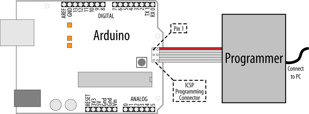
Connect an external in-system programmer (ISP) to the Arduino programming ICSP (In-Circuit Serial Programming) connector. Programmers intended for use with Arduino have a 6-pin cable that attaches to the 6-pin ICSP connector as shown in Figure 18-1.
Ensure that pin 1 from the programmer (usually marked with different color than the other wires) is connected to pin 1 on the ICSP connector. The programmer may have a switch or jumper to enable it to power the Arduino board; read the instructions for your programmer to ensure that the Arduino is powered correctly.
Select your programmer from the Tools menu. (AVRISP, AVRISPII, USBtinyISP, Parallel programmer, or Arduino as ISP) and double check that you have the correct Arduino board selected. From the File menu, select Upload Using Programmer to perform the upload.
Discussion
There are a number of different programmers available, from expensive devices aimed at professional developers that offer various debugging options, to low-cost self-build kits, or programming an additional Arduino to perform this function. The programmer may be a native USB device, or appear as a serial port. Check the documentation for your device to see what kind it is, and whether you need to install drivers for it.
Note
The serial Rx and Tx LEDs on the Arduino will not flicker during upload because the programmer is not using the hardware serial port.
Uploading using a programmer removes the bootloader code from the chip. This frees up the space the bootloader occupies and gives a little more room for your sketch code.
See Also
Code to convert an Arduino into an ISP programmer can be found in the sketch example named ArduinoISP. The comments in the sketch describe the connections to use.
See Recipe 18.13.
18.13. Replacing the Arduino Bootloader
Problem
You want to replace the bootloader. Perhaps you can’t get the board to upload programs and suspect the bootloader is not working. Or you want to replace an old bootloader with one with higher performance or different features.
Solution
Connect a programmer and select it as discussed in Recipe 18.12. Double check you have the correct board selected and click “Burn Bootloader” from the Tools menu.
A message will appear in the IDE saying “Burning bootloader to I/O board (this may take a minute)…” Programmers with status lights should indicate that the bootloader is being written to the board. You should see the LED connected to pin 13 flash as the board is programmed (pin 13 happens to be connected to one of the ICSP signal pins). If all goes well, you should get a message saying “Done Loading Bootloader.”
Disconnect the programmer and try uploading code through the IDE to verify it is working.
Discussion
The bootloader is a small program that runs on the chip and briefly checks each time the chip powers up to see if the IDE is trying upload code to the board. If so, the bootloader takes over and replaces the code on the chip with new code being uploaded through the serial port. If the bootloader does not detect a request to upload, it relinquishes control to the sketch code already on the board.
If you have used a serial programmer, you will need to switch the serial port back to the correct one for your Arduino board as described in Recipe 1.4.
See Also
Optiloader, maintained by Bill Westfield, is another way to update or install the bootloader. It uses an Arduino connected as an ISP programmer, but all the bootloaders are included in the Arduino sketch code. This means an Arduino with Optiloader can program another chip automatically when power is applied—no external computer needed. The code identifies the chip and loads the correct bootloader onto it.
18.14. Reprogram the Uno to Emulate a Native USB device
Problem
You want your Arduino Uno to appear like a native USB device instead of as a serial port, for example as a MIDI USB device to communicate directly with music programs on your computer.
Solution
Replace the code running on the Uno USB controller (ATmega8U2) chip so that it communicates with the computer as a native USB device rather than a serial port.
Warning
If the reprogramming is not done carefully, or a different
firmware is used that does not include the DFU firmware, you can get
the board into a state where you will need an external programmer to
fix it using a command-line utility named avrdude. If you are not familiar with
running command-line tools, you should think carefully before trying
out this recipe.
Start by programing the Uno board with the sketch that will be talking to the 8U2, as once you have reprogrammed the 8U2 it will be more difficult to change the sketch. Darran Hunt has written suitable code for this that you can download from: http://hunt.net.nz/users/darran/weblog/52882/attachments/1baa3/midi_usb_demo.pde (at the time of writing, this sketch used the old .pde extension but it is compatible with Arduino 1.0). Upload this to the Uno from the IDE in the usual way. This sketch will send commands to the 8U2 that will tell it what MIDI messages to send back to the computer.
Download the code to reprogram the 8U2 chip from http://hunt.net.nz/users/darran/weblog/52882/attachments/e780e/Arduino-usbmidi-0.2.hex.
You will also need programming software that can talk to the 8U2 chip:
- On Windows
Install the Atmel Flip program: http://www.atmel.com/dyn/products/tools_card.asp?tool_id=3886.
- Mac
Install the command line tool
dfu-programmer. A handy install script for installing is here: http://www.uriahbaalke.com/?p=106.- Linux
From terminal, type:
sudo apt-get install dfu-programmeorsudo aptitude install dfu-programmerdepending on your distribution.
Set the 8U2 into its reprogram mode: if your Uno has the 6-pin connector by the 8U2 chip populated with pins, then you just need to short the lefthand pair of pins (closest to the USB connector) together to put the chip in DFU mode.
Note
The first Uno boards (revision 1) did not have a resistor needed to reset the 8U2. If you are unable to reset your board, follow the instructions at http://arduino.cc/en/Hacking/DFUProgramming8U2. Halfway down the page it describes what to do if your board needs to have an external resistor added to enable resetting the 8U2 chip.
- On Windows
When the board is put into DFU mode for the first time, the Found New Hardware Wizard will appear. If the board installs without error then carry on. If the hardware installation fails (in the same way the Uno installation does) then you need to go into Device Manager and highlight the entry for Arduino DFU (it will have a yellow warning triangle next to it), right-click, and select update drivers. Navigate to the Flip 3.4.3 folder in Program Files/Atmel and select the USB folder. The drivers should now successfully install.
Launch the Flip program.
Select the device type AT90USB82 from the drop-down menu (it is the only active option when you first run the program). Click on the icon of a lead and select USB. If you get the error message
AtLibUsbDfu.dll not
              found
, the drivers have not installed. Follow the instructions above.Click on the Select EEPROM button at the bottom of the window and open
Arduino-usbmidi-0.2.hex. Select Run to the left of this button, and the program should go through the cycle listed above the button: Erase, Program, Verify. Unplug the board and plug it back in and it will show up as a MIDI device on your computer.- Mac and Linux
In terminal,
cdinto the folder with the hex file.Clear the chip by typing
sudo dfu-programmer at90usb82 erase.When this has finished, type
sudo dfu-ptogrammer at90usb82 flash Arduino-usbmidi-0.2.hex.Unplug the board and plug it back in to get the new firmware to run in the 8U2.
The operating system should now recognize the device as a MIDI device. Hook it up to a music program and you should hear a string of notes.
Discussion
Once the 8U2 is reprogrammed, the messages that are sent to the computer are still controlled by the sketch running on the main chip, but your computer sees the Arduino board as a MIDI device instead of a serial port. The sketch running on the main chip determines what gets sent to your computer, allowing Arduino to respond to switches and sensors to control what is played.
The IDE will not see the standard bootloader when the 8U2 has been reprogrammed as described in this Recipe, so to change the sketch you use an external programmer (see Recipe 18.12).
If you want to return your 8U2 to its original state, you can
obtain the required .HEX file at
https://github.com/arduino/Arduino/tree/master/hardware/arduino/firmwares.
Put this on the 8U2 using the procedure described above, but use this
hex file instead of the MIDI one.
If you have used other firmware that does not include the DFU loader (not all firmware found on the internet include it), or something has gone wrong and the board will not go into DFU mode, then you need to use an external programmer to replace the firmware.
This needs to be done from the command line using the upload utility named AVRdude (it cannot be done using the Arduino IDE).
Note
In order for the following command to work, you need to supply
the full path to avrdude, not
just the name. avrdude is located
inside your Arduino program folder: Arduino.app/Contents/Resources/Java/hardware/tools/avr/bin
on a Mac; hardware/tools/avr/bin inside the Arduino
folder on Windows. (Or you can add this location to your PATH
environment; Google “set path environment” for your operating system
for details.)
At the command line from the folder where the hex file is located, execute the following command:
- For the Uno
avrdude -p at90usb82 -F -P usb -c avrispmkii -U flash:w:UNO-dfu_and_usbserial_combined.hex -U lfuse:w:0xFF:m -U hfuse:w:0xD9:m -U efuse:w:0xF4:m -U lock:w:0x0F:m- For the Mega 2560
avrdude -p at90usb82 -F -P usb -c
              avrispmkii -U flash:w:MEGA-dfu_and_usbserial_combined.hex -U
              lfuse:w:0xFF:m -U hfuse:w:0xD9:m -U efuse:w:0xF4:m -U
              lock:w:0x0F:m
If your programming device is a serial device rather than USB
you will need to change -P usb to specify which serial port
(e.g., -P \.COM19 on Windows;
-P /dev/tty.usbserial- on Mac
(check the Arduino serial port menu for the name it appears as, and
what values XXXXXXXXXXXX are). Set the
-c avrispmkii based on the type of
programmer you have. For more details on this, see Recipe 18.12.
See Also
See Recipe 18.12.
Darran Hunt’s ATmega8U2 blog: http://hunt.net.nz/users/darran/
Updating the Atmega8U2 on an Uno or Mega2560 using DFU: http://arduino.cc/en/Hacking/DFUProgramming8U2
The Teensy and Teensy++ boards can emulate USB HID devices: http://www.pjrc.com/teensy/.
The Arduino Leonardo board supports emulation of USB HID devices. Leonardo had not been released when this book was printed; check the Arduino hardware page to see if it is available: http://www.arduinocc/en/Main/hardware.
See Recipe 9.6 for the conventional way to control MIDI from Arduino.
A tutorial covering the low-level avrdude programming tool: http://www.ladyada.net/make/usbtinyisp/avrdude.html