
Chapter 14. Wireless Communication
14.0. Introduction
Arduino’s ability to interact with the world is wonderful, but sometimes you might want to communicate with your Arduino from a distance, without wires, and without the overhead of a full TCP/IP network connection. This chapter covers various simple wireless modules for applications where low cost is the primary requirement but most of the recipes focus on the versatile XBee wireless modules.
XBee provides flexible wireless capability to the Arduino, but that very flexibility can be confusing. This chapter provides examples ranging from simple “wireless serial port replacements” through to mesh networks connecting multiple boards to multiple sensors.
A number of different XBee modules are available. The most popular are the XBee 802.15.4 (also known as XBee Series 1) and XBee ZB Series 2. Series 1 is easier to use than Series 2, but it does not support mesh networks. See http://www.digi.com/support/kbase/kbaseresultdetl.jsp?id=2213.
14.1. Sending Messages Using Low-Cost Wireless Modules
Problem
You want to transmit data between two Arduino boards using simple, low-cost wireless modules.
Solution
This recipe uses simple transmit and receive modules such as the SparkFun 315 MHz: WRL-10535 and WRL-10533, or the 434 MHz: WRL-10534 and WRL-10532.
Wire the transmitter as shown in Figure 14-1 and the receiver as in Figure 14-2. Some modules have the power line labeled VDD instead of Vcc.


The transmit sketch sends a simple text message to the receive sketch, which echoes the text to the Serial Monitor. The transmit and receive sketches use the VirtualWire library written by Mike McCauley to provide the interface to the wireless hardware. The library can be downloaded from http://www.open.com.au/mikem/arduino/VirtualWire-1.5.zip:
/*
  SimpleSend
  This sketch transmits a short text message using the VirtualWire library
  connect the Transmitter data pin to Arduino pin 12
*/

#include <VirtualWire.h>

void setup()
{
    // Initialize the IO and ISR
    vw_setup(2000);           // Bits per sec
}

void loop()
{
    send("hello");
    delay(1000);
}

void send (char *message)
{
  vw_send((uint8_t *)message, strlen(message));
  vw_wait_tx(); // Wait until the whole message is gone
}
The receive sketch also uses the VirtualWire library:
/*
  SimpleReceive
  This sketch  displays text strings received using VirtualWire
  Connect the Receiver data pin to Arduino pin 11
*/
#include <VirtualWire.h>

byte message[VW_MAX_MESSAGE_LEN];    // a buffer to hold the incoming messages
byte msgLength = VW_MAX_MESSAGE_LEN; // the size of the message


void setup()
{
    Serial.begin(9600);
    Serial.println("Ready");

    // Initialize the IO and ISR
    vw_setup(2000);             // Bits per sec
    vw_rx_start();              // Start the receiver
}

void loop()
{
    if (vw_get_message(message, &msgLength)) // Non-blocking
    {
        Serial.print("Got: ");
    for (int i = 0; i < msgLength; i++)
    {
        Serial.write(message[i]);
    }
    Serial.println();
    }
}
Discussion
The VirtualWire library defaults to pin 12 for transmit and pin
11 for receive, but see the documentation link at the end of this
recipe if you want to use different pins. Setup initializes the library. The loop code simply calls a send function that calls the library
vw_send and waits for the message
to be transmitted.
The receive side initializes the library receive logic and then
waits in loop for the message.
vw_get_message will return true if a message is available, and if so,
each character in the message is printed to the Serial Monitor.
The VirtualWire library handles the assembly of multiple bytes into packets, so sending binary data consists of passing the address of the data and the number of bytes to send.
The sending sketch that follows is similar to the transmit
sketch in this recipe’s Solution, but it fills the message buffer with
binary values from reading the analog input ports using analogRead. The size of the buffer is the
number of integers to be sent multiplied by the number of bytes in an
integer (the six analog integer values take 12 bytes because each
int is two bytes):
/*
  SendBinary
  Sends digital and analog pin values as binary data using VirtualWire library
  See SendBinary in Chapter 4
*/

#include <VirtualWire.h>

const int numberOfAnalogPins = 6; // how many analog pins to read

int data[numberOfAnalogPins];  // the data buffer

const int dataBytes = numberOfAnalogPins * sizeof(int); // the number of bytes
                                                        // in the data buffer

void setup()
{
    // Initialize the IO and ISR
    vw_setup(2000);           // Bits per sec
}

void loop()
{
  int values = 0;
  for(int i=0; i <= numberOfAnalogPins; i++)
  {
    // read the analog ports
    data[i] = analogRead(i); // store the values into the data buffer
  }
  send((byte*)data, dataBytes);
  delay(1000); //send every second
}


void send (byte *data, int nbrOfBytes)
{
  vw_send(data, nbrOfBytes);
  vw_wait_tx(); // Wait until the whole message is gone
}
Note
The sizeof operator is used
to determine the number of bytes in an int.
The receive side waits for messages, checks that they are the expected length, and converts the buffer back into the six integer values for display on the Serial Monitor:
/*
 SendBinary
 Sends digital and analog pin values as binary data using VirtualWire library
 See SendBinary in Chapter 4
 */

#include <VirtualWire.h>

const int numberOfAnalogPins = 6; // how many analog integer values to receive
int data[numberOfAnalogPins];  // the data buffer

// the number of bytes in the data buffer
const int dataBytes = numberOfAnalogPins * sizeof(int);

byte msgLength = dataBytes;


void setup()
{
  Serial.begin(9600);
  Serial.println("Ready");

  // Initialize the IO and ISR
  vw_set_ptt_inverted(true); // Required for DR3100
  vw_setup(2000);            // Bits per sec

  vw_rx_start();              // Start the receiver
}

void loop()
{
  if (vw_get_message((byte*)data, &msgLength)) // Non-blocking
  {
    Serial.println("Got: ");
    if(msgLength == dataBytes)
    {
      for (int i = 0; i <  numberOfAnalogPins; i++)
      {
        Serial.print("pin ");
        Serial.print(i);
        Serial.print("=");
        Serial.println(data[i]);
      }
    }
    else
    {
       Serial.print("unexpected msg length of ");
       Serial.println(msgLength);
    }
    Serial.println();
  }
}
The Serial Monitor will display the analog values on the sending Arduino:
Got:
pin 0=1023
pin 1=100
pin 2=227
pin 3=303
pin 4=331
pin 5=358
Bear in mind that the maximum buffer size for VirtualWire is 30
bytes long (the constant VW_MAX_MESSAGE_LEN
is defined in the library header file).
Wireless range can be up to 100 meters or so depending on supply voltage and antenna and is reduced if there are obstacles between the transmitter and the receiver.
Also note that the messages are not guaranteed to be delivered, and if you get out of range or there is excessive radio interference some messages could get lost. If you need a guaranteed wireless delivery mechanism, the ZigBee API used in recipes that follow is a better choice, but these inexpensive modules work well for tasks such as displaying the status of Arduino sensors—each message contains the current sensor value to display and any lost messages get replaced by messages that follow.
See Also
A technical document on the VirtualWire Library can be downloaded from http://www.open.com.au/mikem/arduino/VirtualWire.pdf.
Data sheets for the transmitter and receiver modules can be found at http://www.sparkfun.com/datasheets/Wireless/General/MO-SAWR.pdf and http://www.sparkfun.com/datasheets/Wireless/General/MO-RX3400.pdf.
14.2. Connecting Arduino to a ZigBee or 802.15.4 Network
Problem
You’d like your Arduino to participate in a ZigBee or 802.15.4 network.
802.15.4 is an IEEE standard for low-power digital radios that are implemented in products such as the inexpensive XBee modules from Digi International. ZigBee is an alliance of companies and also the name of a standard maintained by that alliance. ZigBee is based on IEEE 802.15.4 and is a superset of it. ZigBee is implemented in many products, including certain XBee modules from Digi.
Note
Only XBee modules that are listed as ZigBee-compatible, such as the XBee ZB modules, are guaranteed to be ZigBee-compliant. That being said, you can use a subset of the features (IEEE 802.15.4) of ZigBee even with the older XBee Series 1 modules. In fact, all the recipes here will work with the Series 1 modules.
Solution
Obtain two or more XBee modules, configure them (as described in Discussion) to communicate with one another, and hook them up to at least one Arduino. You can connect the other XBee modules to another Arduino, a computer, or an analog sensor (see Recipe 14.4).
If you connect the Arduino to the XBee and run this simple sketch, the Arduino will reply to any message it receives by simply echoing what the other XBee sends it:
/*
  XBeeEcho
 Reply with whatever you receive over the serial port
 */

void setup()
{
  Serial.begin(9600);
}

void loop()
{
  while (Serial.available() ) {
    Serial.write(Serial.read()); // reply with whatever you receive
  }
}
Figure 14-3 shows the connection between an Adafruit XBee Adapter and Arduino. Notice that the Arduino’s RX is connected to the XBee’s TX and vice versa.

Warning
If you are using a different adapter that does not have an on-board voltage regulator, it will be sending voltage directly into the XBee. If this is the case, you must connect the 3V3 pin from the Arduino to the adapter’s power supply, or you risk burning out your XBee.
With the XBees configured and connected to a computer and/or Arduino, you can send messages back and forth.
Warning
You must disconnect the Arduino from the XBee before you attempt to program the Arduino. This is because Arduino uses pins 0 and 1 for programming, and the signals will get crossed if anything else, such as an XBee, is connected to those pins.
Discussion
To configure your XBees, plug them in to an XBee adapter such as the Adafruit XBee Adapter kit ($10; Maker Shed part number MKAD13, Adafruit 126) and use a USB-to-TTL serial adapter such as the TTL-232R ($20; Maker Shed TTL232R, Adafruit 70) to connect the adapter to a computer.
Note
You should purchase at least two adapters (and if needed, two cables), which will allow you to have two XBees connected to your computer at the same time. These same adapters can be used to connect an XBee to an Arduino.
You could also use an all-in-one XBee USB adapter, such as the Parallax XBee USB Adapter ($20; Adafruit 247, Parallax 32400) or the SparkFun XBee Explorer USB ($25; SparkFun WRL-08687).
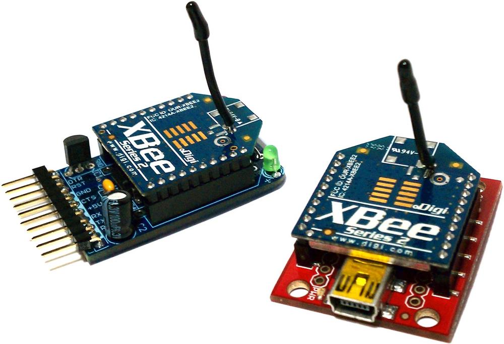
Figure 14-4 shows the Adafruit XBee Adapter and the SparkFun XBee Explorer USB with Series 2 XBee modules connected.
Series 2 configuration
For the initial configuration of Series 2 XBees, you will need to plug your XBees in to a Windows computer (the configuration utility is not available for Mac or Linux). Plug only one in to a USB port for now. The TTL-232R and Parallax XBee USB Adapter both use the same USB-to-serial driver as the Arduino itself, so you should not need to install an additional driver.
Open Device Manager (press Windows-R, type
devmgmt.msc, and press Enter), expand the Ports (COM & LPT) section, and take note of the number of the USB Serial Port the XBee you just plugged in is connected to (unplug it and plug it back in if it’s not obvious which port is correct). Exit Device Manager.Run the X-CTU application (http://www.digi.com/support/productdetl.jsp?pid=3352&osvid=0&tp=5&tp2=0), then select the serial port you identified in the previous step, and press Test/Query to ensure that X-CTU recognizes your XBee. (If not, see the support document at http://www.digi.com/support/kbase/kbaseresultdetl.jsp?id=2103.)
Switch to the Modem Configuration tab, and click Read. X-CTU will determine which model of XBee you are using as well as the current configuration.
Click the Version menu and pick the highest numbered version of the firmware available.
Click Show Defaults.
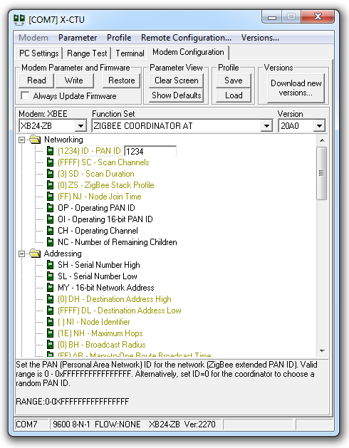
Change the PAN ID setting from 0 to 1234 (or any hexadecimal number you want, as long as you use the same PAN ID for all devices on the same network), as shown in Figure 14-5.
Click Write.
Click the Terminal tab.
Next, leave X-CTU running and leave that XBee plugged in. Plug your second XBee in to a different USB port. Repeat the preceding steps (in step 2, you will be starting up a second copy of X-CTU), but instead of choosing ZIGBEE COORDINATOR AT in step 4, choose ZIGBEE ROUTER AT. On this XBee, you should also set Channel Verification (JV) to 1 to make sure it will confirm that it’s on the right channel, which makes its connection to the coordinator more reliable.
Note
If you have two computers running Windows, you can connect each XBee into a separate computer.
With both XBees connected and two copies of X-CTU showing their Terminal tab, type into either Terminal window. You’ll see whatever you type into one XBee appear on the Terminal of the other one. You’ve set up your first simple XBee Personal Area Network (PAN). Now you can connect XBees to two Arduino boards and run the sketch as described in Talking to the Arduino.
Series 1 configuration
For Series 1 XBees, you can use a Mac or a PC running Linux or Windows. However, if you wish to update the firmware on the XBees, you will need to use the X-CTU utility described in Series 2 configuration.
Determine which serial port your XBee is using, as described in Finding Your Serial Port. Connect to this port in your serial terminal program. To connect to your XBee using CoolTerm (Windows or Mac), follow these steps:
Run CoolTerm.
Note
You can download CoolTerm for Windows and Mac at http://freeware.the-meiers.org/. PuTTY is available for Windows and Linux at http://www.chiark.greenend.org.uk/~sgtatham/putty/download.html. You may also be able to install PuTTY under Linux using your Linux system’s package manager. For example, on Ubuntu, PuTTY is available in the Universe repository with
apt-get install putty.Click the Options button in the toolbar.
Select the USB serial port (such as usbserial-A700eYw1 on a Mac or COM8 on a PC). Make sure it is set to a baud rate of 9,600, 8 data bits, no parity, 1 stop bit (these are the defaults).
Check the box labeled Local Echo.
Click OK.
Click the Save button in the toolbar and save your session settings.
In future sessions, you can skip steps 2 through 6 by clicking Open and selecting the settings file you saved.
Click the Connect button in the toolbar.
To connect to your XBee using PuTTY (Windows or Linux), follow these steps:
Run PuTTY.
Click Serial under Connection Type.
Type the name of your serial port in the Serial Line field (such as /dev/ttyUSB0 on Linux or COM7 on Windows). Make sure Speed is set to 9600 (the default).
On the left side of the window, under Category, click Terminal.
Under Local Echo, choose Force On.
Under “Set various terminal options,” choose Implicit LF in Every CR.
On the left side of the window, under Category, click Session.
Type a name for the session, such as “XBee 1,” then click Save.
In future sessions, you can skip steps 2 through 8 by double-clicking the saved session name. This will open the serial connection.
Now that you’re connected, configure the first XBee with the
following AT commands. You will need to type +++ and wait a second to get the XBee’s
attention (it will respond with “OK”):
ATMY1234
ATDL5678
ATDH0
ATID0
ATWR
Keep your Serial Terminal up and running so that you can continue to type commands into it. Next, plug in the second XBee, and follow the earlier instructions to connect to it with PuTTY or CoolTerm (to open a new PuTTY window, you can simply launch the program again; you can start a new CoolTerm window with File→New). Then, configure the second XBee with these commands:
ATMY5678
ATDL1234
ATDH0
ATID0
ATWR
Now you can type commands into the Serial Terminal window for one XBee and they will appear in the Serial Terminal window for the other XBee (and vice versa).
The ATMY command sets the identifier for an XBee. ATDL and ATDH set the low byte and the high byte of the destination
XBee. ATID sets the network ID (it needs to be the same for XBees
to talk to one another) and ATWR
saves the settings into the XBee so that it remembers
the settings even if you power it down and back up.
Talking to the Arduino
Now that you’ve got your XBee modules configured, pick one of
the XBees and close the Serial Terminal that was connected to it,
and disconnect it from your computer. Next, program your Arduino
with the code shown in this recipe’s Solution, and connect the XBee
to your Arduino as shown in Figure 14-3. When you type
characters into the Serial Terminal program connected to your other
XBee, you’ll see the characters echoed back (if you type a, you’ll see aa).
Note
If you see each character echoed back to you twice, it’s because you enabled local echo in the terminal program earlier in this recipe. You can disconnect and reconnect with Local Echo turned off (follow the earlier instructions for CoolTerm or PuTTY and make sure Local Echo is off) if you’d like.
14.3. Sending a Message to a Particular XBee
Solution
Send the AT commands directly from your Arduino sketch:
/*
  XBeeMessage
 Send a message to an XBee using its address
 */

boolean configured;

boolean configureRadio() {

  // put the radio in command mode:
  Serial.print("+++");

  String ok_response = "OK
"; // the response we expect.

  // Read the text of the response into the response variable
  String response = String("");
  while (response.length() < ok_response.length()) {
    if (Serial.available() > 0) {
      response += (char) Serial.read();
    }
  }

  // If we got the right response, configure the radio and return true.
  if (response.equals(ok_response)) {
    Serial.print("ATDH0013A200
"); // destination high-REPLACE THIS
    Serial.print("ATDL403B9E1E
"); // destination low-REPLACE THIS
    Serial.print("ATCN
");     // back to data mode
    return true;
  } else {
    return false; // This indicates the response was incorrect.
  }
}

void setup () {
  Serial.begin(9600); // Begin serial
  configured = configureRadio();
}

void loop () {
  if (configured) {
    Serial.print("Hello!");
    delay(3000);
  }
  else {
    delay(30000);     // Wait 30 seconds
    configured = configureRadio(); // try again
  }
}
Discussion
Although the configurations in Recipe 14.2 work for two XBees, they are not as flexible when used with more than two.
For example, consider a three-node network of Series 2 XBees, with one XBee configured with the COORDINATOR AT firmware and the other two with the ROUTER AT firmware. Messages you send from the coordinator will be broadcast to the two routers. Messages you send from each router are sent to the coordinator.
The Series 1 configuration in that recipe is a bit more flexible, in that it specifies explicit destinations: by configuring the devices with AT commands and then writing the configuration, you effectively hardcode the destination addresses in the firmware.
This solution instead lets the Arduino code send the AT commands
to configure the XBees on the fly. The heart of the solution is
the configureRadio()
function. It sends the +++ escape
sequence to put the XBee in command mode, just as the Series 1
configuration did at the end of Recipe 14.2. After sending this
escape sequence, the Arduino sketch waits for the OK response before
sending these AT commands:
ATDH0013A200ATDL403B9E1EATCN
Note
In your code, you must replace
0013A200 and
403B9E1E with the high and low addresses
of the destination radio.
The first two commands are similar to what is shown in the
Series 1 configuration at the end of Recipe 14.2, but the numbers
are longer. That’s because the example shown in that recipe’s Solution
uses Series 2–style addresses. As you saw in Recipe 14.2, you can specify
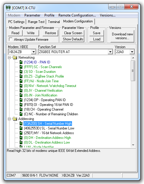
the address of a Series 1 XBee with the ATMY command, but in a Series 2 XBee, each module has a
unique address that is embedded in each chip. You can look up the
high (ATDH) and low
(ATDL) portions of the serial number using X-CTU, as shown in
Figure 14-6. The
numbers are also printed on the label underneath the XBee.
The ATCN command exits command mode; think of it as the reverse of what
the +++ sequence accomplishes.
See Also
14.4. Sending Sensor Data Between XBees
Problem
You want to send the status of digital and analog pins or control pins based on commands received from XBee.
Solution
Hook one of the XBees (the transmitting XBee) up to an analog sensor and configure it to read the sensor and transmit the value periodically. Connect the Arduino to an XBee (the receiving XBee) configured in API mode and read the value of the API frames that it receives from the other XBee.
Discussion
XBees have a built-in analog-to-digital converter (ADC) that can be polled on a regular basis. The XBee can be configured to transmit the values (between 0 and 1023) to other XBees in the network. The configuration and code differ quite a bit between Series 2 and Series 1 XBees.
Series 2 XBees
Using X-CTU (see Series 2 configuration in Recipe 14.2), configure the transmitting XBee with the ZIGBEE ROUTER AT (not API) function set and the following settings (click Write when you are done):
PAN ID: 1234 (or a
number you pick, as long as you use the same one for both
XBees) |
Channel Verification (JV): 1 (this makes sure the router will
confirm that it’s on the right channel when talking to the
coordinator) |
| Destination Address High (DH): the high address (SH) of the other XBee, usually 13A200 |
| Destination Address Low (DL): the low address (SL) of the other XBee |
Under I/O Settings, AD0/DIO0 Configuration (D0):
2 |
Under I/O Settings→Sampling Rate (IR): 64 (100 milliseconds in hex) |
Note
You can look up the high (ATDH) and low (ATDL) portions of the serial number
using X-CTU, as shown earlier in Figure 14-6. The numbers
are also printed on the label underneath the XBee.
Configure the receiving XBee with the ZIGBEE COORDINATOR API (not AT) function set with the following settings:
PAN ID: 1234 (or a
number you pick, as long as you use the same one for both
XBees) |
| Destination Address High (DH): the high address (SH) of the other XBee, usually 13A200 |
| Destination Address Low (DL): the low address (SL) of the other XBee |
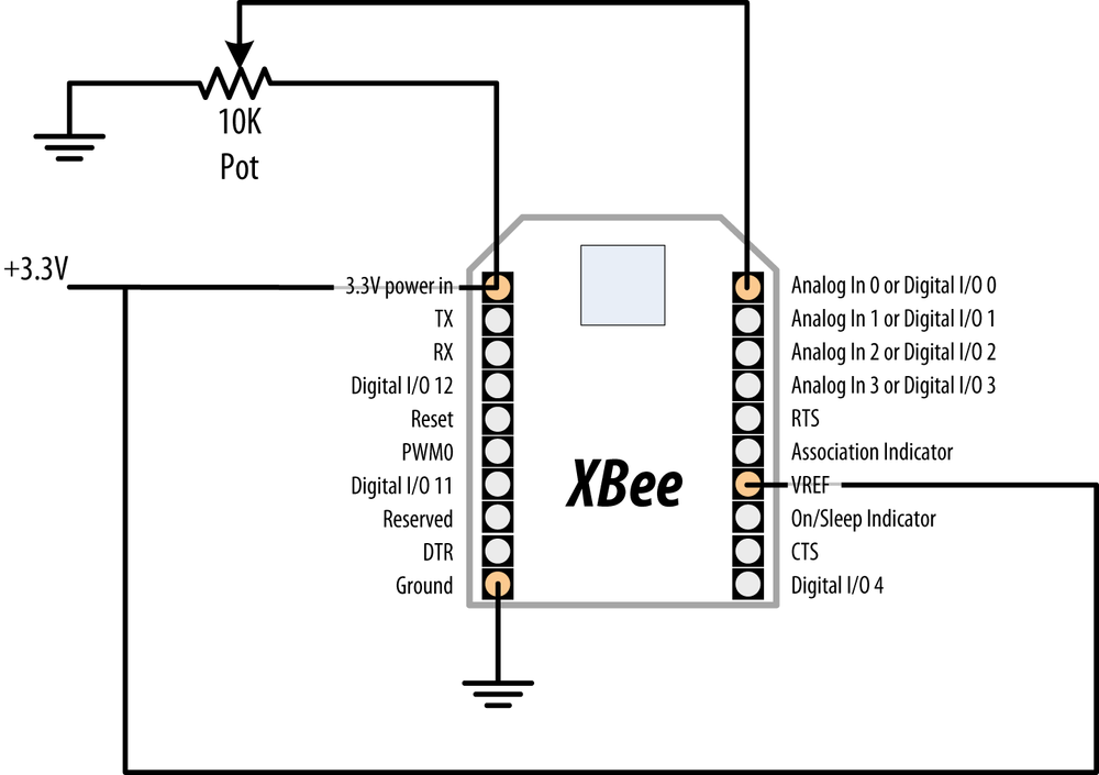
Wire up the transmitting XBee to the sensor, as shown in Figure 14-7. The value of R1 should be double whatever your potentiometer is (if you are using a 10K pot, use a 20K resistor). This is because the Series 2 XBees’ analog-to-digital converters read a range of 0 to 1.2 volts, and R1 reduces the 3.3 volts to stay below 1.2 volts.
Warning
Check the pinout of your XBee breakout board carefully, as the pins on the breakout board don’t always match up exactly to the pins on the XBee itself. For example, on some breakout boards, the upper left pin is GND, and the pin below it is 3.3V.

Next, load the following sketch onto the Arduino, and wire the transmitting XBee to the Arduino as shown in Recipe 14.2. If you need to reprogram the Arduino, remember to disconnect it from the XBee first:
/*
   XBeeAnalogReceive
  Read an analog value from an XBee API frame and set the brightness
  of an LED accordingly.
 */

#define LEDPIN 9

void setup() {
  Serial.begin(9600);
  pinMode(LEDPIN, OUTPUT);
}

void loop() {

  if (Serial.available() >= 21) { // Wait until we have a mouthful of data

     if (Serial.read() == 0x7E) { // Start delimiter of a frame

      // Skip over the bytes in the API frame we don't care about
      for (int i = 0; i < 18; i++) {
        Serial.read();
      }

      // The next two bytes are the high and low bytes of the sensor reading
      int analogHigh = Serial.read();
      int analogLow = Serial.read();
      int analogValue = analogLow + (analogHigh * 256);

      // Scale the brightness to the Arduino PWM range
      int brightness = map(analogValue, 0, 1023, 0, 255);

      // Light the LED
      analogWrite(LEDPIN, brightness);
    }
  }
}
Series 1 XBees
Using a terminal program as described in Series 1 configuration in Recipe 14.2, send the following configuration commands to the transmitting XBee:
ATRE
ATMY1234
ATDL5678
ATDH0
ATID0
ATD02
ATIR64
ATWR
Next, send the following configuration commands to the receiving XBee:
ATRE
ATMY5678
ATDL1234
ATDH0
ATID0
ATWR
- Both XBees
ATREresets the XBee to factory defaults. TheATMYcommand sets the identifier for an XBee.ATDLandATDHset the low byte and the high byte of the destination XBee.ATIDsets the network ID (it needs to be the same for XBees to talk to one another).ATWRsaves the settings into the XBee so that it remembers the settings even if you power it down and back up.- Transmitting XBee
ATD02configures pin 20 (analog or digital input 0) as an analog input;ATIR64tells the XBee to sample every 100 (64 hex) milliseconds and send the value to the XBee specified byATDLandATDH.
Wire up the transmitting XBee to the sensor, as shown in Figure 14-8.
Warning
Check the pinout of your XBee breakout board carefully, as the pins on the breakout board don’t always match up exactly to the pins on the XBee itself. For example, on some breakout boards, the upper left pin is GND, and the pin below it is 3.3V. Similarly, you might find that the VREF pin (labeled RES on the SparkFun XBee Explorer USB) is fifth from the bottom on the right, while it is fourth from the bottom on the XBee itself.
Note
Unlike Series 2, Series 1 XBee uses an external reference connected to 3.3V. Because the voltage on the slider of the pot can never be greater than the reference voltage, the resistor shown in Figure 14-7 is not needed.
Next, load the following sketch onto the Arduino, and wire the transmitting XBee to the Arduino as shown in Recipe 14.2. If you need to reprogram the Arduino, disconnect it from the XBee first:
/*
   XBeeAnalogReceiveSeries1
  Read an analog value from an XBee API frame and set the brightness
  of an LED accordingly.
 */

const int ledPin = 9;

void setup() {
  Serial.begin(9600);
  pinMode(ledPin, OUTPUT);
  configureRadio(); // check the return value if you need error handling
}

boolean configureRadio() {

  // put the radio in command mode:
  Serial.flush();
  Serial.print("+++");
  delay(100);

  String ok_response = "OK
"; // the response we expect.

  // Read the text of the response into the response variable
  String response = String("");
  while (response.length() < ok_response.length()) {
    if (Serial.available() > 0) {
      response += (char) Serial.read();
    }
  }

  // If we got the right response, configure the radio and return true.
  if (response.equals(ok_response)) {
    Serial.print("ATAP1
"); // Enter API mode
    delay(100);
    Serial.print("ATCN
");  // back to data mode
    return true;
  } else {
    return false; // This indicates the response was incorrect.
  }
}

void loop() {

  if (Serial.available() >= 14) { // Wait until we have a mouthful of data

     if (Serial.read() == 0x7E) { // Start delimiter of a frame

      // Skip over the bytes in the API frame we don't care about
      for (int i = 0; i < 10; i++) {
        Serial.read();
      }

      // The next two bytes are the high and low bytes of the sensor reading
      int analogHigh = Serial.read();
      int analogLow = Serial.read();
      int analogValue = analogLow + (analogHigh * 256);

      // Scale the brightness to the Arduino PWM range
      int brightness = map(analogValue, 0, 1023, 0, 255);

      // Light the LED
      analogWrite(ledPin, brightness);
    }
  }
}
Note
On the Series 1 XBees, the Arduino code needed to configure
the radio for API mode with an AT command (ATAP1). On Series 2 XBees, this is
accomplished by flashing the XBee with a different firmware
version. The reason for the return to data mode (ATCN) is because command mode was
entered earlier with +++ and a
return to data mode to receive data is required.
See Also
14.5. Activating an Actuator Connected to an XBee
Problem
You want to tell an XBee to activate a pin, which could be used to turn on an actuator connected to it, such as a relay or LED.
Solution
Configure the XBee connected to the actuator so that it will accept instructions from another XBee. Connect the other XBee to an Arduino to send the commands needed to activate the digital I/O pin that the actuator is connected to.
Discussion
The XBee digital/analog I/O pins can be configured for digital output. Additionally, XBees can be configured to accept instructions from other XBees to take those pins high or low. In Series 2 XBees, you’ll be using the Remote AT Command feature. In Series 1 XBees, you can use the direct I/O, which creates a virtual wire between XBees.
Series 2 XBees
Using X-CTU (see Series 2 configuration), configure the receiving XBee with the ZIGBEE ROUTER AT (not API) function set and the following settings:
PAN ID: 1234 (or a
number you pick, as long as you use the same one for both
XBees) |
Channel Verification (JV): 1 (this makes sure the router will
confirm that it’s on the right channel when talking to the
coordinator) |
| Destination Address High (DH): the high address (SH) of the other XBee, usually 13A200 |
| Destination Address Low (DL): the low address (SL) of the other XBee |
Under I/O Settings, AD1/DIO1 Configuration (D1):
4 (digital output,
low) |
Note
You can look up the high (ATDH) and low (ATDL) portions of the serial number
using X-CTU, as shown earlier in Figure 14-6. The numbers
are also printed on the label underneath the XBee.
Configure the transmitting XBee with the ZIGBEE COORDINATOR API (not AT) function set with the following settings:
PAN ID: 1234 (or a
number you pick, as long as you use the same one for both
XBees) |
| Destination Address High (DH): the high address (SH) of the other XBee, usually 13A200 |
| Destination Address Low (DL): the low address (SL) of the other XBee |
Wire up the receiving XBee to an LED, as shown in Figure 14-9.

Next, load the following sketch onto the Arduino, and wire the
transmitting XBee to the Arduino as shown in Recipe 14.2. If you need to
reprogram the Arduino, remember to disconnect it from the XBee
first. This sketch sends a Remote AT command (ATD14 or ATD15) that sets the state of pin 1
(ATD1) alternatingly on (digital
out high, 5) and off (digital out low, 4):
/*
  XBeeActuate
  Send a Remote AT command to activate a digital pin on another XBee.
 */

const byte frameStartByte = 0x7E;
const byte frameTypeRemoteAT  = 0x17;
const byte remoteATOptionApplyChanges = 0x02;

void setup() {
  Serial.begin(9600);
}

void loop()
{

  toggleRemotePin(1);
  delay(3000);
  toggleRemotePin(0);
  delay(2000);
}


byte sendByte(byte value) {
  Serial.write(value);
  return value;
}

void toggleRemotePin(int value) {  // 0 = off, nonzero = on

  byte pin_state;
  if (value) {
    pin_state = 0x5;
  } else {
    pin_state = 0x4;
  }

  sendByte(frameStartByte); // Begin the API frame

  // High and low parts of the frame length (not counting checksum)
  sendByte(0x0);
  sendByte(0x10);

  long sum = 0; // Accumulate the checksum

  sum += sendByte(frameTypeRemoteAT); // Indicate this frame contains a
                                      // Remote AT command

  sum += sendByte(0x0);  // frame ID set to zero for no reply

  // The following 8 bytes indicate the ID of the recipient.
  // Use 0xFFFF to broadcast to all nodes.
  sum += sendByte(0x0);
  sum += sendByte(0x0);
  sum += sendByte(0x0);
  sum += sendByte(0x0);
  sum += sendByte(0x0);
  sum += sendByte(0x0);
  sum += sendByte(0xFF);
  sum += sendByte(0xFF);

  // The following 2 bytes indicate the 16-bit address of the recipient.
  // Use 0xFFFE to broadcast to all nodes.
  sum += sendByte(0xFF);
  sum += sendByte(0xFF);

  sum += sendByte(remoteATOptionApplyChanges); // send Remote AT options

  // The text of the AT command
  sum += sendByte('D'),
  sum += sendByte('1'),

  // The value (0x4 for off, 0x5 for on)
  sum += sendByte(pin_state);

  // Send the checksum
  sendByte( 0xFF - ( sum & 0xFF));

  delay(10); // Pause to let the microcontroller settle down if needed
}
Series 1 XBees
Using a terminal program as described in Series 1 configuration, send the following configuration commands to the transmitting XBee (the one you’ll connect to the Arduino):
ATRE
ATMY1234
ATDL5678
ATDH0
ATID0
ATD13
ATICFF
ATWR
Next, send the following configuration commands to the receiving XBee:
ATRE
ATMY5678
ATDL1234
ATDH0
ATID0
ATD14
ATIU0
ATIA1234
ATWR
- Both XBees
ATREresets the XBee to factory defaults. TheATMYcommand sets the identifier for an XBee.ATDLandATDHset the low byte and the high byte of the destination XBee.ATIDsets the network ID (it needs to be the same for XBees to talk to one another).ATWRsaves the settings into the XBee so that it remembers the settings even if you power it down and back up.- Transmitting XBee
ATICFFtells the XBee to check every digital input pin and send their values to the XBee specified byATDLandATDH.ATD13configures pin 19 (analog or digital input 1) to be in digital input mode. The state of this pin will be relayed from the transmitting XBee to the receiving XBee.- Receiving XBee
ATIU1tells the XBee to not send the frames it receives to the serial port.ATIA1234tells it to accept commands from the other XBee (whose MY address is 1234).ATD14configures pin 19 (analog or digital input 1) to be in low digital output mode (off by default).
Wire up the transmitting XBee to the Arduino, as shown in Figure 14-10.
Next, wire the receiving XBee to an Arduino, as shown in Recipe 14.2. Note that instead of sending AT commands over the serial port, we’re using an electrical connection to take the XBee’s pin high. The two 10K resistors form a voltage divider that drops the Arduino’s 5V logic to about 2.5 volts (high enough for the XBee to recognize, but low enough to avoid damaging the XBee’s 3.3V logic pins).

Next, load the following sketch onto the transmitting Arduino. This sketch takes the XBee’s digital I/O pin 1 alternatingly on (digital out high, 5) and off (digital out low, 4). Because the transmitting XBee is configured to relay its pin states to the receiving XBee, when its pin 1 changes state the receiving XBee’s pin 1 changes as well:
/*
  XBeeActuateSeries1
  Activate a digital pin on another XBee.
 */

const int xbeePin = 2;

void setup() {
  pinMode(xbeePin, OUTPUT);
}

void loop()
{

  digitalWrite(xbeePin, HIGH);
  delay(3000);
  digitalWrite(xbeePin, LOW);
  delay(3000);
}
See Also
14.6. Sending Messages Using Low-Cost Transceivers
Problem
You want a low-cost wireless solution with more capability than the simple modules in Recipe 14.1.
Solution
Use the increasingly popular Hope RFM12B modules to send and receive data. This Recipe uses two Arduino boards and wireless modules. One pair reads and sends values and the other displays the received value—both pairs are wired the same way.
Connect the modules as shown in Figure 14-11. The Antenna is just a piece of wire cut to the correct length for the frequency of your modules; use 78 mm for 915 MHz, 82 mm for 868 MHz and 165 mm for 433 MHz.

If you are using a 3.3 volt Arduino such as the Fio or 3.3V Arduino Pro, eliminate the resistors and wire Arduino pins 10, 11, and 13 directly to the respective RFM12B pins.
The transmit sketch sends values from the six analog pins every second:
/*
 * SimpleSend
 * RFM12B wireless demo - transmitter - no ack
 * Sends values of analog inputs 0 through 6
 *
 */

#include <RF12.h>  //from jeelabs.org
#include <Ports.h>

// RF12B constants:
const byte network  = 100;   // network group (can be in the range 1-255).
const byte myNodeID = 1;     // unique node ID of receiver (1 through 30)

//Frequency of RF12B can be RF12_433MHZ, RF12_868MHZ or RF12_915MHZ.
const byte freq = RF12_868MHZ; // Match freq to module

const byte RF12_NORMAL_SENDWAIT = 0;

void setup()
{
  rf12_initialize(myNodeID, freq, network);   // Initialize RFM12
}

const int payloadCount = 6; // the number of integers in the payload message
int payload[payloadCount];

void loop()
{
  for( int i= 0; i < payloadCount; i++)
  {
    payload[i] = analogRead(i);
  }
  while (!rf12_canSend())  // is the driver ready to send?
    rf12_recvDone();       // no, so service the driver

  rf12_sendStart(rf12_hdr, payload, payloadCount*sizeof(int));
  rf12_sendWait(RF12_NORMAL_SENDWAIT); // wait for send completion

  delay(1000);  // send every second
}
The receive sketch displays the six analog values on the Serial Monitor:
/*
 * SimpleReceive
 * RFM12B wireless demo - receiver - no ack
 *
 */

#include <RF12.h>    //from jeelabs.org
#include <Ports.h>

// RFM12B constants:
const byte network  = 100;   // network group (can be in the range 1-255).
const byte myNodeID = 2;     // unique node ID of receiver (1 through 30)

// Frequency of RFM12B can be RF12_433MHZ, RF12_868MHZ or RF12_915MHZ.
const byte freq = RF12_868MHZ; // Match freq to module

void setup()
{
  rf12_initialize(myNodeID,freq,network);   // Initialize RFM12 with settings above
  Serial.begin(9600);
  Serial.println("RFM12B Receiver ready");
  Serial.println(network,DEC);   // print the network
  Serial.println(myNodeID,DEC);  // and node ID
}

const int payloadCount = 6; // the number of integers in the payload message

void loop()
{
  if (rf12_recvDone() && rf12_crc == 0 && (rf12_hdr & RF12_HDR_CTL) == 0)
  {
    int *payload = (int*)rf12_data;  // access rf12 data buffer as an arrya of ints
    for( int i= 0; i < payloadCount; i++)
    {
      Serial.print(payload[i]);
      Serial.print(" ");
    }
    Serial.println();
  }
}
Discussion
The RFM12B modules are designed for 3.3 volts and the resistors shown in Figure 14-11 are needed to drop the voltage to the correct level. The JeeLabs website http://jeelabs.com/products/rfm12b-board has details on breakout boards and modules for the RFM12B.
The RF12 library provides for different groups of modules to be used in the same vicinity where each group is identified by a network ID. Your send and receive sketches must use the same network ID to communicate with each other. Each node must have a unique ID within a network. In this example, the network is set for 100 with the sender using ID 1 and the receiver using ID 2.
The loop code fills an array (see Recipe 2.4) named payload with the six integer values read
from analog input ports 0 through 5.
The sending is achieved by calling rf12_sendStart; the rf12-hdr argument determines the target
node, which by default will be 0 (sending to node 0 will broadcast to
all nodes on the network); &payload is the address of the payload
buffer; payloadCount * sizeof(int) is the number of bytes in the
buffer. rf12_sendWait waits for
completion of the send (see the RF12 documentation for information
about power down options).
This code does not check to see if messages are acknowledged. In applications like this, that repeatedly send information, this is not a problem because the occasional lost message will be updated with the next send. See the example code in the library download for sketches that show other techniques for sending and receiving data.
Any kind of data that fits within a 66-byte buffer can be sent. For example, the following sketch sends a binary data structure consisting of an integer and floating point value:
/*
 * RFM12B wireless demo - struct sender - no ack
 * Sends a floating point value using a C structure
 */

#include <RF12.h> //from jeelabs.org
#include <Ports.h>

// RF12B constants:
const byte network  = 100;   // network group (can be in the range 1-255)
const byte myNodeID = 1;     // unique node ID of receiver (1 through 30)

// Frequency of RF12B can be RF12_433MHZ, RF12_868MHZ or RF12_915MHZ.
const byte freq = RF12_868MHZ; // Match freq to module

const byte RF12_NORMAL_SENDWAIT = 0;

void setup()
{
  rf12_initialize(myNodeID, freq, network);   // Initialize RFM12
}

typedef struct {  // Message data Structure, this must match Tx
  int pin;  // pin number used for this measurement
  float value;  // floating point measurement value
}
Payload;

Payload sample;  // declare an instance of type Payload named sample

void loop()
{
  int inputPin = 0; // the input pin
  float value = analogRead(inputPin) * 0.01; // a floating point value
  sample.pin = inputPin; // send demontx.ct1=emontx.ct1+1;
  sample.value = value;

  while (!rf12_canSend())  // is the driver ready to send?
    rf12_recvDone();       // no, so service the driver

  rf12_sendStart(rf12_hdr, &sample, sizeof sample);
  rf12_sendWait(RF12_NORMAL_SENDWAIT);  // wait for send completion

  Serial.print(sample.pin);
  Serial.print(" = ");
  Serial.println(sample.value);
  delay(1000);
}
Here is the sketch that receives and displays the struct
data:
/*
 * RFM12B wireless demo - struct receiver - no ack
 *
 */


#include <RF12.h>  // from jeelabs.org
#include <Ports.h>

// RF12B constants:
const byte network  = 100;   // network group (can be in the range 1-255)
const byte myNodeID = 2;     // unique node ID of receiver (1 through 30)

// Frequency of RF12B can be RF12_433MHZ, RF12_868MHZ or RF12_915MHZ.
const byte freq = RF12_868MHZ; // Match freq to module

void setup()
{
  rf12_initialize(myNodeID,freq,network);   // Initialize RFM12 with settings above
  Serial.begin(9600);
  Serial.print("RFM12B Receiver ready");
}

typedef struct {  // Message data Structure, this must match Tx
  int   pin;	  // pin number used for this measurement
  float value;	  // floating point measurement value
}
Payload;

Payload sample;         // declare an instance of type Payload named sample

void loop() {

  if (rf12_recvDone() && rf12_crc == 0 && (rf12_hdr & RF12_HDR_CTL) == 0)
  {
    sample = *(Payload*)rf12_data;            // Access the payload
    Serial.print("AnalogInput ");
    Serial.print(sample.pin);
    Serial.print(" = ");
    Serial.println(sample.value);
  }
}
This code is similar to the previous pair of sketches with the
payload buffer replaced by a
pointer named sample that points to
the Payload structure.
See Also
The libraries used in this recipe were developed by Jean-Claude Wippler. A wealth of information is available on his site: http://www.jeelabs.com.
Each function of the RF12 library is documented here: http://jeelabs.net/projects/cafe/wiki/RF12.
An example sketch for sending strings with the RFM12 can be found here: http://jeelabs.org/2010/09/29/sending-strings-in-packets.
An example using sleep mode to save power between sends can be found here: https://github.com/openenergymonitor/emonTxFirmware.
A breakout board for the RFM12B is available here: http://jeelabs.com/products/rfm12b-board.
JeeNode is a board that combines the RFM12B and an Arduino-compatible chip: http://http://jeelabs.com/products/jeenode.
RFM12B 915 MHz versions of the module for use in the USA are available from Modern Device: http://shop.moderndevice.com/collections/jeelabs.
A 433 MHz version of RFM12B that should work anywhere in the world is available from SparkFun: http://www.sparkfun.com/products/9582.
14.7. Communicating with Bluetooth Devices
Problem
You want to send and receive information to another device using Bluetooth; for example, a laptop or cellphone.
Solution
Connect Arduino to a Bluetooth module such as the BlueSMiRF, Bluetooth Mate, or Bluetooth Bee, as shown in Figure 14-12.

This sketch is similar to the one in Recipe 4.13; it monitors characters received on the hardware serial port and a software serial port (connected to Bluetooth), so anything received on one is sent to the other:
/*
 * Use SoftwareSerial to talk to BlueSMiRF module
 * note pairing code is 1234
 */

#include <SoftwareSerial.h>

const int rxpin = 2;           // pin used to receive
const int txpin = 3;           // pin used to send to
SoftwareSerial bluetooth(rxpin, txpin); // new serial port on given pins

void setup()
{
  Serial.begin(9600);
  bluetooth.begin(9600); // initialize the software serial port
  Serial.println("Serial ready");
  bluetooth.println("Bluetooth ready");
}

void loop()
{
  if (bluetooth.available())
  {
    char c = (char)bluetooth.read();
    Serial.write(c);
  }
  if (Serial.available())
  {
    char c = (char)Serial.read();
    bluetooth.write(c);
  }
}
Discussion
You will need Bluetooth capability on your computer (or phone) to communicate with this sketch. Both sides participating in a Bluetooth conversation need to be paired—the ID of the module connected to Arduino needs to be known to the other end. The default ID for the BlueSMiRF is 1234. See the documentation for your computer/phone Bluetooth to set the pairing ID and accept the connection.
If you have a board that plugs in to an FTDI cable, you can directly plug in a Bluetooth Mate module. (See Figure 14-13.)

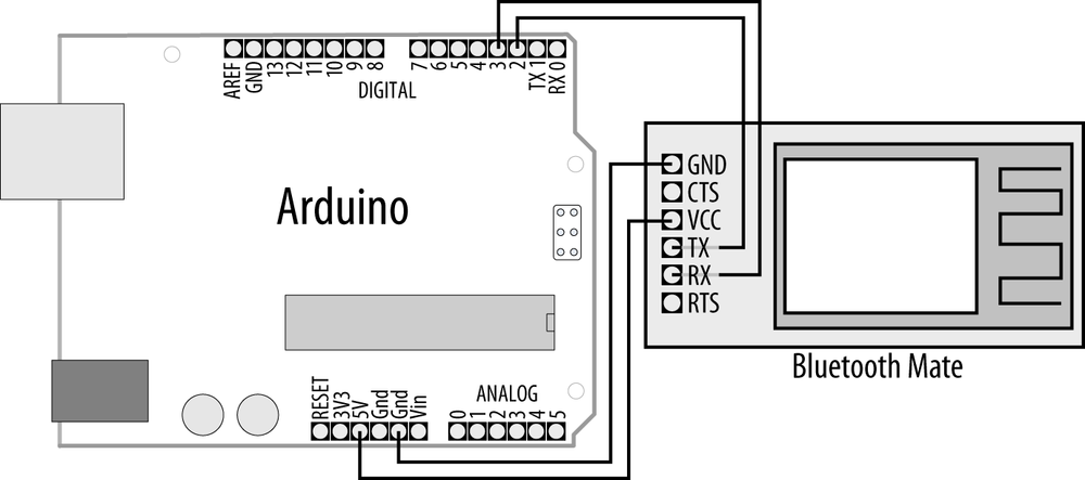
The Bluetooth Mate can also be wired to use with a standard board, as shown in Figure 14-14.
Note
All the common Bluetooth modules used with Arduino implement the Bluetooth Serial Port Profile (SPP). Once the devices are paired, the computer or phone will see the module as a serial port. These modules are not capable of appearing as other types of Bluetooth service, such as a Bluetooth mouse or keyboard.
Bluetooth range is between 5 and 100 meters, depending on whether you have class 3, 2, or 1 devices.
See Also
A SparkFun tutorial covering the installation and use of Bluetooth: http://www.sparkfun.com/tutorials/67
Bluetooth Bee is a Bluetooth module that plugs in to an XBee socket so you can use shields and adapters designed for XBee: http://www.seeedstudio.com/depot/bluetooth-bee-p-598.html.