
Chapter 5. Simple Digital and Analog Input
5.0. Introduction
The Arduino’s ability to sense digital and analog inputs allows it to respond to you and to the world around you. This chapter introduces techniques you can use to do useful things with these inputs. This is the first of many chapters to come that cover electrical connections to Arduino. If you don’t have an electronics background, you may want to look through Appendix A on electronic components, Appendix B on schematic diagrams and data sheets, Appendix C on building and connecting circuits, and Appendix E on hardware troubleshooting. In addition, many good introductory tutorials are available. Two that are particularly relevant to Arduino are Getting Started with Arduino by Massimo Banzi and Making Things Talk by Tom Igoe (both O’Reilly; search on oreilly.com). Other books offering a background on electronics topics covered in this and the following chapters include Getting Started in Electronics by Forrest Mims (Master Publishing) and Physical Computing by Tom Igoe (Cengage).
Warning
If wiring components to your Arduino is new to you, be careful about how you connect and power the things you attach. Arduino uses a robust controller chip that can take a fair amount of abuse, but you can damage the chip if you connect the wrong voltages or short-circuit an output pin. Most Arduino controller chips are powered by 5 volts, and you must not connect external power to Arduino pins with a higher voltage than this (or 3.3 volts if your Arduino controller runs on this voltage).
Most Arduino boards have the main chip in a socket that can be removed and replaced, so you don’t need to replace the whole board if you damage the chip.
Figure 5-1 shows the arrangement of pins on a standard Arduino board. See http://www.arduino.cc/en/Main/Hardware for a list of all the official boards along with links to connection information for each. If your board is not on that list, check your board supplier’s website for connection information.

This chapter covers the Arduino pins that can sense digital and analog inputs. Digital input pins sense the presence and absence of voltage on a pin. Analog input pins measure a range of voltages on a pin.
The Arduino function to detect digital input is digitalRead and it
tells your sketch if a voltage on a pin is HIGH (5 volts) or LOW (0 volts). The Arduino function to
configure a pin for reading input is pinMode(pin, INPUT).
On a typical board, there are 14 digital pins (numbered 0 to 13) as shown at the top of Figure 5-1. Pins 0 and 1 (marked RX and TX) are used for the USB serial connection and should be avoided for other uses. If you need more digital pins on a standard board, you can use the analog pins as digital pins (analog pins 0 through 5 can be used as digital pins 14 through 19).
Arduino 1.0 introduced logical names for many of the pins. The constants in Table 5-1 can be used in all functions that expect a pin number.
Constant | Pin Number | Constant | Pin Number |
| Analog input 0 (Digital 14) | LED_BUILTIN | On-board LED (Digital 13) |
| Analog input 1 (Digital 15) | SDA | I2C Data (Digital 18) |
| Analog input (Digital 16) | SCL | I2C Clock (Digital 19) |
| Analog input (Digital 17) | SS | SPI Select (Digital 10) |
| Analog input (Digital 18) | MOSI | SPI Input (Digital 11) |
| Analog input (Digital 19) | MISO | SPI Output (Digital 12) |
| SCL | SPI Clock (Digital 13) |
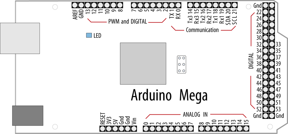
The Mega board has many more digital and analog pins. Digital pins 0 through 13 and analog pins 0 through 5 are located in the same place as on the standard board, so that hardware shields designed for the standard board can fit onto a Mega. As with the standard board, you can use analog pins as digital pins, but with the Mega, analog pins 0 through 15 are digital pin numbers 54 through 69. Figure 5-2 shows the Mega pin layout.
Most boards have an LED connected to pin 13, and some of the recipes use this as an output indicator. If your board does not have an LED on pin 13, skip ahead to Recipe 7.1 if you need help connecting an LED to a digital pin.
Recipes covering digital input sometimes use external resistors to
provide the voltage that is sensed by digitalRead. These
resistors are called pull-up resistors (so named because
the voltage is “pulled up” to the 5V line that the resistor is connected
to) or pull-down resistors (the voltage is
“pulled down” to 0 volts). Although 10K ohms is a commonly used value,
anything between 4.7K and 20K or more will work; see Appendix A for more information about the
components used in this chapter.
Unlike a digital value, which is only on or off, analog values are
continuously variable. The volume setting of a device is a good example;
it is not just on or off, but it can have a range of values in between.
Many sensors provide information by varying the voltage to correspond to
the sensor measurement. Arduino code uses a function called analogRead to get a value proportional to the
voltage it sees on one of its analog pins. The value will be 0 if there
are 0 volts on the pin and 1,023 for 5 volts. The value in between will
be proportional to the voltage on the pin, so 2.5 volts (half of 5
volts) will result in a value of roughly 511 (half of 1,023). You can
see the six analog input pins (marked 0 to 5) at the bottom of Figure 5-1 (these pins can also be used as
digital pins 14 to 19 if they are not needed for analog). Some of the
analog recipes use a potentiometer
(pot for short, also called a variable resistor) to vary the
voltage on a pin. When choosing a potentiometer, a value of 10K is the
best option for connecting to analog pins.
Although most of the circuits in this chapter are relatively easy to connect, you may want to consider getting a solderless breadboard to simplify your wiring to external components: some choices are the Jameco 20723 (two bus rows per side); RadioShack 276-174 (one bus row per side); Digi-Key 438-1045-ND; and SparkFun PRT-00137.
Another handy item is an inexpensive multimeter. Almost any will do, as long as it can measure voltage and resistance. Continuity checking and current measurement are nice additional features to have. (The Jameco 220812, RadioShack 22-810, and SparkFun TOL-00078 offer these features.)
5.1. Using a Switch
Problem
You want your sketch to respond to the closing of an electrical contact; for example, a pushbutton or other switch or an external device that makes an electrical connection.
Solution
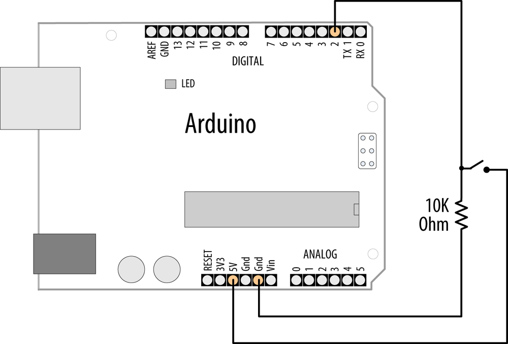
Use digitalRead to determine the state of a switch connected to an
Arduino digital pin set as input. The following code lights an
LED when a switch is pressed (Figure 5-3 shows how it
should be wired up):
/*
   Pushbutton sketch
   a switch connected to pin 2 lights the LED on pin 13
*/

const int ledPin = 13;            // choose the pin for the LED
const int inputPin = 2;           // choose the input pin (for a pushbutton)

void setup() {
  pinMode(ledPin, OUTPUT);         // declare LED as output
  pinMode(inputPin, INPUT);        // declare pushbutton as input
}

void loop(){
  int val = digitalRead(inputPin);  // read input value
  if (val == HIGH)                  // check if the input is HIGH
  {
    digitalWrite(ledPin, HIGH);     // turn LED on if switch is pressed
  }
  else
  {
    digitalWrite(ledPin, LOW);      // turn LED off
  }
}
Note
Standard Arduino boards have a built-in LED connected to pin 13. If your board does not, see Recipe 7.1 for information on connecting an LED to an Arduino pin.
Discussion
The setup function configures
the LED pin as OUTPUT and the
switch pin as INPUT.
Note
A pin must be set to OUTPUT
mode for digitalWrite to control
the pin’s output voltage. It must be in INPUT mode to read the digital
input.
The digitalRead function monitors the voltage on the input pin (inputPin), and it returns a value of
HIGH if the voltage is high (5
volts) and LOW if the voltage is
low (0 volts). Actually, any voltage that is greater than 2.5 volts
(half of the voltage powering the chip) is considered HIGH and less than this is treated as
LOW. If the pin is left unconnected
(known as floating), the value returned from
digitalRead is indeterminate (it
may be HIGH or LOW, and it cannot be reliably used). The
resistor shown in Figure 5-3 ensures that the
voltage on the pin will be low when the switch is not pressed, because
the resistor “pulls down” the voltage to ground. When the switch is
pushed, a connection is made between the pin and +5 volts, so the
value on the pin interpreted by digitalRead changes from LOW to HIGH.
Warning
Do not connect a digital or analog pin to a voltage higher than 5 volts (or 3.3 volts on a 3.3V board). This can damage the pin and possibly destroy the entire chip. Also, make sure you don’t wire the switch so that it shorts the 5 volts to ground (without a resistor). Although this may not damage the Arduino chip, it is not good for the power supply.
In this example, the value from digitalRead is stored in the variable
val. This will be HIGH if the button is pressed, LOW otherwise.
Note
The switch used in this example (and almost everywhere else in this book) makes electrical contact when pressed and breaks contact when not pressed. These switches are called Normally Open (NO); see this book’s website for part numbers. The other kind of momentary switch is called Normally Closed (NC).
The output pin connected to the LED is turned on when you set
val to HIGH, illuminating the LED.
Although Arduino sets all digital pins as inputs by default, it is a good practice to set this explicitly in your sketch to remind yourself about the pins you are using.
You may see similar code that uses true instead of HIGH; these can be used interchangeably
(they are also sometimes represented as 1). Likewise, false is the same as LOW and 0. Use the form that best expresses the
meaning of the logic in your application.
Almost any switch can be used, although the ones called momentary tactile switches are popular because they are inexpensive and can plug directly into a breadboard. See the website for this book for some supplier part numbers.
Here is another way to implement the logic in the preceding sketch:
void loop()
{
    digitalWrite(ledPin, digitalRead(inputPin));  // turn LED ON if input pin is
                                                  // HIGH, else turn OFF
}
This doesn’t store the button state into a variable. Instead, it
sets the LED on or off directly from the value obtained from digitalRead. It is a handy shortcut, but if
you find it overly terse, there is no practical difference in
performance, so pick whichever form you find easier to
understand.
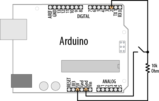
The pull-up code is similar to the pull-down version, but the logic is
reversed: the value on the pin goes LOW when the button is pressed (see Figure 5-4 for a schematic
diagram of this). It may help to think of this as pressing the switch
DOWN, causing the output to go
LOW:
void loop()
{
  int val = digitalRead(inputPin);  // read input value
  if (val == HIGH)                  // check if the input is HIGH
  {
    digitalWrite(ledPin, LOW);      // turn LED OFF
  }
  else
  {
    digitalWrite(ledPin, HIGH);     // turn LED ON
  }
}
See Also
The Arduino reference for digitalRead: http://arduino.cc/en/Reference/DigitalRead
The Arduino reference for digitalWrite:
http://arduino.cc/en/Reference/DigitalWrite
The Arduino reference for pinMode: http://arduino.cc/en/Reference/PinMode
The Arduino references for constants (HIGH, LOW, etc.): http://arduino.cc/en/Reference/Constants
Arduino tutorial on digital pins: http://arduino.cc/en/Tutorial/DigitalPins
5.2. Using a Switch Without External Resistors
Problem
You want to simplify your wiring by eliminating external pull-up resistors when connecting switches.
Solution
As explained in Recipe 5.1, digital
inputs must have a resistor to hold the pin to a known value when the
switch is not pressed. Arduino has internal pull-up resistors that can
be enabled by writing a HIGH value
to a pin that is in INPUT mode (the
code for this is shown in Recipe 5.1).
For this example, the switch is wired as shown in Figure 5-5. This is almost exactly the same as Figure 5-4, but without an external resistor.

The switch is only connected between pin 2 and Gnd. Gnd is short for ground and is at 0 volts by definition:
/*
  Pullup sketch
  a switch connected to pin 2 lights the LED on pin 13
*/

const int ledPin = 13;          // output pin for the LED
const int inputPin = 2;         // input pin for the switch

void setup() {
  pinMode(ledPin, OUTPUT);
  pinMode(inputPin, INPUT);
  digitalWrite(inputPin,HIGH);  // turn on internal pull-up on the inputPin
}void loop(){
  int val = digitalRead(inputPin);  // read input value
  if (val == HIGH)                  // check if the input is HIGH
  {
    digitalWrite(ledPin, HIGH);     // turn LED ON
  }
  else
  {
    digitalWrite(ledPin, LOW);      // turn LED OFF
  }
}
Note
There is more than one Gnd pin on an Arduino board; they are all connected together, so pick whichever is convenient.
Discussion
You enable internal pull-up resistors by writing a HIGH value to a pin in input mode.
Using digitalWrite(pin, HIGH) on a pin in input mode may not be
intuitive at first, but you’ll soon get used to it. You can turn the
pull-up off by writing a LOW value
to the pin.
If your application switches the pin mode back and forth between
input and output, bear in mind that the state of the pin will remain
HIGH or LOW when you change modes. In other words,
if you have set an output pin HIGH
and then change to input mode, the pull-up will be on, and reading the
pin will produce a HIGH. If you set
the pin LOW in output mode with
digitalWrite(pin, LOW) and then change to input mode
with pinMode(pin, INPUT), the pull-up will be off. If you
turn a pull-up on, changing to output mode will set the pin HIGH, which could, for example,
unintentionally light an LED connected to it.
The internal pull-up resistors are 20K ohms or more (between 20K and 50K). This is suitable for most applications, but some devices may require lower-value resistors—see the data sheet for external devices you want to connect to Arduino to see if the internal pull-ups are suitable or not.
5.3. Reliably Detecting the Closing of a Switch
Problem
You want to avoid false readings due to contact bounce (contact bounce produces spurious signals at the moment the switch contacts close or open). The process of eliminating spurious readings is called debouncing.
Solution
There are many ways to solve this problem; here is one using the wiring shown in Figure 5-3 from Recipe 5.1:
/*
 * Debounce sketch
 * a switch connected to pin 2 lights the LED on pin 13
 * debounce logic prevents misreading of the switch state
 */

const int inputPin = 2;        // the number of the input pin
const int ledPin = 13;         // the number of the output pin
const int debounceDelay = 10;  // milliseconds to wait until stable

// debounce returns the state when the switch is stable
boolean debounce(int pin)
{
  boolean state;
  boolean previousState;

  previousState = digitalRead(pin);          // store switch state
  for(int counter=0; counter < debounceDelay; counter++)
  {
      delay(1);                  // wait for 1 millisecond
      state = digitalRead(pin);  // read the pin
      if( state != previousState)
      {
         counter = 0; // reset the counter if the state changes
         previousState = state;  // and save the current state
      }
  }
  // here when the switch state has been stable longer than the debounce period
  return state;
}

void setup()
{
  pinMode(inputPin, INPUT);
  pinMode(ledPin, OUTPUT);
}

void loop()
{
  if (debounce(inputPin))
  {
    digitalWrite(ledPin, HIGH);
  }
}
The debounce function
is called (used) with the pin number of the switch you
want to debounce; the function returns true if the switch is pressed and stable. It
returns false if it is not pressed
or not yet stable.
Discussion
The debounce method checks to
see if it gets the same reading from the switch after a delay that
needs to be long enough for the switch contacts to stop bouncing. You
may require longer intervals for “bouncier” switches (some switches
can require as much as 50 ms or more). The function works by
repeatedly checking the state of the switch for as many milliseconds
as defined in the debounce time. If
the switch remains stable for this time, the state of the switch will
be returned (true if pressed and
false if not). If the switch state
changes within the debounce period, the counter is reset so that the
checks start over until the switch state does not change within the
debounce time.
If your wiring uses pull-up resistors instead of pull-down
resistors (see Recipe 5.2) you need to invert
the value returned from the debounce function, because the state goes
LOW when the switch is pressed
using pull-ups, but the function should return true (true is the same as HIGH) when the switch is pressed. The
debounce code using pull-ups is as follows; only the last four lines
(highlighted) are changed from the previous version:
boolean debounce(int pin)
{
  boolean state;
  boolean previousState;

  previousState = digitalRead(pin);          // store switch state
  for(int counter=0; counter < debounceDelay; counter++)
  {
      delay(1);                  // wait for 1 millisecond
      state = digitalRead(pin);  // read the pin
      if( state != previousState)
      {
         counter = 0; // reset the counter if the state changes
         previousState = state;  // and save the current state
      }
  }
  // here when the switch state has been stable longer than the debounce period
  if(state == LOW)  // LOW means pressed (because pull-ups are used)
     return true;
  else
    return false;
}
For testing, you can add a count variable to display the number of
presses. If you view this on the Serial Monitor (see Chapter 4), you can see whether it increments
once per press. Increase the value of debounceDelay until the count keeps step
with the presses. The following fragment prints the value of count when used with the debounce function shown earlier:
int count;   // add this variable to store the number of presses

void setup()
{
  pinMode(inPin, INPUT);
  pinMode(outPin, OUTPUT);
  Serial.begin(9600); // add this to the setup function
}

void loop()
{
  if(debounce(inPin))
  {
    digitalWrite(outPin, HIGH);
    count++;        // increment count
    Serial.println(count);  // display the count on the Serial Monitor
  }
}
This debounce() function will
work for any number of switches, but you must ensure that the pins
used are in input mode.
A potential disadvantage of this method for some applications is
that from the time the debounce
function is called, everything waits until the switch is stable. In
most cases this doesn’t matter, but your sketch may need to be
attending to other things while waiting for your switch to stabilize.
You can use the code shown in Recipe 5.4 to overcome this
problem.
5.4. Determining How Long a Switch Is Pressed
Problem
Your application wants to detect the length of time a switch has been in its current state. Or you want to increment a value while a switch is pushed and you want the rate to increase the longer the switch is held (the way many electronic clocks are set). Or you want to know if a switch has been pressed long enough for the reading to be stable (see Recipe 5.3).
Solution
The following sketch demonstrates the setting of a countdown timer. The wiring is the same as in Figure 5-5 from Recipe 5.2. Pressing a switch
sets the timer by incrementing the timer count; releasing the switch
starts the countdown. The code debounces the switch and accelerates
the rate at which the counter increases when the switch is held for
longer periods. The timer count is incremented by one when the switch
is initially pressed (after debouncing). Holding the switch for more than one second
increases the increment rate by four; holding the switch for four
seconds increases the rate by ten. Releasing the switch starts the
countdown, and when the count reaches zero, a pin is set HIGH (in this example, lighting an LED):
/*
 SwitchTime sketch
 Countdown timer that decrements every tenth of a second
 lights an LED when 0
 Pressing button increments count, holding button down increases
 rate of increment

 */
const int ledPin = 13;                 // the number of the output pin
const int inPin = 2;                   // the number of the input pin

const int  debounceTime = 20;          // the time in milliseconds required
                                       // for the switch to be stable
const int  fastIncrement = 1000;       // increment faster after this many
                                       // milliseconds
const int  veryFastIncrement = 4000;   // and increment even faster after
                                       // this many milliseconds
int count = 0;                         // count decrements every tenth of a
                                       // second until reaches 0

void setup()
{
  pinMode(inPin, INPUT);
  digitalWrite(inPin, HIGH); // turn on pull-up resistor
  pinMode(ledPin, OUTPUT);
  Serial.begin(9600);
}


void loop()
{
  int duration = switchTime();
  if( duration > veryFastIncrement)
    count = count + 10;
  else if ( duration > fastIncrement)
    count = count + 4;
  else if ( duration > debounceTime)
    count = count + 1;

  else
  {
    // switch not pressed so service the timer
    if( count == 0)
      digitalWrite(ledPin, HIGH);  // turn the LED on if the count is 0
    else
    {
      digitalWrite(ledPin, LOW);   // turn the LED off if the count is not 0
      count = count - 1;           // and decrement the count
    }
  }  Serial.println(count);
  delay(100);
}

// return the time in milliseconds that the switch has been in pressed (LOW)
long switchTime()
{
  // these variables are static  - see Discussion for an explanation
  static unsigned long startTime = 0;  // the time the switch state change was
first detected
  static boolean state;                // the current state of the switch

  if(digitalRead(inPin) != state) // check to see if the switch has changed state
  {
    state = ! state;       // yes, invert the state
    startTime = millis();  // store the time
  }
  if( state == LOW)
    return millis() - startTime;   // switch pushed, return time in milliseconds
  else
    return 0; // return 0 if the switch is not pushed (in the HIGH state);
}
Discussion
The heart of this recipe is the switchTime function.
This returns the number of milliseconds that the switch has been
pressed. Because this recipe uses internal pull-up resistors (see
Recipe 5.2), the
digitalRead of the switch pin will
return LOW when the switch is
pressed.
The loop checks the value
returned from switchTime to see
what should happen. If the time the switch has been held down is long
enough for the fastest increment, the counter is incremented by that
amount; if not, it checks the fast
value to see if that should be used; if not, it checks if the switch
has been held down long enough to stop bouncing and if so, it
increments a small amount. At most, one of those will happen. If none
of them are true, the switch is not
being pressed, or it has not been pressed long enough to have stopped
bouncing. The counter value is checked and an LED is turned on if it
is zero; if it’s not zero, the counter is decremented and the LED is
turned off.
You can use the switchTime
function just for debouncing a switch. The following code handles
debounce logic by calling the switchTime function:
// the time in milliseconds that the switch needs to be stable
const int  debounceTime = 20;

if( switchTime() > debounceTime);
    Serial.print("switch is debounced");
This approach to debouncing can be handy if you have more than one switch, because you can peek in and look at the amount of time a switch has been pressed and process other tasks while waiting for a switch to become stable. To implement this, you need to store the current state of the switch (pressed or not) and the time the state last changed. There are many ways to do this—in this example, you will use a separate function for each switch. You could store the variables associated with all the switches at the top of your sketch as global variables (called “global” because they are accessible everywhere). But it is more convenient to have the variables for each switch contained with the function.
Retaining values of variables defined in a function is achieved by using static variables. Static variables within a function provide permanent storage for values that must be maintained between function calls. A value assigned to a static variable is retained even after the function returns. The last value set will be available the next time the function is called. In that sense, static variables are similar to the global variables (variables declared outside a function, usually at the beginning of a sketch) that you saw in the other recipes. But unlike global variables, static variables declared in a function are only accessible within that function. The benefit of static variables is that they cannot be accidentally modified by some other function.
This sketch shows an example of how you can add separate functions for different switches. The wiring for this is similar to Recipe 5.2, with the second switch wired similarly to the first (as shown in Figure 5-5) but connected between pin 3 and Gnd:
/*
 SwitchTimeMultiple sketch
 Prints how long more than one switch has been pressed
 */

const int switchAPin = 2;               // the pin for switch A
const int switchBPin = 3;               // the pin for switch B

// functions with references must be explicitly declared
unsigned long switchTime(int pin, boolean &state, unsigned long  &startTime);

void setup()
{
  pinMode(switchAPin, INPUT);
  digitalWrite(switchAPin, HIGH); // turn on pull-up resistors
  pinMode(switchBPin, INPUT);
  digitalWrite(switchBPin, HIGH); // turn on pull-up resistors
  Serial.begin(9600);
}

void loop()
{
unsigned long time;

  Serial.print("switch A time =");
  time = switchATime();
  Serial.print(time);

  Serial.print(", switch B time =");
  time = switchBTime();
  Serial.println(time);
  delay(1000);
}

unsigned long switchTime(int pin, boolean &state, unsigned long  &startTime)
{
  if(digitalRead(pin) != state) // check to see if the switch has changed state
  {
    state = ! state;       //yes,  invert the state
    startTime = millis();  // store the time
  }
  if( state == LOW)
    return millis() - startTime;   // return the time in milliseconds
  else
    return 0; // return 0 if the switch is not pushed (in the HIGH state);
}


long switchATime()
{
  // these variables are static  - see text for an explanation
  // the time the switch state change was first detected
  static unsigned long startTime = 0;
  static boolean state;                 // the current state of the switch
  return switchTime(switchAPin, state, startTime);
}

long switchBTime()
{
  // these variables are static  - see text for an explanation
  // the time the switch state change was first detected
  static unsigned long startTime = 0;
  static boolean state;                 // the current state of the switch
  return switchTime(switchBPin, state, startTime);
}
The time calculation is performed in a function called switchTime(). This function examines and
updates the switch state and duration. The function uses references to
handle the parameters—references were covered in Recipe 2.11. A function for each
switch (switchATime() and switchBTime()) is used to retain the start
time and state for each switch. Because the variables holding the
values are declared as static, the values will be retained when the
functions exit. Holding the variables within the function ensures that
the wrong variable will not be used. The pins used by the switches are
declared as global variables because the values are needed by setup to configure the pins. But because
these variables are declared with the const keyword, the compiler will not allow
the values to be modified, so there is no chance that these will be
accidentally changed by the sketch code.
Limiting the exposure of a variable becomes more important as projects become more complex. The Arduino environment provides a more elegant way to handle this; see Recipe 16.4 for a discussion on how to implement this using classes.
5.5. Reading a Keypad
Problem
You have a matrix keypad and want to read the key presses in your sketch. For example, you have a telephone-style keypad similar to the SparkFun 12-button keypad (SparkFun COM-08653).
Solution
Wire the rows and columns from the keypad connector to the Arduino, as shown in Figure 5-6.
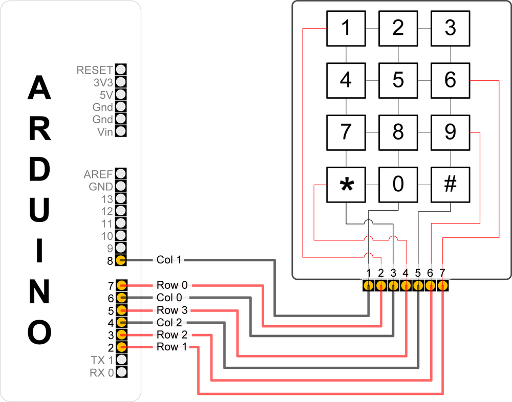
If you’ve wired your Arduino and keypad as shown in Figure 5-6, the following sketch will print key presses to the Serial Monitor:
/*
  Keypad sketch
  prints the key pressed on a keypad to the serial port
*/

const int numRows = 4;       // number of rows in the keypad
const int numCols = 3;       // number of columns
const int debounceTime = 20; // number of milliseconds for switch to be stable

// keymap defines the character returned when the corresponding key is pressed
const char keymap[numRows][numCols] = {
  { '1', '2', '3'  } ,
  { '4', '5', '6'  } ,
  { '7', '8', '9'  } ,
  { '*', '0', '#'  }
};

// this array determines the pins used for rows and columns
const int rowPins[numRows] = { 7, 2, 3, 5 }; // Rows 0 through 3
const int colPins[numCols] = { 6, 8, 4 };    // Columns 0 through 2

void setup()
{
  Serial.begin(9600);
  for (int row = 0; row < numRows; row++)
  {
    pinMode(rowPins[row],INPUT);       // Set row pins as input
    digitalWrite(rowPins[row],HIGH);   // turn on Pull-ups
  }
  for (int column = 0; column < numCols; column++)
  {
    pinMode(colPins[column],OUTPUT);     // Set column pins as outputs
                                         // for writing
    digitalWrite(colPins[column],HIGH);  // Make all columns inactive
  }
}

void loop()
{
  char key = getKey();
  if( key != 0) {       // if the character is not 0 then
                        // it's a valid key press
    Serial.print("Got key ");
    Serial.println(key);
  }
}

// returns with the key pressed, or 0 if no key is pressed
char getKey()
{
  char key = 0;                                  // 0 indicates no key pressed

  for(int column = 0; column < numCols; column++)
  {
    digitalWrite(colPins[column],LOW);         // Activate the current column.
    for(int row = 0; row < numRows; row++)     // Scan all rows for
                                               // a key press.
    {
      if(digitalRead(rowPins[row]) == LOW)     // Is a key pressed?
      {
        delay(debounceTime);                   // debounce
        while(digitalRead(rowPins[row]) == LOW)
            ;                                  // wait for key to be released
        key = keymap[row][column];             // Remember which key
                                               // was pressed.
      }
    }
    digitalWrite(colPins[column],HIGH);     // De-activate the current column.
  }
  return key;  // returns the key pressed or 0 if none
}
This sketch will only work correctly if the wiring agrees with the code. Table 5-2 shows how the rows and columns should be connected to Arduino pins. If you are using a different keypad, check your data sheet to determine the row and column connections. Check carefully, as incorrect wiring can short out the pins, and that could damage your controller chip.
Discussion
Matrix keypads typically consist of Normally Open switches that
connect a row with a column when pressed. (A Normally Open switch only
makes electrical connection when pushed.) Figure 5-6 shows how the
internal conductors connect the button rows and columns to the
keyboard connector. Each of the four rows is connected to an input pin
and each column is connected to an output pin. The setup function sets the pin modes and
enables pull-up resistors on the input pins (see the pull-up recipes
in the beginning of this chapter).
The getkey function sequentially sets the pin for each column
LOW and then checks to see if any
of the row pins are LOW. Because
pull-up resistors are used, the rows will be high (pulled up) unless a
switch is closed (closing a switch produces a LOW signal on the input pin). If they are
LOW, this indicates that the switch
for that row and column is closed. A delay is used to ensure that the
switch is not bouncing (see Recipe 5.3); the code waits
for the switch to be released, and the character associated with the
switch is found in the keymap array
and returned from the function. A 0
is returned if no switch is pressed.
A library in the Arduino Playground that is similar to the preceding example provides more functionality. The library makes it easier to handle different numbers of keys and it can be made to work while sharing some of the pins with an LCD. You can find the library at http://www.arduino.cc/playground/Main/KeypadTutorial.
See Also
For more information on the SparkFun 12-button keypad, go to http://www.sparkfun.com/commerce/product_info.php?products_id=8653.
5.6. Reading Analog Values
Problem
You want to read the voltage on an analog pin. Perhaps you want a reading from a potentiometer (pot) or a device or sensor that provides a voltage between 0 and 5 volts.
Solution
This sketch reads the voltage on an analog pin and flashes an
LED in a proportional rate to the value returned from the analogRead function. The voltage is adjusted by a potentiometer
connected as shown in Figure 5-7:
/*
 Pot sketch
 blink an LED at a rate set by the position of a potentiometer
*/

const int potPin = 0;    // select the input pin for the potentiometer
const int ledPin = 13;   // select the pin for the LED
int val = 0;             // variable to store the value coming from the sensor

void setup()
{
  pinMode(ledPin, OUTPUT);  // declare the ledPin as an OUTPUT
}

void loop() {
  val = analogRead(potPin);    // read the voltage on the pot
  digitalWrite(ledPin, HIGH); // turn the ledPin on
  delay(val);                 // blink rate set by pot value (in milliseconds)
  digitalWrite(ledPin, LOW);  // turn the ledPin off
  delay(val);                 // turn led off for same period as it was turned on
}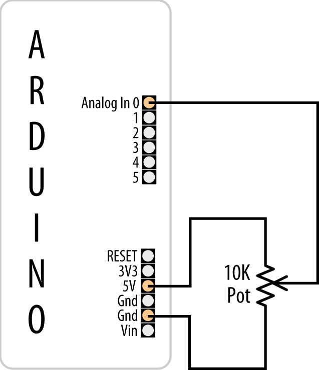
Discussion
This sketch uses the analogRead function to read the voltage on
the potentiometer’s wiper (the center
pin). A pot has three pins; two are connected to a resistive material
and the third pin (usually in the middle) is connected to a wiper that
can be rotated to make contact anywhere on the resistive material. As
the potentiometer rotates, the resistance between the wiper and one of
the pins increases, while the other decreases. The schematic diagram
for this recipe (Figure 5-7) may help you
visualize how a potentiometer works; as the wiper moves toward the
bottom end, the wiper (the line with the arrow) will have lower
resistance connecting to Gnd and higher resistance connecting to 5
volts. As the wiper moves down, the voltage on the analog pin will
decrease (to a minimum of 0 volts). Moving the wiper upward will have
the opposite effect, and the voltage on the pin will increase (up to a
maximum of 5 volts).
Note
If the voltage on the pin decreases, rather than increases, as you increase the rotation of the potentiometer, you can reverse the connections to the +5 volts and Gnd pins.
The voltage is measured using analogRead, which provides a value
proportional to the actual voltage on the analog pin. The value will
be 0 when there are 0 volts on the pin and 1,023 when there are 5
volts. A value in between will be proportional to the ratio of the
voltage on the pin to 5 volts.
Potentiometers with a value of 10K ohms are the best choice for connecting to analog pins. See this book’s website for recommended part numbers.
Note
potPin does not need to be
set as input. (This is done for you automatically each time you call
analogRead.)
See Also
Appendix B, for tips on reading schematic diagrams
Arduino reference for analogRead: http://www.arduino.cc/en/Reference/AnalogRead
Getting Started with Arduino by Massimo Banzi (Make)
5.7. Changing the Range of Values
Problem
You want to change the range of a value, such as the value
from analogRead obtained
by connecting a potentiometer (pot) or other device that provides a
variable voltage. For example, suppose you want to display the
position of a potentiometer knob as a percentage from 0 percent to 100
percent.
Solution
Use the Arduino map function
to scale values to the range you want. This sketch reads
the voltage on a pot into the variable val and scales this from 0 to 100 as the pot
is rotated from one end to the other. It blinks an LED with a rate
proportional to the voltage on the pin and prints the scaled range to
the serial port (see Recipe 4.2 for instructions on
monitoring the serial port). Recipe 5.6
shows how the pot is connected (see Figure 5-7):
/*
 * Map sketch
 * map the range of analog values from a pot to scale from 0 to 100
 * resulting in an LED blink rate ranging from 0 to 100 milliseconds.
 * and Pot rotation percent is written to the serial port
 */

const int potPin = 0;          // select the input pin for the potentiometer
int ledPin = 13;               // select the pin for the LED

void setup()
{
  pinMode(ledPin, OUTPUT);     // declare the ledPin as an OUTPUT
  Serial.begin(9600);
}

void loop() {
  int val;                       // The value coming from the sensor
  int percent;                   // The mapped value

  val = analogRead(potPin);        // read the voltage on the pot (val ranges
                                   // from 0 to 1023)
  percent = map(val,0,1023,0,100); // percent will range from 0 to 100.
  digitalWrite(ledPin, HIGH);      // turn the ledPin on
  delay(percent);                  // On time given by percent value
  digitalWrite(ledPin, LOW);       // turn the ledPin off
  delay(100 - percent);            // Off time is 100 minus On time
  Serial.println(percent);         // show the % of pot rotation on Serial Monitor
}
Discussion
Recipe 5.6 describes how the
position of a pot is converted to a value. Here you use this value
with the map function to scale the
value to your desired range. In this example, the value provided by
analogRead (0 to 1023) is mapped to a percentage (0 to 100).
The values from analogRead will
range from 0 to 1023 if the voltage ranges from 0 to 5
volts, but you can use any appropriate values for the source and
target ranges. For example, a typical pot only rotates 270 degrees
from end to end, and if you wanted to display the angle of the knob on
your pot, you could use this code:
angle = map(val,0,1023,0,270); // angle of pot derived from analogRead val
Range values can also be negative. If you want to display
0 when the pot is centered and
negative values when the pot is rotated left and positive values when
it is rotated right, you can do this:
// show angle of 270 degree pot with center as 0
angle = map(val,0,1023,-135,135);
The map function can be handy
where the input range you are concerned with does not start at zero.
For example, if you have a battery where the available capacity is
proportional to a voltage that ranges from 1.1 volts (1,100
millivolts) to 1.5 volts (1,500 millivolts), you can do the
following:
const int empty  = 5000 / 1100; // the voltage is 1.1 volts (1100mv) when empty
const int full   = 5000 / 1500; // the voltage is 1.5 volts (1500mv) when full

int val = analogRead(potPin);               // read the analog voltage
int percent = map(val, empty, full, 0,100); // map the actual range of voltage
to a percent
Serial.println(percent);
If you are using sensor readings with map then you will need to determine the
minimum and maximum values from your sensor. You can monitor the
reading on the serial port to determine the lowest and highest values.
Enter these as the lower and upper bound into the map function.
If the range can’t be determined in advance, you can determine the values by calibrating the sensor. Recipe 8.11 shows one technique for calibration; another can be found in the Calibration examples sketch distributed with Arduino (Examples→Analog→Calibration).
Bear in mind that if you feed values into map that are outside the upper and lower
limits, the output will also be outside the specified output range.
You can prevent this happening by using the constrain function; see Recipe 3.5.
Note
map uses integer math, so
it will only return whole numbers in the range specified. Any
fractional element is truncated, not rounded.
(See Recipe 5.9 for more
details on how analogRead values
relate to actual voltage.)
See Also
The Arduino reference for map: http://www.arduino.cc/en/Reference/Map
5.8. Reading More Than Six Analog Inputs
Problem
You have more analog inputs to monitor than you have available analog pins. A standard Arduino board has six analog inputs (the Mega has 16) and there may not be enough analog inputs available for your application. Perhaps you want to adjust eight parameters in your application by turning knobs on eight potentiometers.
Solution
Use a multiplexer chip to select and connect multiple voltage sources to one analog input. By sequentially selecting from multiple sources, you can read each source in turn. This recipe uses the popular 4051 chip connected to Arduino as shown in Figure 5-8. Your analog inputs get connected to the 4051 pins marked Ch 0 to Ch 7. Make sure the voltage on the channel input pins is never higher than 5 volts:
/*
 * multiplexer sketch
 * read 1 of 8 analog values into single analog input pin with 4051 multiplexer
 */

// array of pins used to select 1 of 8 inputs on multiplexer
const int select[] = {2,3,4}; // pins connected to the 4051 input select lines
const int analogPin = 0;      // the analog pin connected to multiplexer output

// this function returns the analog value for the given channel
int getValue( int channel)
{
   // set the selector pins HIGH and LOW to match the binary value of channel
   for(int bit = 0; bit < 3; bit++)
   {
      int pin = select[bit]; // the pin wired to the multiplexer select bit
      int isBitSet =  bitRead(channel, bit); // true if given bit set in channel
      digitalWrite(pin, isBitSet);
   }
   return analogRead(analogPin);
}

void setup()
{
  for(int bit = 0; bit < 3; bit++)
    pinMode(select[bit], OUTPUT);  // set the three select pins to output
  Serial.begin(9600);
}
void loop () {
  // print the values for each channel once per second
  for(int channel = 0; channel < 8; channel++)
  {
     int value = getValue(channel);
     Serial.print("Channel ");
     Serial.print(channel);
     Serial.print(" = ");
     Serial.println(value);
  }
  delay (1000);
}
Discussion
Analog multiplexers are digitally controlled analog switches. The 4051 selects one of eight inputs through three selector pins (S0, S1, and S2). There are eight different combinations of values for the three selector pins, and the sketch sequentially selects each of the possible bit patterns; see Table 5-3.
Selector pins | Selected input | ||
S2 | S1 | S0 | |
0 | 0 | 0 | 0 |
0 | 0 | 1 | 1 |
0 | 1 | 0 | 2 |
0 | 1 | 1 | 3 |
1 | 0 | 0 | 4 |
1 | 0 | 1 | 5 |
1 | 1 | 0 | 6 |
1 | 1 | 1 | 7 |
You may recognize the pattern in Table 5-3 as the binary representation of the decimal values from 0 to 7.
In the preceding sketch, getValue() is the function that sets the correct selector bits for the
given channel using digitalWrite(pin,
isBitSet) and reads the analog value from the selected 4051
input with analogRead(analogPin).
The code to produce the bit patterns uses the built-in bitRead function
(see Recipe 3.12).
Note
Don’t forget to connect the ground from the devices you are measuring to the ground on the 4051 and Arduino, as shown in Figure 5-8.
Bear in mind that this technique selects and monitors the eight
inputs sequentially, so it requires more time between the readings on
a given input compared to using analogRead directly. If you are reading
eight inputs, it will take eight times longer for each input to be
read. This may make this method unsuitable for inputs that change
value quickly.
See Also
Arduino Playground tutorial for the 4051: http://www.arduino.cc/playground/Learning/4051
CD4051 data sheet: http://www.fairchildsemi.com/ds/CD%2FCD4052BC.pdf
Analog/digital MUX breakout board data sheet: http://www.nkcelectronics.com/analogdigital-mux-breakout.html
5.9. Displaying Voltages Up to 5V
Problem
You want to monitor and display the value of a voltage between 0 and 5 volts. For example, suppose you want to display the voltage of a single 1.5V cell on the Serial Monitor.
Solution
Use AnalogRead to measure the
voltage on an analog pin. Convert the reading to a voltage by using
the ratio of the reading to the reference voltage (5 volts), as shown
in Figure 5-9.
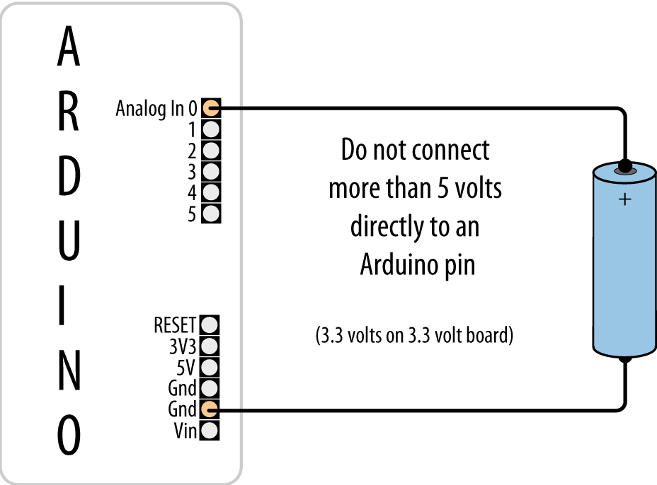
The simplest solution uses a floating-point calculation to print the voltage; this example sketch calculates and prints the ratio as a voltage:
/*
 * Display5vOrless sketch
 * prints the voltage on analog pin to the serial port
 * Warning - do not connect more than 5 volts directly to an Arduino pin.
 */

const float referenceVolts = 5.0;  // the default reference on a 5-volt board
const int batteryPin = 0;          // battery is connected to analog pin 0

void setup()
{
   Serial.begin(9600);
}

void loop()
{
   int val = analogRead(batteryPin);  // read the value from the sensor
   float volts = (val / 1023.0) * referenceVolts;  // calculate the ratio
   Serial.println(volts);  // print the value in volts
}
The formula is: Volts = (analog reading / analog steps) × Reference voltage
Printing a floating-point value to the serial port with println will format the value to two decimal
places.
Floating-point numbers consume lots of memory, so unless you are already using
floating point elsewhere in your sketch, it is more efficient to use
integer values. The following code looks a little strange at first,
but because analogRead returns a
value of 1023 for 5 volts, each
step in value will be 5 divided by 1,023. In units of millivolts, this
is 5,000 divided by 1,023.
This code prints the value in millivolts:
const int  batteryPin = 0;

void setup()
{
  Serial.begin(9600);
}

void loop()
{
  long val = analogRead(batteryPin);   // read the value from the sensor -
                                       // note val is a long int
  Serial.println( (val * (500000/1023)) / 100);  // print the value in millivolts
}
The following code prints the value using decimal points. It
prints 1.5 if the voltage is 1.5
volts:
const int batteryPin = 0;

void setup()
{
  Serial.begin(9600);
}

void loop()
{
  int val = analogRead(batteryPin); // read the value from the sensor

  long mv =  (val * (500000/1023L)) / 100; // calculate the value in millivolts
  Serial.print(mv/1000); // print the integer value of the voltage
  Serial.print('.'),
  int fraction = (mv % 1000); // calculate the fraction
  if (fraction == 0)
     Serial.print("000");      // add three zero's
  else if (fraction < 10)    // if fractional < 10 the 0 is ignored giving a wrong
                               // time, so add the zeros
     Serial.print("00");       // add two zeros
  else if (fraction < 100)
     Serial.print("0");
  Serial.println(fraction); // print the fraction
}
Note
If you are using a 3.3V board, change (1023/5) to (int)(1023/3.3).
Discussion
The analogRead() function
returns a value that is proportional to the ratio of the measured
voltage to the reference voltage (5 volts). To avoid the use of
floating point, yet maintain precision, the code operates on values as
millivolts instead of volts (there are 1,000 millivolts in 1 volt).
Because a value of 1023 indicates
5,000 millivolts, each unit represents 5,000 divided by 1,023
millivolts (that is, 4.89 millivolts).
Note
You will see both 1023 and 1024 used for converting analogRead values to millivolts. 1024 is
commonly used by engineers because there are 1024 possible values
between 0 and 1023. However, 1023 is more intuitive for some because
the highest possible value is 1023. In practice, the hardware
inaccuracy is greater than the difference between the calculations
so choose whichever value you feel more comfortable with.
To eliminate the decimal point, the values are multiplied by 100. In other words, 5,000 millivolts times 100 divided by 1,023 gives the number of millivolts times 100. Dividing this by 100 yields the value in millivolts. If multiplying fractional numbers by 100 to enable the compiler to perform the calculation using fixed-point arithmetic seems convoluted, you can stick to the slower and more memory-hungry floating-point method.
This solution assumes you are using a standard Arduino powered from 5 volts. If you are using a 3.3V board, the maximum voltage you can measure is 3.3 volts without using a voltage divider—see Recipe 5.11.
5.10. Responding to Changes in Voltage
Problem
You want to monitor one or more voltages and take some action when the voltage rises or falls below a threshold. For example, you want to flash an LED to indicate a low battery level—perhaps to start flashing when the voltage drops below a warning threshold and increasing in urgency as the voltage drops further.
Solution
You can use the connections shown in Figure 5-7 in Recipe 5.9, but here we’ll compare the
value from analogRead to see if it
drops below a threshold. This example starts flashing an LED at 1.2
volts and increases the on-to-off time as the voltage decreases below
the threshold. If the voltage drops below a second threshold, the LED stays lit:
/*
 * RespondingToChanges sketch
 * flash an LED to indicate low voltage levels
 */

long batteryFull       = 1500;  // millivolts for a full battery
long warningThreshold  = 1200;  // Warning level in millivolts - LED flashes
long criticalThreshold = 1000;  // Critical voltage level - LED stays on

const int batteryPin = 0;
const int ledPin = 13;

void setup()
{
   pinMode(ledPin, OUTPUT);
}

void loop()
{
  int val = analogRead(batteryPin);    // read the value from the sensor
  int mv = map(val, 0,1023, 0,5000);
  if(mv < criticalThreshold)
     flash(0);
  else if (mv < warningThreshold) {
    // in the line above, L following a number makes it a 32 bit value
    int percent = map(mv, criticalThreshold, batteryFull, 0, 100);
    constrain(percent, 0,100);
    flash(percent) ;
  }
  delay(1);
}

// function to flash an led with on/off time determined by value
// passed as percent
void flash(int percent)
{
  digitalWrite(ledPin, HIGH);
  delay(100 - percent +1);  // ensure delay is > 0
  digitalWrite(ledPin, LOW);
  delay(percent + 1);
}
Discussion
The highlighted line in this sketch calculates the ratio of the
value read from the analog port to the value of the threshold voltage.
For example, with a warning threshold of 1 volt and a reference voltage of 5
volts, you want to know when the analog reading is one-fifth of the
reference voltage. The expression 1023L tells the compiler that this is a long
integer (a 32-bit integer; see Recipe 2.2), so the compiler
will promote all the variables in this expression to long integers to
prevent overflowing the capacity of an int (a normal 16-bit integer).
When reading analog values, you can work in the units that are
returned from analogRead—ranging
from 0 to 1023—or you can work in the actual voltages they represent
(see Recipe 5.7). As in this
recipe, if you are not displaying voltage, it’s simpler and more
efficient to use the output of analogRead directly.
5.11. Measuring Voltages More Than 5V (Voltage Dividers)
Problem
You want to measure voltages greater than 5 volts. For example, you want to display the voltage of a 9V battery and trigger an alarm LED when the voltage falls below a certain level.
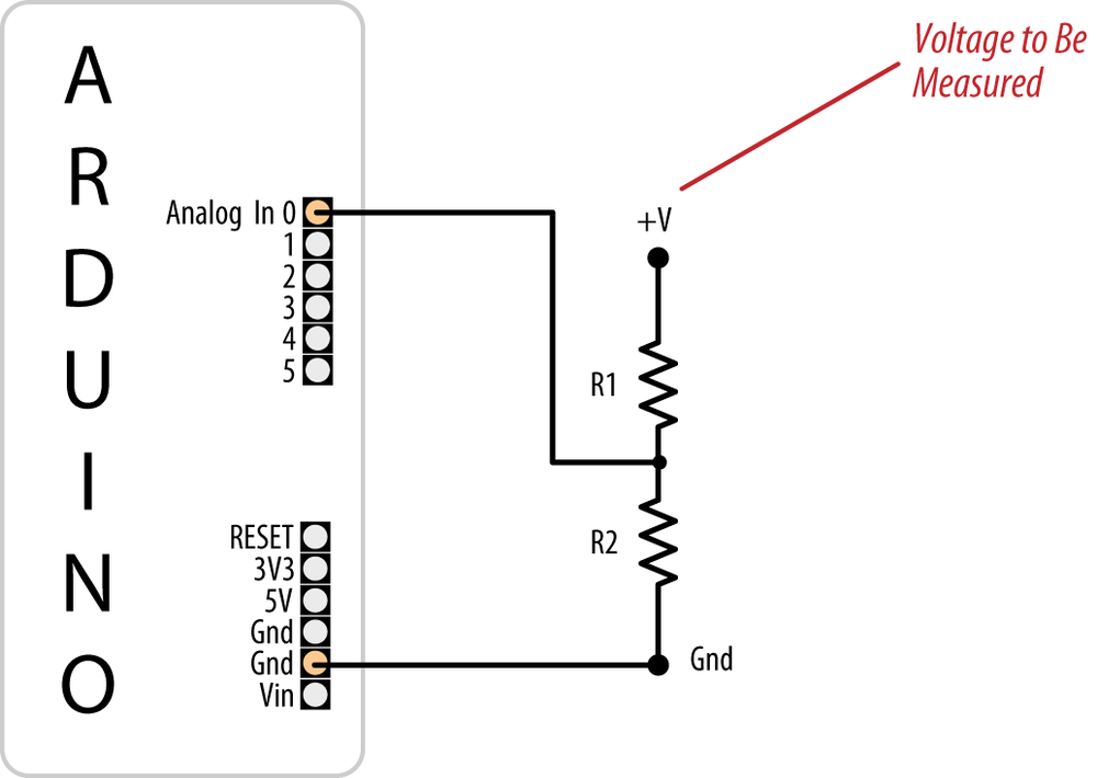
Solution
Use a solution similar to Recipe 5.9, but connect the voltage through a voltage divider (see Figure 5-10). For voltages up to 10 volts, you can use two 4.7K ohm resistors. For higher voltages, you can determine the required resistors using Table 5-4.
Max voltage | R1 | R2 | Calculation R2/(R1 + R2) | value of |
5 | Short (+V connected to analog pin) | None (Gnd connected to Gnd) | None | 1023 |
10 | 1K | 1K | 1(1 + 1) | 511 |
15 | 2K | 1K | 1(2 + 1) | 341 |
20 | 3K | 1K | 1(3 + 1) | 255 |
30 | 5K (5.1K) | 1K | 1(5 + 1) | 170 |
Select the row with the highest voltage you need to measure to find the values for the two resistors:
/*
  DisplayMoreThan5V sketch
  prints the voltage on analog pin to the serial port
  Do not connect more than 5 volts directly to an Arduino pin.
*/

const float referenceVolts = 5;        // the default reference on a 5-volt board
//const float referenceVolts = 3.3;  // use this for a 3.3-volt board

const float R1 = 1000; // value for a maximum voltage of 10 volts
const float R2 = 1000;
// determine by voltage divider resistors, see text
const float resistorFactor = 1023.0 * (R2/(R1 + R2));
const int batteryPin = 0;         // +V from battery is connected to analog pin 0

void setup()
{
   Serial.begin(9600);
}

void loop()
{
   int val = analogRead(batteryPin);  // read the value from the sensor
   float volts = (val / resistorFactor) * referenceVolts ; // calculate the ratio
   Serial.println(volts);  // print the value in volts
}
Discussion
Like the previous analog recipes, this recipe relies on the fact
that the analogRead value is
a ratio of the measured voltage to the reference. But because the
measured voltage is divided by the two dropping resistors, the
analogRead value needs to be
multiplied to get the actual voltage. The code here is similar to that
in Recipe 5.7, but the value of
resistorFactor is selected based on the voltage
divider resistors as shown in Table 5-4:
const int resistorFactor = 511;    // determine by voltage divider resistors,
see Table 5-3
The value read from the analog pin is divided not by 1,023, but by a value determined by the dropping resistors:
float volts = (val / resistorFactor) * referenceVolts ; // calculate the ratioThe calculation used to produce the table is based on the
following formula: the output voltage is equal to the input voltage
times R2 divided by the sum of R1 and R2. In the example where two
equal-value resistors are used to drop the voltage from a 9V battery
by half, resistorFactor is 511
(half of 1,023), so the value of the volts variable will be twice the voltage
that appears on the input pin. With resistors selected for 10 volts,
the analog reading from a 9V battery will be approximately 920.
Warning
More than 5 volts on the pin can damage the pin and possibly destroy the chip; double-check that you have chosen the right value resistors and wired them correctly before connecting them to an Arduino input pin. If you have a multimeter, measure the voltage before connecting anything that could possibly carry voltages higher than 5 volts.