
7
Expanding Your Arduino
In this chapter you will
- Learn about the broad variety of Arduino shields
- Make your own Arduino shield using a ProtoShield
- See how Arduino libraries can expand the available functions
- Use a memory card module to record data that can be analyzed in a spreadsheet
- Build a temperature-logging device
- Learn how to make a stopwatch using
micros()andmillis() - Understand Arduino interrupts and their uses
Another way to expand the capabilities of your Arduino is by using shields. A shield is a circuit board that connects via pins to the sockets on the sides of an Arduino. In the first project in this chapter, you’ll learn how to make your own shield. Over time, as you experiment with electronics and Arduino, you can make your circuits more permanent by building them onto a ProtoShield, a blank printed circuit board that you can use to mount custom circuitry.
Next, I’ll introduce a memory card module. We’ll use it in this chapter to create a temperature-logging device to record temperatures over time; the shield will be used to record data from the Arduino to be transferred elsewhere for analysis.
You’ll learn about the functions micros() and millis(), which are very useful for keeping time, as you’ll see in the stopwatch project. Finally, we’ll examine interrupts.
Shields
You can add functionality to your Arduino board by attaching shields. Hundreds of shields are available on the market, and they can be combined, or stacked, to work together. One popular project, for example, combines a GPS shield with a microSD memory card shield to create a device that logs and stores position over time, for example to record a car’s path of travel or the location of a new hiking trail. Other projects include Ethernet network adapters that let the Arduino access the internet (Figure 7-1).

Figure 7-1: An Ethernet shield on an Arduino Uno
GPS satellite receivers let you track the location of the Arduino (Figure 7-2). MicroSD memory card interfaces let the Arduino store data on a memory card (Figure 7-3).
Figure 7-4 shows a stack that includes an Arduino Uno, a microSD memory card shield to which data can be recorded, an Ethernet shield for connecting to the internet, and an LCD shield to display information.

Figure 7-2: A GPS receiver shield (with separate GPS module)
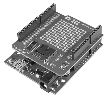
Figure 7-3: A MicroSD card shield

Figure 7-4: Three stacked shields with an Arduino Uno
ProtoShields
You can buy a variety of shields online, or make your own using a ProtoShield. A ProtoShield is a blank circuit board that you can use to make your own permanent Arduino shields. ProtoShields come preassembled or in kit form, similar to the one shown in Figure 7-5.
A ProtoShield also makes a good base for a solderless breadboard, because it keeps a small circuit within the physical boundary of your Arduino creation (as shown in Figure 7-6). Smaller solderless breadboards fit within the rows of sockets and can be temporarily mounted on the circuit board with Blu Tack reusable putty or mounted more permanently with double-sided tape. ProtoShields can also act as a more permanent foundation for circuits that have been tested on a breadboard.

Figure 7-5: A ProtoShield kit
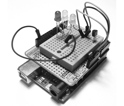
Figure 7-6: An example of small project mounted on a ProtoShield’s solderless breadboard
Building custom circuits on a ProtoShield requires some forward planning. You have to design the circuit, make a schematic, and then plan the layout of the components as they will sit on the ProtoShield. Finally, you will solder the completed circuit onto your custom shield, but you should always test it first using a solderless breadboard to ensure that it works. Some ProtoShields come with a PDF schematic file that you can download and print, intended specifically for drawing your project schematic.
Project #21: Creating a Custom Shield
In this project, you’ll create a custom shield containing two LEDs and current-limiting resistors. This custom shield will make it easy to experiment with LEDs on digital outputs.
The Hardware
The following hardware is required for this project:
- One blank Arduino ProtoShield with stacking headers
- Two LEDs of any color
- Two 560 Ω resistors
- Two 10 kΩ resistors
- Two push buttons
- Two 100 nF capacitors
The Schematic
The circuit schematic is shown in Figure 7-7.

Figure 7-7: Schematic for Project 21
The Layout of the ProtoShield Board
The next step is to learn the layout of the holes on the ProtoShield. The rows and columns of holes on the ProtoShield generally match those of a solderless breadboard. However, each ProtoShield may vary, so take the time to determine how the holes are connected. On the example ProtoShield shown in Figure 7-8, some holes are connected, as shown by the solid lines between the holes, but a lot of holes have been left unconnected. This design gives you a lot of flexibility in how you use your ProtoShield.

Figure 7-8: A blank ProtoShield shown from above
Note the two groups of holes surrounded by rectangles along the top and bottom of the ProtoShield: this is where we solder the stackable headers that allow the ProtoShield to slot into the Arduino board.
The Design
You need to convert the circuit shown in Figure 7-7 into a physical layout that’s suitable for your ProtoShield. A good way to do this is to lay out your circuit using graph paper, as shown in Figure 7-9. You can then mark the connected holes on the graph paper and easily experiment until you find a layout that works for your particular ProtoShield. If you don’t have any graph paper, you can generate and print your own at http://www.printfreegraphpaper.com/.

Figure 7-9: Planning our custom shield
After you’ve drawn a plan for your circuit, test-fit the components into the ProtoShield to make sure that they’ll fit and that they aren’t too crowded. If the ProtoShield has space for a reset button, always include one, because the shield will block access to your Arduino’s RESET button.
Soldering the Components
Once you’re satisfied with the layout of the circuit on your ProtoShield and you’ve tested the circuit to make sure it works, you can solder the components. Using a soldering iron is not that difficult, and you don’t need to buy an expensive soldering station for this type of work. A simple iron rated at 25 to 40 watts, like the one shown in Figure 7-10, should do the job.

Figure 7-10: Soldering iron
When soldering the components, you may need to bridge them together with a small amount of solder and wire cutoffs, as shown in Figure 7-11.
Check each solder connection as you go, because mistakes are easier to locate and repair before the project is finished. When the time comes to solder the four header sockets or header pins, keep them aligned by using an existing shield to hold the new pins, as shown in Figure 7-12.

Figure 7-11: A solder bridge

Figure 7-12: Soldering header pins
Figure 7-13 shows the finished product: a custom Arduino shield with two LEDs and two buttons.

Figure 7-13: The completed custom shield
Testing Your ProtoShield
Before moving on, it’s a great idea to test your ProtoShield’s buttons and LEDs. The sketch in Listing 7-1 uses the two buttons to turn the LEDs on or off.
// Listing 7-1: ProtoShield test
void setup()
{
  pinMode(2, INPUT);
  pinMode(3, INPUT);
  pinMode(5, OUTPUT);
  pinMode(6, OUTPUT);
}

void loop()
{
  if (digitalRead(2) == HIGH)
  {
    digitalWrite(5, HIGH);
    digitalWrite(6, HIGH);
  }
  if (digitalRead(3) == HIGH)
  {
    digitalWrite(5, LOW);
    digitalWrite(6, LOW);
  }
}
Listing 7-1: Testing the ProtoShield’s buttons and lights
Expanding Sketches with Libraries
Just as an Arduino shield can expand our hardware, a library can add useful functions to our sketches. These functions can allow us to use hardware specific to a manufacturer’s shield. Anyone can create a library, just as suppliers of various Arduino shields often write their own libraries to match their hardware.
The Arduino IDE already includes a set of preinstalled libraries. To include them in your sketches, choose Sketch▶Include Library. You should see the collection of preinstalled libraries with names such as Ethernet, LiquidCrystal, Servo, and so on. Many of these names will be self-explanatory. (If a library is required for a project in this book, it will be explained in detail in these pages.)
If you buy a new piece of hardware, you’ll generally need to download and install its libraries from the hardware vendor’s site or from a provided link. There are two methods for installing an Arduino library: downloading the library in a ZIP file or using the Arduino Library Manager. Let’s see how both methods work by walking through a download of the library required by the microSD card shield (Figure 7-3).
Downloading an Arduino Library as a ZIP File
First, let’s try downloading and installing a library in ZIP format. You’ll download the advanced library used by memory card modules to allow you to read and write data to microSD and SD cards:
- Visit https://github.com/greiman/SdFat/ and click Code. Make sure HTTPS is selected and then click Download ZIP, as demonstrated in Figure 7-14.

Figure 7-14: Library download page
- After a moment, the file SdFat-master.zip will appear in your Downloads folder, as shown in Figure 7-15. If you are using an Apple computer, the ZIP file may be extracted automatically.

Figure 7-15: Downloads folder containing SdFat-master.zip
- Open the Arduino IDE and choose Sketch▶Include Library▶Add .ZIP Library, as shown in Figure 7-16.

Figure 7-16: Starting the library installation process
You will be presented with a file manager dialog, as shown in Figure 7-17. Navigate to your Downloads folder (or wherever you saved the ZIP file) and click Open.

Figure 7-17: Locating the ZIP file
The Arduino IDE will now take care of the library installation. After a few moments, you will be notified that the library has been installed by a message in the IDE output window, as shown in Figure 7-18.

Figure 7-18: Arduino library installation success
- You can verify that the SdFat library has been installed and is available by searching through the IDE’s Library Manager. To do this, click the Library Manager icon in the vertical group on the left of the IDE, then search using the box at the top, or scroll down until you see your library. For example, in Figure 7-19 you can see that SdFat appears in the Library Manager.

Figure 7-19: Successful installation of the SdFat library
Importing an Arduino Library with Library Manager
The alternative method of installing an Arduino library is via the Arduino IDE’s built-in Library Manager. This is a tool for accessing an online repository of libraries that are available for use by the wider public and have been personally approved by the Arduino team, or are just very popular. You will generally access the Library Manager when instructed to by a hardware supplier.
As an example, we’ll download the FastLED Arduino library, which is used by a popular type of RGB LED.
To do this, open the Arduino IDE if you’ve not already done so, then open the Library Manager. Enter FastLED in the search box at the top of the manager, as shown in Figure 7-20. As you type, the manager will return libraries that match your search data, and you can see the required library has appeared.

Figure 7-20: Searching the Library Manager
Once the library is found and displayed in the Library Manager, move your mouse cursor over the library description. You may have the option to select a version number. Generally, the latest version is displayed by default, so you simply need to click Install and wait for installation to complete. Installation progress is shown in the output window, as shown in Figure 7-21.

Figure 7-21: Library installation process
You can check that the library has been installed using the method described earlier in this chapter.
SD Memory Cards
By using SD or microSD cards with your Arduino, you can capture data from many sources, such as the TMP36 temperature sensor we used in Chapter 4. You can also use the cards to store web server data or any files that your project might use. To record and store the data you collect, you can use a memory card like the one shown in Figure 7-22.

Figure 7-22: A microSD card with 16GB capacity
Both microSD and SD memory cards are available to work with your Arduino.
Connecting the Card Module
Before you can use the memory card, you’ll need to connect six wires from the card reader module to your Arduino. Both card reader types (microSD and SD) will have the same pins, which should be labeled as shown in Figure 7-23.

Figure 7-23: SD card module
Make the connections between your Arduino and the card reader as shown in Table 7-1.
Table 7-1: Connections Between the Card Module and Arduino
| Module pin label | To Arduino pin | Module pin functions |
| 5 V or Vcc | 5 V | Power |
| GND | GND | GND |
| CS | D10 | Chip select |
| MOSI | D11 | Data in from Arduino |
| MISO | D12 | Data out to Arduino |
| SCK | D13 | Clock |
Testing Your SD Card
After you have finished connecting the card module to your Arduino—and you have a new or newly formatted card—now is the time to make sure the card is working correctly. To do so, follow these steps:
- Insert the memory card into the card module. Then connect the module to the Arduino and the Arduino to your PC via the USB cable.
- Open the IDE and select File▶Examples▶SdFat▶SdInfo. This will load an example sketch.
- Scroll down to line 36 in the sketch and change the value of
const int chipSelectfrom4to10, as shown in Figure 7-24. This is necessary as the pin used varies depending on the SD card hardware. Now upload this sketch to your Arduino.
Figure 7-24: Altering the test sketch
- Finally, open the Serial Monitor window, set it to 9,600 baud, press any key on the keyboard, and press enter. After a moment, you should see some data about the microSD card, as shown in Figure 7-25.

Figure 7-25: Results of a successful memory card test
If the test results don’t appear in the Serial Monitor, try the following:
- Remove the USB cable from your Arduino and remove and reinsert the microSD card.
- Make sure that the wiring connections match those in Table 7-1.
- Check that the Serial Monitor baud rate is 9,600 and that a regular Arduino Uno–compatible board is being used. The Mega and some other board models have the SPI pins in different locations.
- Reformat your memory card.
- Failing all else, try a new name-brand memory card.
Finally, before either inserting your memory card or removing it, ensure the entire project is disconnected from the USB and/or power supply.
Project #22: Writing Data to the Memory Card
In this project, you’ll use a memory card to store data—specifically, a multiplication table.
The Sketch
To write data to the memory card, connect your shield, insert a microSD card, and then enter and upload the following sketch:
// Project 22 - Writing Data to the Memory Card
#include <SD.h>
int b = 0;
void setup()
{
  Serial.begin(9600);
  Serial.println("Initializing SD card...");
  pinMode(10, OUTPUT);

  // check that the memory card exists and is usable
  if (!SD.begin(10))
  {
    Serial.println("Card failed, or not present");
    // stop sketch
    return;
  }
  Serial.println("memory card is ready");
}

void loop()
{
1   // create the file for writing
  File dataFile = SD.open("DATA.TXT", FILE_WRITE);
  // if the file is ready, write to it:
  if (dataFile)
2   {
    for ( int a = 0 ; a < 11 ; a++ )
    {
      dataFile.print(a);
      dataFile.print(" multiplied by two is ");
      b = a * 2;
3       dataFile.println(b, DEC);
  }
4     dataFile.close(); // close the file once the system has finished with it
                      // (mandatory)
  }
  // if the file isn't ready, show an error:
  else
  {
    Serial.println("error opening DATA.TXT");
  }
  Serial.println("finished");
  do {} while (1);
}
Figure 7-26: Output from Project 22
The sketch creates a text file called DATA.TXT on the microSD card, as shown in Figure 7-26.
Let’s review the void loop() section of the sketch to see how it created the text file. The code in void loop() between 1 and 2 creates and opens the file for writing. To write text to the file, we use dataFile.print() or dataFile.println().
This code works in the same manner as, for example, Serial.println(), so you can write it in the same manner as you would to the Serial Monitor. At 1 we set the name of the created text file, which must be eight characters or less, followed by a dot, and then three characters, such as DATA.TXT.
At 3, we use DEC as the second parameter. This states that the variable is a decimal number and should be written to the text file as such. If we were writing a float variable instead, then we would use a digit for the number of decimal places to write (to a maximum of six).
When we’re finished writing data to the file, at 4, we use dataFile.close() to close the file for writing. If this step is not followed, the computer will not be able to read the created text file.
Project #23: Creating a Temperature-Logging Device
Now that you know how to record data, let’s measure and record the temperature every minute for 8 hours using our memory card setup from Project 22 and the TMP36 temperature sensor circuit introduced in Chapter 4.
The Hardware
The following hardware is required:
- One TMP36 temperature sensor
- One breadboard
- Various connecting wires
- Memory card and module
- Arduino and USB cable
Insert the microSD card into the shield, and then insert the shield into the Arduino. Connect the left (5 V) pin of the TMP36 to Arduino 5 V, the middle pin to analog, and the right pin to GND.
The Sketch
Enter and upload the following sketch:
// Project 23 - Creating a Temperature-Logging Device

#include <SD.h>
float sensor, voltage, celsius;

void setup()
{
  Serial.begin(9600);
  Serial.println("Initializing SD card...");
  pinMode(10, OUTPUT);

  // check that the memory card exists and can be used
  if (!SD.begin(10))
  {
    Serial.println("Card failed, or not present");
    // stop sketch
    return;
  }
  Serial.println("memory card is ready");
}
void loop()
{
  // create the file for writing
  File dataFile = SD.open("DATA.TXT", FILE_WRITE);
  // if the file is ready, write to it:
  if (dataFile)
  {
    for ( int a = 0 ; a < 481 ; a++ ) // 480 minutes in 8 hours
    {
      sensor = analogRead(0);
      voltage = (sensor * 5000) / 1024; // convert raw sensor value to
                                        // millivolts
      voltage = voltage - 500;
      celsius = voltage / 10;
      dataFile.print(" Log: ");
      dataFile.print(a, DEC);
      dataFile.print(" Temperature: ");
      dataFile.print(celsius, 2);
      dataFile.println(" degrees C");
      delay(599900); // wait just under one minute
    }
    dataFile.close(); // mandatory
    Serial.println("Finished!");
    do {} while (1);
  }
}
The sketch will take a little more than 8 hours to complete, but you can alter this period by lowering the value in delay(599900).
After the sketch has finished, remove the microSD card from the Arduino, insert it into your computer, and open the log file in a text editor, as shown in Figure 7-27.

Figure 7-27: Results from Project 23
For more serious analysis of the captured data, delimit the lines of text written to the log file with spaces or colons so that the file can be easily imported into a spreadsheet. For example, you could import the file into OpenOffice Calc or Excel to produce a spreadsheet like the one shown in Figure 7-28.

Figure 7-28: Importing the data into a spreadsheet
Then you can easily perform some statistical analysis of the data, as shown in Figure 7-29.
The temperature examples can be hacked to suit your own data analysis projects. You can use these same concepts to record any form of data that can be generated by an Arduino system.

Figure 7-29: Temperature analysis
Timing Applications with millis() and micros()
Each time the Arduino starts running a sketch, it also records the passage of time using milliseconds and microseconds. A millisecond is one thousandth of a second (0.001), and a microsecond is one millionth of a second (0.000001). You can use these values to measure the passage of time when running sketches.
The following functions will access the time values stored in an unsigned long variable:
  unsigned long a,b;
  a = micros();
  b = millis();
Due to the limitations of the unsigned long variable type (which stores only positive values), the value will reset to 0 after reaching 4,294,967,295, allowing for around 50 days of counting using millis() and 70 minutes using micros(). Furthermore, due to the limitations of the Arduino’s microprocessor, micros() values are always a multiple of four.
Let’s use these values to see how long it takes for the Arduino to turn a digital pin from low to high and vice versa. To do this, we’ll read micros() before and after a digitalWrite() function, find the difference, and display it in the Serial Monitor. The only required hardware is your Arduino and cable.
Enter and upload the sketch shown in Listing 7-2.
// Listing 7-2

unsigned long starting, finished, elapsed;

void setup()
{
  Serial.begin(9600);
  pinMode(3, OUTPUT);
  digitalWrite(3, LOW);
}

void loop()
{
1   starting = micros();
  digitalWrite(3, HIGH);
2   finished = micros();
3   elapsed = finished – starting;
  Serial.print("LOW to HIGH: ");
  Serial.print(elapsed);
  Serial.println(" microseconds");
  delay(1000);

4   starting = micros();
  digitalWrite(3, LOW);
  finished = micros();
  elapsed = finished - starting;
  Serial.print("HIGH to LOW: ");
  Serial.print(elapsed);
  Serial.println(" microseconds");
  delay(1000);
}
Listing 7-2: Timing digital pin state change with micros()
The sketch takes readings of micros() before and after the digitalWrite(HIGH) function call, at 1 and 2, and then it calculates the difference and displays it in the Serial Monitor at 3. This is repeated for the opposite function at 4.
Now open the Serial Monitor to view the results, shown in Figure 7-30.

Figure 7-30: Output from Listing 7-2
Because the resolution is 4 microseconds, if the value is 8 microseconds, we know that the duration is greater than 4 and less than or equal to 8.
Project #24: Creating a Stopwatch
Now that we can measure the elapsed time between two events, we can create a simple stopwatch using an Arduino. Our stopwatch will use two buttons: one to start or reset the count and one to stop counting and show the elapsed time. The sketch will continually check each button’s status. When the start button is pressed, a millis() value will be stored, and when the stop button is pressed, a new millis() value will be stored. The custom function displayResult() will convert the elapsed time from milliseconds into hours, minutes, and seconds. Finally, the time will be displayed in the Serial Monitor.
The Hardware
Use the ProtoShield as described earlier in this chapter and the following additional hardware:
- One breadboard
- Two push buttons (S1 and S2)
- Two 10 kΩ resistors (R1 and R2)
- Various connecting wires
- Arduino and USB cable
The Schematic
The circuit schematic is shown in Figure 7-31.

Figure 7-31: Schematic for Project 24
The Sketch
Enter and upload this sketch:
// Project 24 – Creating a Stopwatch

unsigned long starting, finished, elapsed;

void setup()
{
  Serial.begin(9600);
1   pinMode(2, INPUT); // the start button
  pinMode(3, INPUT); // the stop button
  Serial.println("Press 1 for Start/reset, 2 for elapsed time");
}

void displayResult()
{
  float h, m, s, ms;
  unsigned long over;

2   elapsed = finished - starting;

  h    = int(elapsed / 3600000);
  over = elapsed % 3600000;
  m    = int(over / 60000);
  over = over % 60000;
  s    = int(over / 1000);
  ms   = over % 1000;

  Serial.print("Raw elapsed time: ");
  Serial.println(elapsed);
  Serial.print("Elapsed time: ");
  Serial.print(h, 0);
  Serial.print("h ");
  Serial.print(m, 0);
  Serial.print("m ");
  Serial.print(s, 0);
  Serial.print("s ");
  Serial.print(ms, 0);
  Serial.println("ms");
  Serial.println();
}

void loop()
{
3   if (digitalRead(2) == HIGH)
  {
    starting = millis();
    delay(200); // for debounce
    Serial.println("Started...");
  }
4   if (digitalRead(3) == HIGH)
  {
    finished = millis();
    delay(200); // for debounce
    displayResult();
  }
}
The basis for our stopwatch is simple. At 1, we set up the digital input pins for the start and stop buttons. At 3, if the start button is pressed, then the Arduino notes the value for millis() that we use to calculate the elapsed time once the stop button is pressed at 4. After the stop button is pressed, the elapsed time is calculated in the function displayResult() at 2 and shown in the Serial Monitor window.
You should see results like those in Figure 7-32 in the Serial Monitor.
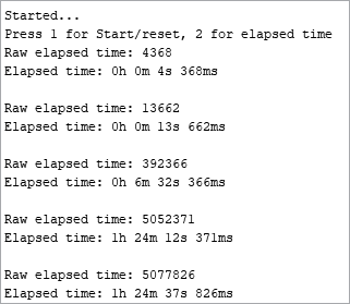
Figure 7-32: Output from Project 24
Interrupts
An interrupt in the Arduino world is basically a signal that allows a function to be called at any time within a sketch—for example, when a digital input pin’s state changes or a timer event is triggered. Interrupts are perfect for calling a function to interrupt the normal operation of a sketch, such as when a button is pressed. This type of function is often referred to as an interrupt handler.
When an interrupt is triggered, the normal operation and running of your program is halted temporarily as the interrupt function is called and executed. Then, when the interrupt function exits, whatever was happening in the program continues exactly where it left off.
Interrupt functions should be short and simple. They should exit quickly, and keep in mind that if the interrupt function does something that the main loop is already doing, then the interrupt function is going to temporarily override the main loop’s activity before the main loop resumes. For example, if the main loop is regularly sending Hello out the serial port and the interrupt function sends --- when it is triggered, then you could see any of these come out the serial port: H----ello, He----llo, Hel----lo, Hell----o, or Hello----.
The Arduino Uno offers two interrupts that are available using digital pins 2 and 3. When properly configured, the Arduino will monitor the voltage applied to the pins. When the voltage changes in a certain defined way (when a button is pressed, for example), an interrupt is triggered, causing a corresponding function to run—maybe something that sends “Stop Pressing Me!”
Interrupt Modes
One of four changes (or modes) can trigger an interrupt:
LOWNo current is applied to the interrupt pin.CHANGEThe current changes, either between on and off or between off and on.RISINGThe current changes from off to on at 5 V.FALLINGThe current changes from on at 5 V to off.
For example, to detect when a button attached to an interrupt pin has been pressed, you could use the RISING mode. Or, for example, if you had an electric trip wire running around your garden (connected between 5 V and the interrupt pin), then you could use the FALLING mode to detect when the wire has been tripped and broken.
Configuring Interrupts
To configure interrupts, use the following in void setup():
  attachInterrupt(0, function, mode);
  attachInterrupt(1, function, mode);
Here, 0 is for digital pin 2, 1 is for digital pin 3, function is the name of the function to call when the interrupt is triggered, and mode is one of the four modes that triggers the interrupt.
Activating or Deactivating Interrupts
Sometimes you won’t want to use the interrupts within a sketch. You can deactivate a single interrupt using:
detachInterrupt(digitalPinToInterrupt(pin))where pin is the digital pin number used. Or you can deactivate them all using the following:
noInterrupts(); // deactivate interruptsAnd then reactivate them with this:
interrupts(); // reactivate interruptsInterrupts work quickly and they are very sensitive. These qualities make them useful for time-critical applications or for “emergency stop” buttons on projects.
Project #25: Using Interrupts
We’ll use the circuit from Project 24 to demonstrate the use of interrupts. Our example will blink the built-in LED every 500 milliseconds, during which time both interrupt pins will be monitored. When the button on interrupt 0 is pressed, the value for micros() will be displayed in the Serial Monitor, and when the button on interrupt 1 is pressed, the value for millis() will be displayed.
The Sketch
Enter and upload the following sketch:
// Project 25 – Using Interrupts

#define LED 13
void setup()
{
  Serial.begin(9600);
  pinMode(13, OUTPUT);
  attachInterrupt(0, displayMicros, RISING);
  attachInterrupt(1, displayMillis, RISING);
}
1 void displayMicros()
{
  Serial.write("micros() = ");
  Serial.println(micros());
}

2 void displayMillis()
{
  Serial.write("millis() = ");
  Serial.println(millis());
}

3 void loop()
{
  digitalWrite(LED, HIGH);
  delay(500);
  digitalWrite(LED, LOW);
  delay(500);
}
This sketch will blink the onboard LED as shown in void loop() at 3. When interrupt 0 is triggered, the function displayMicros() at 1 will be called; when interrupt 1 is triggered, the function displayMillis() at 2 will be called. After either function has finished, the sketch resumes running the code in void loop().
Open the Serial Monitor window and press the two buttons to view the values for millis() and micros(), as shown in Figure 7-33.

Figure 7-33: Output from Project 25
Looking Ahead
This chapter has given you more tools and options that you can adapt to create and improve your own projects. In future chapters, we will work with more Arduino shields, use interrupts for timing projects, and use the memory card module in other data-logging applications.