8
LED Numeric Displays and Matrices
In this chapter, you will
- Use MAX7219-based numeric LED displays
- Build your own digital stopwatch timer
- Use MAX7219-based LED matrix modules
- Build a scrolling text LED display
Although LED numeric displays (such as those found in contemporary digital alarm clocks) may not be on the bleeding edge of display technology, they are easy to read and—more importantly—easy to use with our Arduino boards.
You learned how to use one- and two-digit LED numeric displays in Chapter 6. However, using more than two digits at a time can become messy—there’s a lot more wiring, more control ICs, and so on to take care of. Fortunately, there’s a popular IC that can control up to 64 LEDs (eight digits of a numeric display) with only three control wires from our Arduino: the MAX7219 LED driver IC from Maxim Integrated.
The MAX7219 is available in both a through-hole package type, which means it has metal legs that can fit into a circuit board or a solderless breadboard (Figure 8-1), and a surface-mount package type (Figure 8-2).

Figure 8-1: The MAX7219 in a through-hole package type

Figure 8-2: The MAX7219 in a surface-mount package type
In this chapter, you’ll learn how to use the MAX7219 to control up to eight numeric LED digits. You’ll also learn how to use the MAX7219 to control interesting LED matrix modules that allow for scrolling text displays.
LED Numeric Displays
LED numeric displays that use the MAX7219 come in many shapes and sizes, usually with four to eight digits fitted to the module. For our examples, we’re using an eight-digit module, which is easily available and great value for the money (see Figure 8-3).

Figure 8-3: The eight-digit LED module
These modules have the surface-mount version of the MAX7219, shown in Figure 8-2, on the back. The modules usually include some inline header pins to allow for attaching control wires. If you haven’t already done so, solder these to your module, as shown in Figure 8-4.
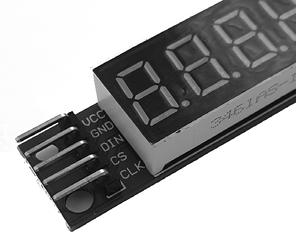
Figure 8-4: Inline header pins connected to an eight-digit LED module
Before you can use the numeric display, you’ll need to connect five wires to both the display and the Arduino. This is easily done by connecting male-to-female jumper wires to the header pins that you soldered to the board. Make the connections as shown in Table 8-1.
Table 8-1: Connections Between the Display Module and Arduino
| Module pin label | Arduino pin | Module pin function |
| Vcc | 5V | Power (+) |
| GND | GND | Power (−) or ground |
| DIN | D12 | Data in |
| CS | D10 | Chip select |
| CLK | D11 | Clock signal |
Installing the Library
There are several Arduino libraries for the MAX7219. These libraries vary according to the configuration of the display module used. We will use the LedControl library. You will need to download the library ZIP file from https://github.com/wayoda/LedControl/. Click Clone or Download and then Download ZIP, as shown in Figure 8-5.

Figure 8-5: Downloading the LedControl library
Once you have the ZIP file, install it as described in Chapter 7. Next, to use the display module, we will first examine a demonstration sketch that uses the required functions. Enter and upload the basic sketch shown in Listing 8-1.
// Listing 8-1
1 #include "LedControl.h"   // need the library
LedControl lc = LedControl(12, 11, 10, 1);
void setup()
{
2   lc.shutdown(0, false);  // enable display
  lc.setIntensity(0, 3);  // set brightness
  lc.clearDisplay(0);     // clear screen
}

void loop()
{
  // numbers with decimal point
  for (int a = 0; a < 8; a++)
  {
3     lc.setDigit(0, a, a, true);
    delay(500);
    lc.clearDisplay(0) ;  // clear screen
  }
  // dashes
  for (int a = 0; a < 8; a++)
  {
4     lc.setChar(0, a, '-', false);
    delay(500);
    lc.clearDisplay(0) ;  // clear screen
  }
  // numbers without decimal point
  for (int a = 0; a < 8; a++)
  {
    lc.setDigit(0, a, a, false);
    delay(500);
    lc.clearDisplay(0) ;  // clear screen
  }
5   // display "abcdef"
  lc.setDigit(0, 5, 10, false);
  lc.setDigit(0, 4, 11, false);
  lc.setDigit(0, 3, 12, false);
  lc.setDigit(0, 2, 13, false);
  lc.setDigit(0, 1, 14, false);
  lc.setDigit(0, 0, 15, false);
  delay(500);
  lc.clearDisplay(0) ;    // clear screen
}
Listing 8-1: Display module demonstration sketch
Let’s take a look at how the sketch in Listing 8-1 works. At 1, we include the necessary code to load the library for the display module. The LedControl() function has four parameters:
LedControl lc = LedControl(12, 11, 10, 1);The first three say which digital pins are connected (see Table 8-1), and the fourth parameter is the number of display modules connected to the Arduino—in this case one. (You can daisy-chain more than one module.)
At 2, we have three functions that control aspects of the display. The first one turns the display on or off:
lc.shutdown(0, false); The first parameter is the display. We use 0 because only one display is connected. If you have connected multiple displays, the second is display 1, the third is display 2, and so on. The second parameter specifies whether the display is on or off: false for on, true for off.
The second function is used to set the brightness of the LEDs in the display:
lc.setIntensity(0, 3); The first parameter is the display number. The second is the brightness, which can be between 0 and 15 inclusive.
The third function simply turns all the LEDs off:
lc.clearDisplay(0); This is great for clearing previously displayed data.
At 3, we display a digit on the screen using setDigit():
lc.setDigit(0, a, b, true);The first parameter is the display number. The second is the physical position of the digit on the display; for an eight-digit display, this value ranges from 7 (the leftmost digit) to 0 (the rightmost digit). The third parameter is the actual number to display (0 to 9). If you use 10 to 16, you can display the letters A to F, as we’ve done at 5. Finally, the fourth parameter controls the decimal point: true for on and false for off.
You can also write the characters A to F, H, L, P, dash, period, and underscore using setChar(), as at 4:
lc.setChar(0, a, '-', false);The parameters are the same, except you enclose the character with single quotes.
Now that we’ve been through all the commands for showing numbers and characters on the display, let’s put them into action.
Project #26: Digital Stopwatch
You learned about timing in Project 24 in Chapter 7, and you’ve just learned how to use a display module, so now you can combine these concepts to create a digital stopwatch. While not accurate to Olympic timing levels, this is a fun and useful project. Your stopwatch will be able to display milliseconds, seconds, minutes, and up to nine hours.
You will need to connect the ProtoShield (or equivalent circuit) as described in Chapter 7 and to the numeric display used earlier in this chapter. Then just upload the following sketch:
// Project 26 – Digital Stopwatch
#include "LedControl.h"   // need the library
LedControl lc = LedControl(12, 11, 10, 1);
unsigned long starting, finished, elapsed;
void setup()
{
  pinMode(2, INPUT);      // the start button
  pinMode(3, INPUT);      // the stop button
  lc.shutdown(0, false);  // enable display
  lc.setIntensity(0, 3);  // set brightness
  lc.clearDisplay(0);     // clear screen
  starting = millis();
}

1 void displayResultLED()
{
  float h, m, s, ms;
  int m1, m2, s1, s2, ms1, ms2, ms3;
  unsigned long over;
  finished = millis();
  elapsed = finished - starting;

2   h = int(elapsed / 3600000);
  over = elapsed % 3600000;
  m = int(over / 60000);
  over = over % 60000;
  s = int(over / 1000);
  ms = over % 1000;

3   // display hours
  lc.setDigit(0, 7, h, true);

  // display minutes
  m1 = m / 10;
  m2 = int(m) % 10;
  lc.setDigit(0, 6, m1, false);
  lc.setDigit(0, 5, m2, true);

  // display seconds
  s1 = s / 10;
  s2 = int(s) % 10;
  lc.setDigit(0, 4, s1, false);
  lc.setDigit(0, 3, s2, true);

  // display milliseconds (1/100 s)
  ms1 = int(ms / 100);
  ms2 = (int((ms / 10)) % 10);
  ms3 = int(ms) % 10;
  lc.setDigit(0, 2, ms1, false);
  lc.setDigit(0, 1, ms2, false);
  lc.setDigit(0, 0, ms2, false);
}

void loop()
{
4   if (digitalRead(2) == HIGH)  // reset count
  {
    starting = millis();
    delay(200);                // for debounce

  }
5   if (digitalRead(3) == HIGH)  // display count for five seconds then resume
  {
    finished = millis();
    delay(5000);               // for debounce
  }
  displayResultLED();
}
A moment after the sketch has been uploaded, the display will start counting up, as shown in Figure 8-6.
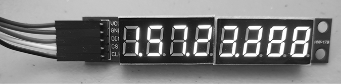
Figure 8-6: The stopwatch at work
Just as we did in Project 24, in this sketch we use millis() to track the elapsed time. We have put the time calculation and display in the function void displayResultLED() 1.
At 2, you can see how the elapsed time in milliseconds is broken down into hours, minutes, seconds, and milliseconds. Then, each digit of the display from left to right is filled with the corresponding time values, starting with hours 3. The stopwatch controls are simple: when the user presses the button connected to digital input 2, the counter is reset to zero by making the starting time equal to the current value returned by millis() 4. When the button connected to digital input 3 is pressed 5, the display is frozen; this functionality is ideal for taking a lap reading. Note, however, that the counting continues and the display resumes after about five seconds.
This project can easily be changed to display data in a simpler format—such as hours, minutes, and seconds—or to be used for longer periods, such as up to 24 hours. But for now, let’s move on to a more complex project involving LED matrix display boards.
Project #27: Using LED Matrix Modules
The MAX7219 can control up to 64 LEDs. These displayed numbers in the last project. Here, we’ll use modules that arrange the LEDs in an 8 × 8 matrix form that is ideal for more interesting applications, such as displaying fixed or scrolling text.
LED matrix modules are generally sold either as individual units or in sets of four; both are shown in Figure 8-7.
You may also see these advertised as kits; however, the cost savings is negligible, so save time with the preassembled versions. The LED displays fit onto the socketed pins on the module, as shown in Figure 8-8, allowing you to change colors easily.

Figure 8-7: LED matrix modules
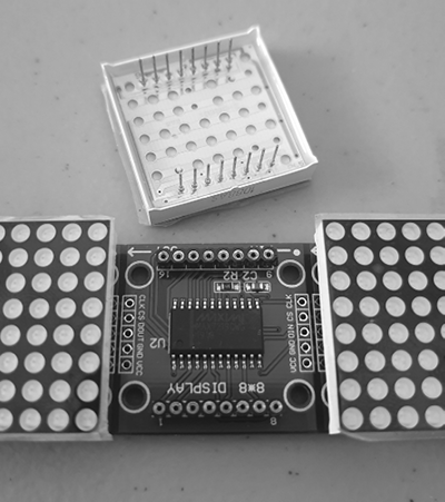
Figure 8-8: A removable LED matrix
Take care when inserting the LED matrix into the module, as some LED matrices have pins that get bent easily. Experience has shown that you still need to solder inline header pins to the matrix modules. However, these pins are generally included with the module and fit neatly, as shown in Figure 8-9.

Figure 8-9: Inline header pins connected to a matrix module
Once again, before you can use the matrix modules, you’ll need to connect five wires to both the module and the Arduino, just as you did with the numeric display. Make the connections as shown in Table 8-2.
Table 8-2: Connections Between the Matrix Module and Arduino
| Module pin label | Arduino pin | Module pin function |
| Vcc | 5V | Power (+) |
| GND | GND | Power (−) or ground |
| DIN | D11 | Data in |
| CS | D9 | Chip select |
| CLK | D13 | Clock signal |
Installing the Library
You’ll use a different library for these modules than for the MAX7219. To get the library, visit https://github.com/bartoszbielawski/LEDMatrixDriver/ and click Clone or Download, then Download ZIP, as shown in Figure 8-10.
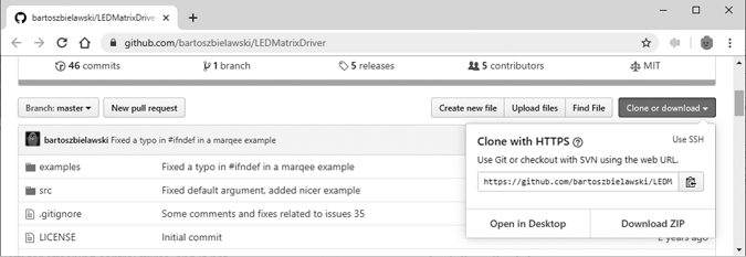
Figure 8-10: Downloading the LEDMatrixDriver library
After you have downloaded the ZIP file, install it as described in Chapter 7. Enter and upload the sketch that follows. (At this point, I’d like to remind you that all the code in this book can be downloaded from https://nostarch.com/arduino-workshop-2nd-edition/.)
// Project 27 - Using LED Matrix Modules
1 #include <LEDMatrixDriver.hpp>
const uint8_t LEDMATRIX_CS_PIN = 9;
// Number of matrix modules you are connecting
const int LEDMATRIX_SEGMENTS = 4;
const int LEDMATRIX_WIDTH = LEDMATRIX_SEGMENTS * 8;
LEDMatrixDriver lmd(LEDMATRIX_SEGMENTS, LEDMATRIX_CS_PIN);
// Text to display
2 char text[] = "** LED MATRIX DEMO! ** (1234567890) ++ "ABCDEFGHIJKLMNOPQRSTUVWXYZ" ++ <$%/=?'.@,> --";
// scroll speed (smaller = faster)
3 const int ANIM_DELAY = 30;
void setup() {
4 // init the display
  lmd.setEnabled(true);
  lmd.setIntensity(2);   // 0 = low, 10 = high
}
int x = 0, y = 0; // start top left
// font definition
5 byte font[95][8] = { {0, 0, 0, 0, 0, 0, 0, 0},      // SPACE
  {0x10, 0x18, 0x18, 0x18, 0x18, 0x00, 0x18, 0x18}, // EXCL
  {0x28, 0x28, 0x08, 0x00, 0x00, 0x00, 0x00, 0x00}, // QUOT
  {0x00, 0x0a, 0x7f, 0x14, 0x28, 0xfe, 0x50, 0x00}, // #
  {0x10, 0x38, 0x54, 0x70, 0x1c, 0x54, 0x38, 0x10}, // $
  {0x00, 0x60, 0x66, 0x08, 0x10, 0x66, 0x06, 0x00}, // %
  {0, 0, 0, 0, 0, 0, 0, 0},                         // &
  {0x00, 0x10, 0x18, 0x18, 0x08, 0x00, 0x00, 0x00}, // '
  {0x02, 0x04, 0x08, 0x08, 0x08, 0x08, 0x08, 0x04}, // (
  {0x40, 0x20, 0x10, 0x10, 0x10, 0x10, 0x10, 0x20}, // )
  {0x00, 0x10, 0x54, 0x38, 0x10, 0x38, 0x54, 0x10}, // *
  {0x00, 0x08, 0x08, 0x08, 0x7f, 0x08, 0x08, 0x08}, // +
  {0x00, 0x00, 0x00, 0x00, 0x00, 0x18, 0x18, 0x08}, // COMMA
  {0x00, 0x00, 0x00, 0x00, 0x7e, 0x00, 0x00, 0x00}, // -
  {0x00, 0x00, 0x00, 0x00, 0x00, 0x00, 0x06, 0x06}, // DOT
  {0x00, 0x04, 0x04, 0x08, 0x10, 0x20, 0x40, 0x40}, // /
  {0x00, 0x38, 0x44, 0x4c, 0x54, 0x64, 0x44, 0x38}, // 0
  {0x04, 0x0c, 0x14, 0x24, 0x04, 0x04, 0x04, 0x04}, // 1
  {0x00, 0x30, 0x48, 0x04, 0x04, 0x38, 0x40, 0x7c}, // 2
  {0x00, 0x38, 0x04, 0x04, 0x18, 0x04, 0x44, 0x38}, // 3
  {0x00, 0x04, 0x0c, 0x14, 0x24, 0x7e, 0x04, 0x04}, // 4
  {0x00, 0x7c, 0x40, 0x40, 0x78, 0x04, 0x04, 0x38}, // 5
  {0x00, 0x38, 0x40, 0x40, 0x78, 0x44, 0x44, 0x38}, // 6
  {0x00, 0x7c, 0x04, 0x04, 0x08, 0x08, 0x10, 0x10}, // 7
  {0x00, 0x3c, 0x44, 0x44, 0x38, 0x44, 0x44, 0x78}, // 8
  {0x00, 0x38, 0x44, 0x44, 0x3c, 0x04, 0x04, 0x78}, // 9
  {0x00, 0x18, 0x18, 0x00, 0x00, 0x18, 0x18, 0x00}, // :
  {0x00, 0x18, 0x18, 0x00, 0x00, 0x18, 0x18, 0x08}, // ;
  {0x00, 0x10, 0x20, 0x40, 0x80, 0x40, 0x20, 0x10}, // <
  {0x00, 0x00, 0x7e, 0x00, 0x00, 0xfc, 0x00, 0x00}, // =
  {0x00, 0x08, 0x04, 0x02, 0x01, 0x02, 0x04, 0x08}, // >
  {0x00, 0x38, 0x44, 0x04, 0x08, 0x10, 0x00, 0x10}, // ?
  {0x00, 0x30, 0x48, 0xba, 0xba, 0x84, 0x78, 0x00}, // @
  {0x00, 0x1c, 0x22, 0x42, 0x42, 0x7e, 0x42, 0x42}, // A
  {0x00, 0x78, 0x44, 0x44, 0x78, 0x44, 0x44, 0x7c}, // B
  {0x00, 0x3c, 0x44, 0x40, 0x40, 0x40, 0x44, 0x7c}, // C
  {0x00, 0x7c, 0x42, 0x42, 0x42, 0x42, 0x44, 0x78}, // D
  {0x00, 0x78, 0x40, 0x40, 0x70, 0x40, 0x40, 0x7c}, // E
  {0x00, 0x7c, 0x40, 0x40, 0x78, 0x40, 0x40, 0x40}, // F
  {0x00, 0x3c, 0x40, 0x40, 0x5c, 0x44, 0x44, 0x78}, // G
  {0x00, 0x42, 0x42, 0x42, 0x7e, 0x42, 0x42, 0x42}, // H
  {0x00, 0x7c, 0x10, 0x10, 0x10, 0x10, 0x10, 0x7e}, // I
  {0x00, 0x7e, 0x02, 0x02, 0x02, 0x02, 0x04, 0x38}, // J
  {0x00, 0x44, 0x48, 0x50, 0x60, 0x50, 0x48, 0x44}, // K
  {0x00, 0x40, 0x40, 0x40, 0x40, 0x40, 0x40, 0x7c}, // L
  {0x00, 0x82, 0xc6, 0xaa, 0x92, 0x82, 0x82, 0x82}, // M
  {0x00, 0x42, 0x42, 0x62, 0x52, 0x4a, 0x46, 0x42}, // N
  {0x00, 0x3c, 0x42, 0x42, 0x42, 0x42, 0x44, 0x38}, // O
  {0x00, 0x78, 0x44, 0x44, 0x48, 0x70, 0x40, 0x40}, // P
  {0x00, 0x3c, 0x42, 0x42, 0x52, 0x4a, 0x44, 0x3a}, // Q
  {0x00, 0x78, 0x44, 0x44, 0x78, 0x50, 0x48, 0x44}, // R
  {0x00, 0x38, 0x40, 0x40, 0x38, 0x04, 0x04, 0x78}, // S
  {0x00, 0x7e, 0x90, 0x10, 0x10, 0x10, 0x10, 0x10}, // T
  {0x00, 0x42, 0x42, 0x42, 0x42, 0x42, 0x42, 0x3e}, // U
  {0x00, 0x42, 0x42, 0x42, 0x42, 0x44, 0x28, 0x10}, // V
  {0x80, 0x82, 0x82, 0x92, 0x92, 0x92, 0x94, 0x78}, // W
  {0x00, 0x42, 0x42, 0x24, 0x18, 0x24, 0x42, 0x42}, // X
  {0x00, 0x44, 0x44, 0x28, 0x10, 0x10, 0x10, 0x10}, // Y
  {0x00, 0x7c, 0x04, 0x08, 0x7c, 0x20, 0x40, 0xfe}, // Z
};

6 void drawString(char* text, int len, int x, int y)
{
  for ( int idx = 0; idx < len; idx ++ )
  {
    int c = text[idx] - 32;

    // stop if char is outside visible area
    if ( x + idx * 8  > LEDMATRIX_WIDTH )
      return;

    // only draw if char is visible
    if ( 8 + x + idx * 8 > 0 )
      drawSprite( font[c], x + idx * 8, y, 8, 8 );
  }
}

7 void scrollText()
{
  int len = strlen(text);
  drawString(text, len, x, 0);
  lmd.display();

  delay(ANIM_DELAY);

  if ( --x < len * -8 ) {
    x = LEDMATRIX_WIDTH;
  }
}

void loop()
{
  scrollText();
}
A moment or two after the sketch has uploaded, you should see text scrolling from right to left across your LED display modules.
Now let’s dig in to see how this sketch works. There’s a lot of code, but don’t let that put you off. Starting at 1, we call the required functions to use the library and set up the displays. At 2, an array of characters contains the text to show on the display modules. You can change this later if you’d like. You can also adjust the speed of scrolling by altering the value at 3: the smaller the number, the faster the scroll speed.
At 4, we have two functions. This function turns the display on or off:
lmd.setEnabled(true);And this one sets the brightness of the LEDs in the display module:
lmd.setIntensity(x);The setIntensity() function takes values between 0 (dim) and 9 (bright).
The font used by the display is defined in the huge array at 5. We’ll return to that in the next section. Finally, the functions drawstring() 6 and scrollText() 7 are required for display operation.
Editing the Display Font
You can easily specify which characters are usable in the display by changing the data in the byte font array 5. First, recall that each matrix module is made up of eight rows of eight LEDs. This means you have 64 LEDs available for any character you create.
Each row of LEDs is defined by a hexadecimal number, and eight of these hexadecimal numbers represent a character. For example, the letter N is defined by:
{0x00, 0x42, 0x42, 0x62, 0x52, 0x4a, 0x46, 0x42}, // NTo visualize the character, we convert the hexadecimal numbers to binary. For example, our letter N converted from hexadecimal to binary is:
0 0 0 0 0 0 0 0 = 0x00
0 1 0 0 0 0 1 0 = 0x42
0 1 0 0 0 0 1 0 = 0x42
0 1 1 0 0 0 1 0 = 0x62
0 1 0 1 0 0 1 0 = 0x52
0 1 0 0 1 0 1 0 = 0x4a
0 1 0 0 0 1 1 0 = 0x46
0 1 0 0 0 0 1 0 = 0x42
You can see how the 1s represent the character against a field of 0s, with the 1s being LEDs turned on and the 0s being LEDs turned off. So, to create your own characters, just reverse the process. For example, a nice smiley face can be represented as:
0 1 1 1 1 1 1 0 = 0x7e
1 0 0 0 0 0 0 1 = 0x81
1 0 1 0 0 1 0 1 = 0xa5
1 0 0 0 0 0 0 1 = 0x81
1 0 1 0 0 1 0 1 = 0xa5
1 0 0 1 1 0 0 1 = 0x99
1 0 0 0 0 0 0 1 = 0x81
0 1 1 1 1 1 1 0 = 0x7e
This would be represented in the array as:
{0x7e,0x81,0xa5,0x81,0xa5,0x99,0x81,0x7e} // smileyYou can either replace an existing line in the font array with your new data or add your data to the end of the array as another element. If you add another line, you need to increase the first parameter in the byte declaration so that the first parameter equals the number of defined characters (in this case, 96):
byte font[96][8]You’re probably wondering by now how to refer to your custom character in the sketch. The display library uses the character order in the ASCII chart, which can be found at https://www.arduino.cc/en/Reference/ASCIIchart/.
If you add another character after the last one in the sketch (which is Z by default), the next character in the table is [. Thus, to scroll three smiley faces across the display, you would set the line with text to display to:
char text[] = "[ [ [ ";An example of this output can be seen in Figure 8-11.

Figure 8-11: Using custom characters to display smiley faces
Looking Ahead
Now that you know how to use them, working with LED numeric and matrix displays will be a cinch. However, there are more types of displays, so turn to the next chapter to learn about another one: liquid crystal displays.