Chapter 6
Controlling Object Visibility and Appearance
Layers control objects whether they are visible or hidden. All objects have properties that control their appearance—properties such as color, linetype, lineweight, and so on. The layers to which objects are assigned usually control general object properties, but these properties can be set on a per-object basis as well. This chapter explores the many AutoCAD® tools associated with layers that illustrate the importance of layers in managing the complexity of design.
- Changing object properties
- Setting the current layer
- Altering the layer assignments of objects
- Controlling layer visibility
- Applying linetype
- Assigning properties by object or by layer
- Managing layer properties
Changing Object Properties
All objects have properties controlling their appearance. When you draw a line, you are ultimately specifying its geometric properties (the start point and the endpoint). Likewise, when you draw a circle, you are just specifying its center point and radius properties. Geometric properties are the most important factor governing how objects look and in determining where the objects are in space.
In addition to geometric properties, all objects share a short list of general properties: layer, color, linetype, linetype scale, lineweight, transparency, and thickness. Although general properties are assigned on a per-object basis, they are usually controlled by using layers.
Let’s explore object properties in an existing drawing and then learn how to change properties and merge the layers to which objects are assigned:
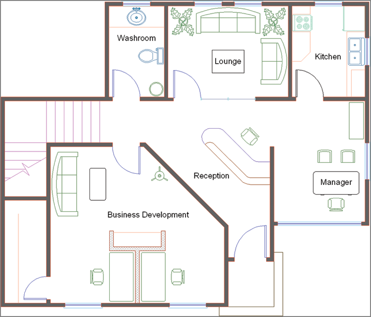
2. Zoom into the reception desk at the center of the small office plan.
3. Toggle on the Quick Properties mode in the status bar.
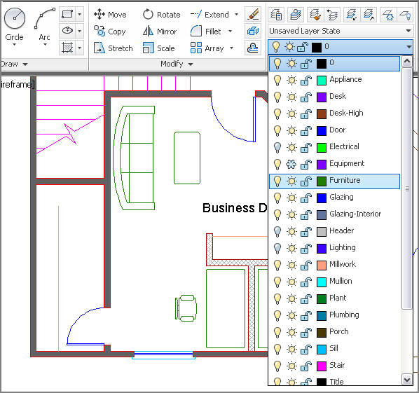
4. Click on the line of the desk immediately adjacent to the Reception text object; the Quick Properties panel appears at the top right of the selected object on the drawing canvas. Click the Desk-High layer name to activate the Layer drop-down menu (see
Figure 6-2).
You can change the properties of multiple objects simultaneously by selecting more than one object in Quick Properties mode. However, only the properties that the selected items have in common are displayed.
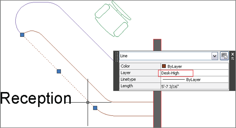
5. Select the Desk layer in the drop-down (see
Figure 6-3), and press the Esc key to exit Quick Properties mode. Observe that the line whose layer property you changed now appears violet, like the other objects on the Desk layer.
6. Expand the Layers panel on the Home tab of the ribbon.
7. Click the Merge tool. The command prompt reads:
Select object on layer to merge or [Name]:
8. Click one of the brown lines in the upper portion of the reception desk and press Enter.
9. Click the violet line you changed to the Desk layer in step 5 and press Enter. The command prompt reads:
Select object on target layer or [Name]:
******** WARNING ********
You are about to merge layer "Desk-High" into layer "Desk".
Do you wish to continue? [Yes/No] <No>:
10. Press Y (for Yes), and then press Enter to continue. The Desk-High layer is deleted, and the objects that were on it have been reassigned to the Desk layer. The LAYMRG command is done.
Use the
LAYDEL command to delete a layer and everything on it. Be careful, though, to avoid deleting valuable information.
11. Expand the Properties panel, and click the List tool. Pan over and select the Business Development text object by clicking on it and pressing Enter. The AutoCAD Text window appears, displaying the following property information:
TEXT      Layer: "Title"
Space: Model space
Handle = 71e
Style = "Standard"
Annotative: No
Typeface = Arial
mid point, X= 193.8805  Y= 132.8080  Z= 0.0000
height    7.5000
text Business Development
rotation angle      0
width scale factor    1.0000
obliquing angle      0
generation normal
This list might be helpful if you were looking for a particular piece of information, but you can’t edit any of the properties directly. Close the AutoCAD Text window.


12. Select the View tab on the ribbon and, under Panels, click the Properties tool to open the Properties panel.
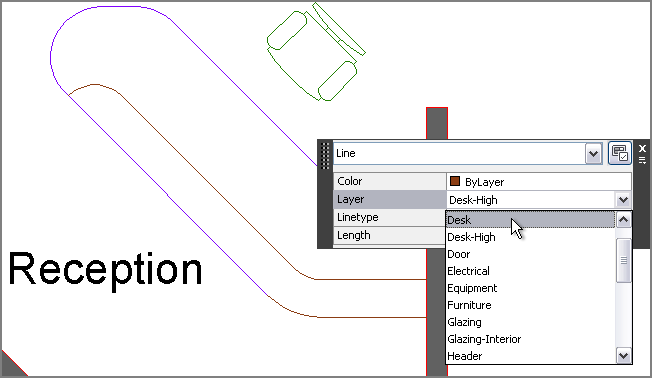
13. Select the Business Development text object you selected in step 11. Many of its properties appear in the panel (see
Figure 6-4). Property values displayed on a white background are editable; those on a gray background are for your information only.
Although the
LIST command shows some property information that does not appear in the Properties panel, most people prefer using the panel because much of the data is directly editable.
14. Select the words “Business Development” in the Contents property, type Marketing, and press Enter. Press Esc to deselect the text object. The department’s name has been changed. You can now close the Properties panel.
Setting the Current Layer
Objects are always drawn on the current layer, and there is only one current layer at any given time. Every drawing has at least one layer, layer 0 (zero), which is current by default when you create a new drawing.
AutoCAD has another special layer called Defpoints, which is automatically created when you add associative dimensions to a drawing (see Chapter 11, “Dimensioning”).
You cannot delete or rename layer 0 or Defpoints. It’s okay to draw on layer 0, but not on Defpoints.
Let’s experiment with setting the current layer by drawing a few objects:
1. Using the Ch6-A.dwg (or Ch6-A-metric.dwg) file, zoom into the Manager’s office. If this file is not open, find it on the book’s web page.
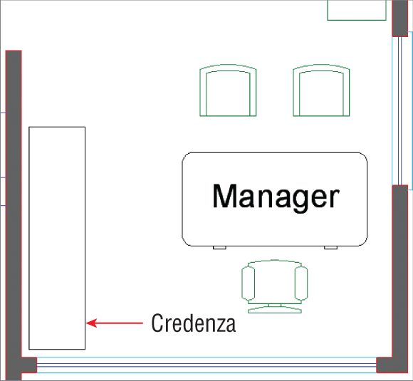
2. Click the Rectangle tool on the Draw panel, and click a point a few inches (no need to measure) from the lower-left corner of the room. Type
@18,72 (or
@45,180 for metric) and press Enter to create a credenza in the Manager’s office (see
Figure 6-5).
Press Shift, right-click, and choose the None object snap to override any running object snap modes whenever necessary.
3. Select the rectangle you drew in the previous step, and change its Layer assignment to Furniture in the Quick Properties window that appears. Press Esc to deselect.
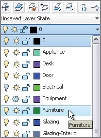
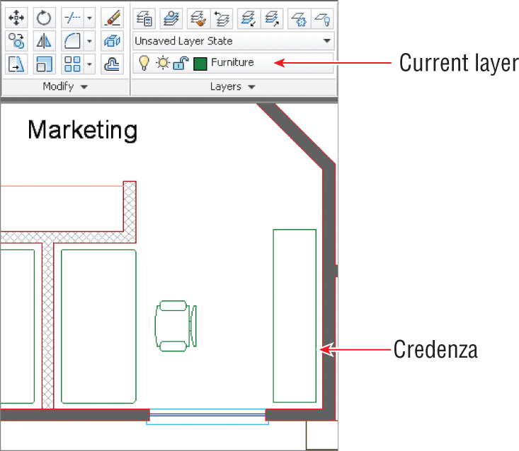
4. If you plan on drawing more than one object, a more efficient approach is to set the current layer prior to drawing, so that the new object will have the proper layer assignment automatically. Open the Layer drop-down menu in the Layers panel, and click on or to the right of the word Furniture to set this layer as current. Notice that Furniture appears “on top” when the drop-down is closed (see
Figure 6-6); Furniture is now the current layer.
5. Pan over to the Marketing space.
6. Click the Rectangle tool on the Draw panel, and click a point a few inches (without measuring) from the lower-right corner of the room. Type
@-18,72 (or
@-45,180 for metric), and press Enter to create a credenza in Marketing (see
Figure 6-7).
7. Select the rectangle you drew in the previous step, and verify that it is on the Furniture layer in the Quick Properties window that appears. Press Esc.
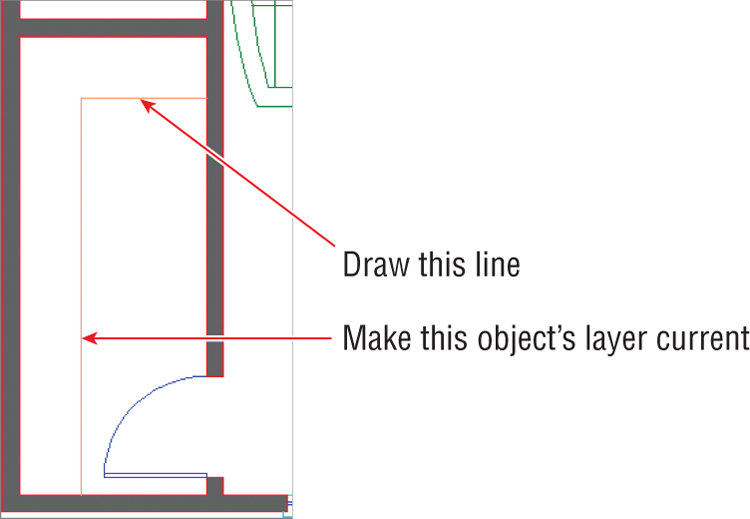
8. Pan over to the closet in Marketing. One of the lines representing shelves is missing. You will draw the missing line on the same layer as the existing shelf line.
9. Rather than selecting the existing shelf line by learning its layer name and then setting that layer as current, there is a more efficient approach. In the Layers panel, click the Make Object’s Layer Current tool. Click the existing shelf line in Marketing’s closet. The layer appearing at the top of the Layer drop-down menu is Millwork, which shows that it’s now the current layer.
10. Toggle on Endpoint and Perpendicular running object snap modes on the status bar.
11. Click the Line tool on the Draw panel, and draw the line shown in
Figure 6-8. Press Esc to end the
LINE command.
Altering the Layer Assignments of Objects
Although you have already changed the layer assignments of objects using Quick Properties, there are more efficient methods of doing so, some of which do not require you to remember a layer name. Let’s explore several methods for changing the layer assignments of existing objects:
1. Using the Ch6-A.dwg (or Ch6-A-metric.dwg) file, zoom into the Marketing office. If this file is not open, find it on the book’s web page.
2. Toggle off Quick Properties mode on the status bar.
3. Select the coffee table. Notice that the entry in the Layer drop-down in the Layers panel changes to layer 0; this does not mean that layer 0 is current (Millwork is), only that the selected item is on layer 0.
A preview of property changes appears on screen as you hover over items in the Layers drop-down menu or the Properties panel.
4. Open the Layer drop-down menu, and click Furniture (see
Figure 6-9) to change the layer assignment of the selected items. Press Esc to deselect.
5. Pan over to the Lounge.
6. Click the Match tool in the Layers panel, select the coffee table in the Lounge, and press Enter. The command prompt reads:
Select object on destination layer or [Name]:
7. Click one of the sofas in the Lounge and press Enter; the LAYMCH command ends. The coffee table is now assigned to the same layer as the sofas (Furniture).
8. Pan to the Manager’s office.
9. Click the Match Properties tool in the Clipboard panel on the Home tab of the ribbon. Select the credenza in the Manager’s office and press Enter. The command prompt reads:
Select destination object(s) or [Settings]:
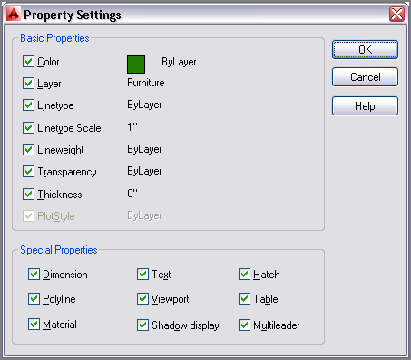
10. Type
S (for Settings), and press Enter; the Property Settings dialog box appears. You can match many properties in addition to layers with this tool (see
Figure 6-10). Click OK.
11. Click the desk in the Manager’s office and press Enter; the desk turns green because it is now on the Furniture layer. Press Esc to exit the MATCHPROP command.
Merging Layers
In AutoCAD 2014, you can merge the contents of multiple layers into a single layer. First, select the layers you wish to merge in the Layer Properties Manager (using the Ctrl key to select multiple nonsequential layers), right-click, and select Merge Selected Layers To. You are then presented with a dialog box where you can select the single destination layer from a list. The source layers are automatically purged after their contents are merged into the destination layer.
Controlling Layer Visibility
In traditional drafting, separate drawings would have to be made for the floor plan and the reflected ceiling plan to represent the floor and ceiling of the same space. In AutoCAD, simply displaying some layers while hiding others allows you to create some of the drawings required to describe the space graphically.
To understand better how to do this, you need to learn how to toggle layer status, isolate layers to work without distraction, and save layer states to recall the layer status of multiple layers quickly.
Toggling Layer Status
In addition to having properties such as color, linetype, lineweight, and so on, layers have states that can be toggled, including On/Off, Thaw/Freeze, and Lock/Unlock. As you’ll see in the following steps, layer states control the visibility and editability of the objects assigned to layers:
1. Using the Ch6-A.dwg (or Ch6-A-metric.dwg) file, zoom out to show the entire office. If this file is not open, find it on the book’s web page.
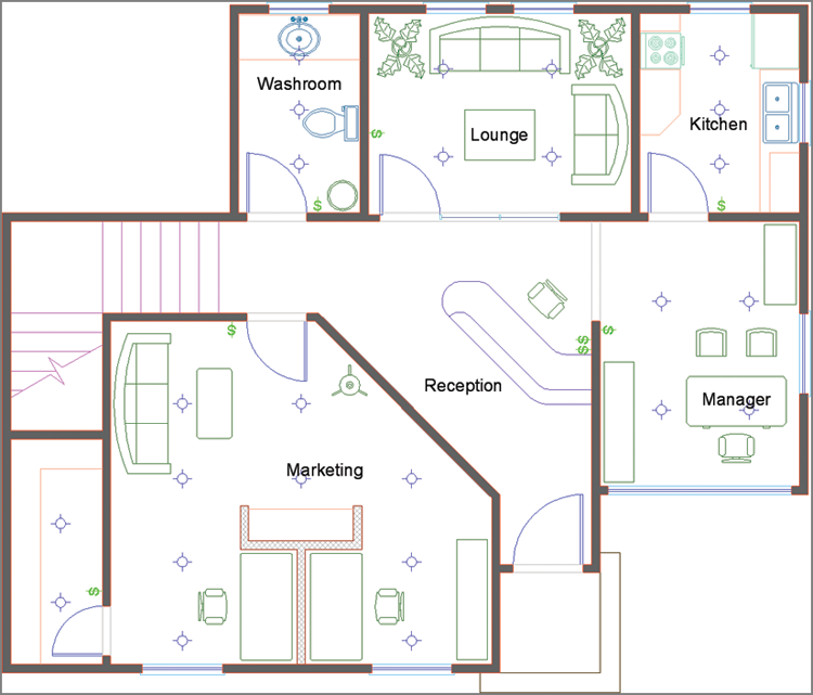
2. Expand the Layers panel, and click the Turn All Layers On tool. You now see the switches ($ symbols), downlights, and header layers.
Figure 6-11 shows the result.
3. Open the Layer drop-down menu in the Layers panel, and click the Appliance layer’s lightbulb icon to toggle it off. Toggle off the Desk layer as well. Click outside the Layer drop-down menu to close it.
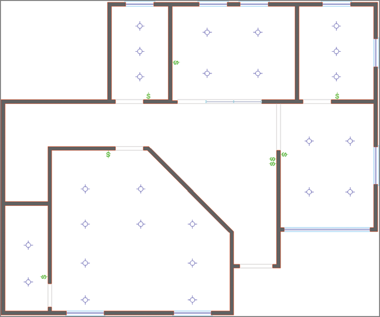
4. Another approach to turning layers off doesn’t require that you know layer names. Click the Off tool in the Layers panel, and click the following objects: sink, door, chair, plant, stairs, low wall, low wall’s pattern fill, text, and the porch. Click a kitchen cabinet and the command prompt reads:
Layer "Millwork" is current, do you want to
turn it off? [Yes/No] <No>:
If you turn the current layer off, then anything you draw subsequently will be hidden.
5. Type
Y (for Yes), and press Enter. Press Esc to end the
LAYOFF command.
Figure 6-12 shows the result.
6. Open the Layer drop-down menu in the Layers panel, and set layer 0 as current.
7. Click Zoom Extents in the Navigation bar. Notice that there is a gap between the bottom wall of the building and the lower edge of the drawing canvas. Even though it is off, the Porch layer is still defining the extents of the drawing.
8. Open the Layer drop-down menu in the Layers panel, and freeze the Porch layer. Press Esc to close the drop-down menu.
9. Click Zoom Extents in the Navigation bar again. The gap disappears because the Porch layer is no longer calculated when it is frozen and therefore is no longer part of the drawing extents.
10. Expand the Layers panel, and click the Lock tool. Select one of the lights. The Lighting layer is now locked.
Locking layers doesn’t provide security other than disallowing selection.
11. Type
E (for Erase), and press Enter. Click on a different light, and observe a tiny padlock appear near the object (see
Figure 6-13). You can’t select the object because it is locked. In order to see the padlock, you must select When A Command Is Active in the Selection Preview area on the Selection tab in the Options dialog box (
OPTIONS command).
Isolating Layers
You can quickly isolate one or more layers to work on them without the visual clutter of all the other layers. Let’s try out Isolation mode:
1. Use the Ch6-A.dwg (or Ch6-A-metric.dwg) file. If this file is not open, find it on the book’s web page.
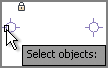
2. Click the Isolate tool on the Layers panel, and then make a crossing selection through one of the windows. Press Enter and all the other layers disappear (see
Figure 6-14).
3. Expand the Layers panel, and click the Copy Objects To New Layer tool. Select each one of the nine sill lines on the inside of the building and press Enter. The command prompt reads:
Select object on destination layer or [Name] <Name>:
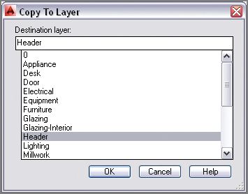
4. Type
N (for Name), and press Enter. The Copy To Layer dialog box appears (see
Figure 6-15). Select Header from the Destination Layer list, click OK, and press Enter. There are now nine lines on the Sill layer and nine duplicate lines on the Header layer.
5. Click the Unisolate tool on the Layers panel. The layers return to the way they were before you used the Isolate tool.
6. Type LAYOFF, and press Enter. Click one of the sills on the outside of the building to turn off the Sill layer and press Enter. Open the Layer drop-down menu, and toggle on the Header layer.
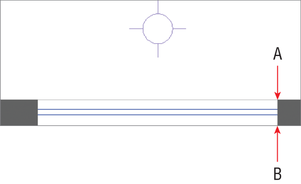
7. Zoom into one of the lower windows, and click the Distance tool in the Utilities panel. Click points A and B shown in
Figure 6-16 to measure the wall thickness. The command prompt reads:
Distance = 5.0000, Angle in XY Plane = 270,
Angle from XY Plane = 0
Delta X = 0.0000, Delta Y = -5.0000, Delta Z = 0.0000
8. Press Esc to cancel the DISTANCE command.
9. Type O (for Offset), press Enter, type 5 (or 12.7 for metric), and press Enter again. Click the header line in the window opening, and then click below it to offset a line on the outer edge of the wall.
10. Continue clicking each header and a point outside the building to offset a second header line in each window opening. Press Enter to end the OFFSET command when done. The reflected ceiling plan is complete.
Saving Layer States
In this section, you will learn how to save collections of layer states for later recall. You have already created a reflected ceiling plan in this chapter, and you will now save it as a layer state so that you won’t have to repeat all the work of toggling layer states in the future.
1. Use the Ch6-A.dwg (or Ch6-A-metric.dwg) file. If this file is not open, find it on the book’s web page.
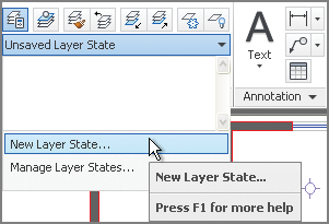
2. Open the drop-down menu directly above the Layer drop-down (it says Unsaved Layer State by default). Select New Layer State in the drop-down menu (see
Figure 6-17).
3. Type Reflected Ceiling Plan in the New Layer State To Save dialog box and click OK. The closed drop-down now says Reflected Ceiling Plan.
4. Expand the Layers panel, and click the Turn All Layers On tool.
5. Expand the Layers panel again, and click the adjacent Thaw All Layers tool.
Using
LAYERP (Layer Previous) undoes the last set of changes to layers. This is different from
UNDO, which affects more than layers.
6. Click the Freeze tool in the Layers panel, and select the following objects: light, switch, header, and computer. The layers Lighting, Electrical, Header, and Equipment are frozen. Press Enter to end the LAYFRZ command.
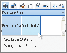
7. Open the Layer State drop-down menu in the Layers panel, and click New Layer State. Type Furniture Plan in the New Layer State To Save dialog box and click OK.
8. Open the Layer State drop-down menu, and select Reflected Ceiling Plan (see
Figure 6-18). All the layer states associated with the Reflected Ceiling Plan are immediately toggled. Switch back to the Furniture Plan state, and you’ll see the value in saving layer states (it saves lots of time).
Applying Linetype
In traditional drafting, you draw short, interrupted line segments when you want to indicate what is called a hidden line. Hidden lines represent objects that are above the section plane. For example, objects such as upper cabinets, high shelves, or a roof edge are shown as hidden because they are above an imaginary section line cutting the building horizontally.
In AutoCAD, lines are not interrupted (broken into multiple little pieces) to indicate hidden lines. Instead, continuous lines are assigned a linetype, and this style makes lines appear as if they are interrupted. One advantage to this is that you can adjust the scale of the line breaks without having to redraw myriad little lines. Let’s explore linetype and linetype scale:
1. Using the Ch6-A.dwg (or Ch6-A-metric.dwg) file, zoom out to view the entire office. If this file is not open, find it on the book’s web page.
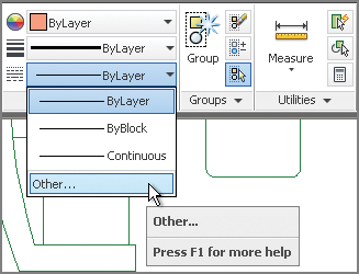
2. Open the Linetype drop-down menu in the Properties panel, and select Other at the bottom of the menu (see
Figure 6-19).
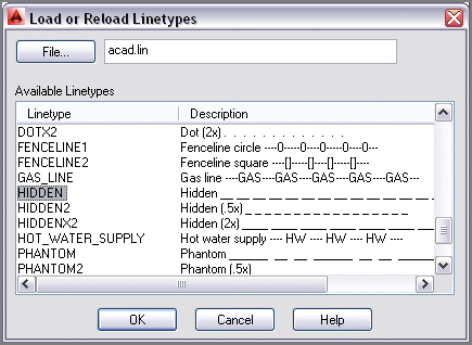
3. In the Linetype Manager dialog box that appears, click the Load button. Scroll down in the Load Or Reload Linetypes dialog box that appears, and select Hidden in the list (see
Figure 6-20); then click OK. Hidden now appears in the Linetype Manager dialog box because this particular linetype style has been loaded in the drawing file; click OK to close the Linetype Manager dialog box.
4. Zoom into the closet in the Marketing space, and select both lines on the Millwork layer, representing a high shelf.
5. Open the Linetype drop-down menu in the Properties panel, and select Hidden from the menu. Now the two selected lines have the Hidden linetype assigned.
6. You still don’t see breaks in the lines because the linetype scale is too small by default. Type
LTSCALE (for Linetype Scale), and press Enter. The command prompt reads:
LTSCALE Enter new linetype scale factor <1.0000>:
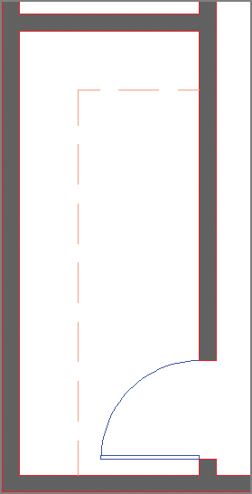
7. Type
48 (or
50 for metric), and press Enter. The lines appear with breaks indicating that the shelf is above the section plane (see
Figure 6-21).
The factor 50 is appropriate for 1:50 metric drawings.
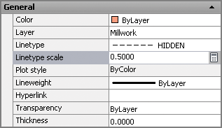
8. Select the horizontal shelf line, right-click, and choose Properties from the context menu.
9. Change Linetype Scale to
0.5 in the General section of the Properties panel (see
Figure 6-22).
Use
LTSCALE to set the linetype scale affecting the entire drawing. Higher values of
LTSCALE scale linetypes smaller.
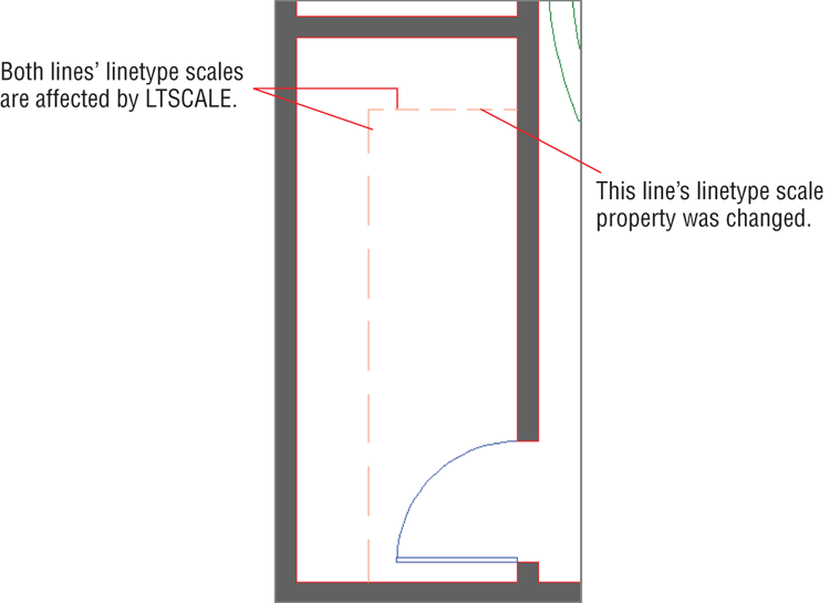
10. Press Esc to deselect the horizontal shelf line. The breaks in the horizontal line are half as large as those in the vertical segment (see
Figure 6-23). Close the Properties panel.
Alter the linetype scale of specific objects by adjusting the Linetype Scale property in the Properties panel. Lower values scale linetypes smaller.
Assigning Properties by Object or by Layer
Properties such as color, linetype, and lineweight are typically assigned by layer rather than by object. There is a special property value called ByLayer that passes control over specific properties to the properties managed by the layer to which the objects are assigned. As you’ll see in these steps, using the ByLayer property is a lot easier than it sounds:
1. Using the Ch6-A.dwg (or Ch6-A-metric.dwg) file. If this file is not open, find it on the book’s web page.
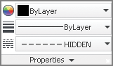
2. Open the Linetype drop-down menu on the Properties panel, and select Hidden (see
Figure 6-24). Draw a line of arbitrary length anywhere on the canvas.
3. Open the Linetype drop-down menu on the Properties panel, and select ByLayer.
4. Draw another line, and observe that it has continuous linetype.
Objects should be assigned specific colors, linetypes, or lineweights only in exceptional circumstances.
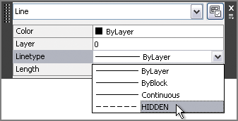
5. If you want to change the property of a specific object, use Quick Properties instead of the drop-down menus in the Properties panel. Toggle on Quick Properties mode on the status bar.
6. Select the continuous line drawn in step 2, and change its Linetype property to Hidden (see
Figure 6-25).
7. Draw another line, and verify that it has continuous linetype.
8. Delete all three arbitrary lines you’ve just drawn.
Managing Layer Properties
The Layer Properties Manager is where you create layers and manage the properties that are assigned to them. Let’s explore the Layer Properties Manager with a practical example:
1. Use the Ch6-A.dwg (or Ch6-A-metric.dwg) file. If this file is not open, find it on the book’s web page.
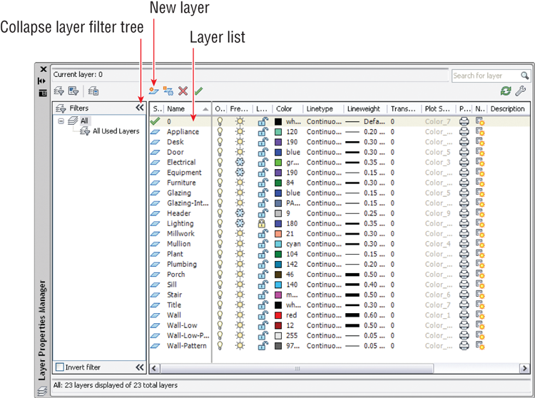
2. Click the Layer Properties tool in the Layers panel. The Layer Properties Manager appears (see
Figure 6-26).
3. Click Collapse The Layer Filter Tree to save some space in the panel.
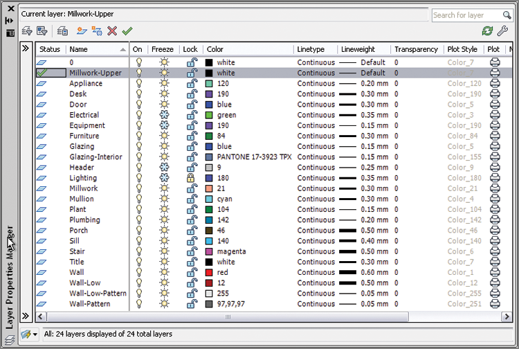
4. Click the New Layer button, type Millwork-Upper as the new layer’s name, and press Enter.
5. Double-click the blue parallelogram next to the new layer to set it as current. Now there is a green check mark next to the Millwork-Upper layer.
6. Right-click any one of the column headers to access a context menu. Choose Maximize All Columns from this menu.
Figure 6-27 shows the result: The columns are all readable.
Sorting columns is a quick way to find layers that have common properties. Drag the vertical bars between columns to resize them.
7. Click the Freeze column header to sort the column by that criterion (frozen state). Click the Freeze column header again to reverse the sort order. All columns are sortable.
8. Click the word Continuous in the Linetype column in the Millwork-Upper layer. In the Select Linetype dialog box that appears, choose Hidden and click OK.
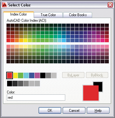
9. Click Millwork-Upper’s color swatch to open the Select Color dialog box. Click the larger red swatch where indicated (see
Figure 6-28) and click OK.
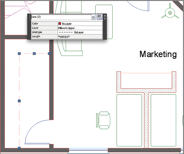
10. Zoom into the closet in the Marketing space, and select both shelf lines. Change Layer to Millwork-Upper and Linetype to ByLayer in the Quick Properties window (see
Figure 6-29). The two lines appear red with Hidden linetype. Close the Layer Properties Manager.
11. Your drawing should now resemble Ch6-B.dwg (or Ch6-B-metric.dwg), which is available among the book’s download files.
The Essentials and Beyond
In this chapter, you learned how to control object visibility and how to modify object appearance with layers and properties. You learned many ways to change object properties, set the current layer, alter the layer assignments of objects, control layer visibility, apply linetypes, use the ByLayer property, and manage properties with layers. You now have a greater ability to manage design complexity.
Additional Exercise
Explore layer property and group filters on your own by opening one of the sample files that ships with AutoCAD, such as:
C:Program FilesAutodeskAutoCAD 2014Sample
Sheet SetsArchitecturalA-01.dwg
Layer filters are especially useful in complex drawings where you need to manage dozens, or even hundreds, of layers.