Chapter 7
Organizing Objects
The fundamental entities in the AutoCAD® program are lines, polylines, circles, arcs, ellipses, and text. By combining these entities into blocks and/or groups, you can manipulate more complex objects, such as chairs, mechanical assemblies, trees, or any other organizational designation appropriate to your industry.
Manipulating blocks is an efficient means of working not only because it reduces the number of items requiring selection, but also because blocks can potentially control numerous references from a single definition. In this chapter, you will learn how groups are a flexible means of organizing collections of objects, which often include blocks as members. You will also learn how to select and manipulate a group as a whole, or access the members of the group individually whenever needed.
- Defining blocks
- Inserting blocks
- Editing blocks
- Redefining blocks
- Working with groups
Defining Blocks
Before drawing and copying a series of repetitive elements, you should first define them as a block. This is because you have a higher level of organizational control over blocks than you do over individual entities. In this section, you will draw a chair and a door and then define them as blocks.
Drawing a Chair and Defining It as a Block
In the following steps, you will use the drawing skills that you’ve learned in previous chapters to draw a chair. Then you will convert the chair into a block definition.
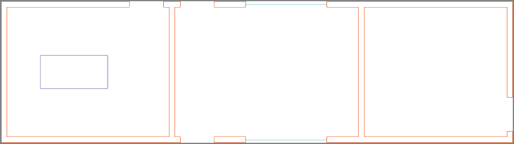
2. Zoom into the leftmost room above the desk.
3. Click the Rectangle tool on the Modify panel, and then click an arbitrary point above the desk (which is represented by the blue rectangle) as the first corner point. The command prompt reads:
Specify other corner point or [Area Dimensions Rotation]:
Type @18,18 (or @45,45 for metric), and press Enter.
4. Click the Explode tool on the Modify panel, select the rectangle you just drew, and press Enter. The single polyline is converted into four independent line objects.
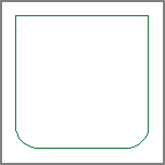
5. Click the Fillet tool on the Modify panel, type R (for Radius), and press Enter. Type 3″ (or 7 cm for metric), and press Enter to set the fillet radius; then click the left and bottom edges to create an arc.
6. Press the spacebar to repeat the
FILLET command. Click the bottom and right edges to create another arc.
Figure 7-2 shows the result.
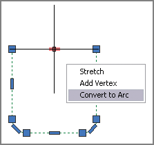
7. Expand the Modify panel, click the Join tool, select all the objects making up the chair you are drawing, and press Enter. Four lines and two arcs have now been converted into a single polyline.
8. Toggle on Ortho mode on the status bar.
9. Select the polyline you joined in step 7. Hover the cursor over the top-middle grip, and select Convert To Arc from the multifunction grip menu that appears (see
Figure 7-3).
10. Move the cursor upward, type 3″ (or 7 cm), press Enter, and then press Esc to clear the selection. You’ve created the curve of the backrest.
11. Click the Explode tool on the Modify panel, press Enter, select the chair, and press Enter again. The polyline is converted into three lines and three arcs.
12. Click the Offset tool in the Modify panel, type 2″ (or 5 cm for metric), and press Enter. Select the arc you created in step 9 and then click a point above it on the drawing canvas to offset a new arc 2″ (or 5 cm) above. Press Enter to exit the OFFSET command.
13. Type BLEND, press Enter, and select the two arcs making up the backrest near their left endpoints. A spline object smoothly joins the arcs.
14. Press Enter to repeat the
BLEND command, and select the two arcs near the right endpoints; another spline object is created (see
Figure 7-4).
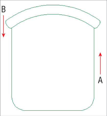
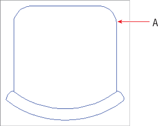
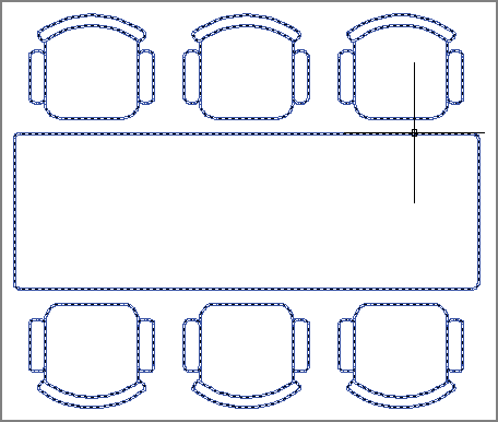
15. Click the Stretch tool in the Modify panel, click points A and B shown in
Figure 7-4 to create a crossing window, and press Enter. Click an arbitrary point on the drawing canvas as the first point of the Stretch operation. Move the cursor downward on the drawing canvas, type
3″ (or
7 cm for metric), and press Enter. The seat depth is reduced.
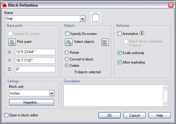
16. Select the entire chair with an implied window. Click the Create tool in the Block panel on the ribbon’s Home tab, and the Block Definition dialog box appears. Type Chair in the Name field. Every block must have a name.
A preview image of the chair appears to the right of the Name field because you selected its constituent objects prior to opening the Block Definition dialog box.
17. Every block has a
base point, which should be related to its geometry. Click the Pick Point button in the Base Point section; the Block Definition dialog box disappears. Hold Shift, and right-click to open the context menu; select Midpoint. Click the midpoint of the chair’s front edge. The Block Definition dialog box reappears, showing the coordinates of the point to which you snapped (see
Figure 7-5).
18. Choose the Delete radio button in the Objects section of the Block Definition dialog box. Select Scale Uniformly and Allow Exploding. Deselect Annotative and Open In Block Editor. Set the Block Unit drop-down to Inches (or Centimeters) and click OK. The chair disappears; don’t worry, you will insert it later.
Understanding the Block Table
When the chair disappeared from the drawing canvas, it was defined in the drawing’s block table. Although every drawing has a block table, you can’t see it. Blocks defined there can be inserted into the drawing as block references. Changes made to block definitions (stored in the block table) affect all block references in the drawing.
Drawing a Door and Defining It as a Block
In the following steps, you will draw a door and the representation of its swing (an arc) and define it as a block:
1. If the file Ch7-A.dwg (or Ch7-A-metric.dwg) is not already open, go to the book’s web page, browse to Chapter 7, and open the file.
2. Pan over to the middle room. Zoom into the door opening along the bottom edge of this room.
3. Toggle on Running Object Snap mode on the status bar. Right-click this button, and turn on Endpoint snap if it’s not already highlighted in the context menu.
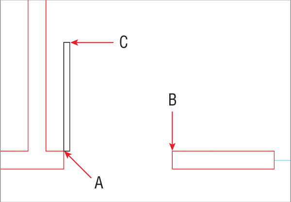
4. Click the Rectangle tool in the Draw panel. Snap the first corner at point A, as shown in
Figure 7-6. Type
@1.5,2′6″ (or
@4,75 for metric), and press Enter to complete the door.
All door openings in the sample file measure 2′6″ (75 cm) in width.
5. Click to open the Arc pull-down menu on the Draw panel, and select the Center, Start, End tool. Click points A, B, and C as shown in
Figure 7-6 to create the swing.
6. Type B (for Block), and press Enter. The Block Definition dialog box appears.
7. Type Door in the Name field, and click the Select Objects button. Select the rectangle and the arc and press Enter. Select the Pick Point button, click the door hinge, and press Enter. Select the Convert To Block radio button and click OK.
The Convert To Block option both creates a block definition and inserts it into the drawing as a block reference.
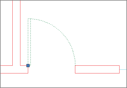
8. Select the door, and observe that it has only one grip because it is now a block reference (see
Figure 7-7). Press Esc to deselect.
9. Save your work as Ch7-B.dwg (or Ch7-B-metric.dwg).
Inserting Blocks
After you create a block definition, you can insert local block references (from the current drawing’s block table) into the drawing. In Chapter 9, “Working with Blocks and Xrefs,” you will learn how to create and insert global blocks, which are blocks that exist outside the current drawing file. In this section, however, you will simply focus on inserting the local chair and door blocks that you defined in the previous section.
1. If the file is not already open, go to the book’s web page, browse to Chapter 7, get the file Ch7-B.dwg (or Ch7-A-metric.dwg), and open it.
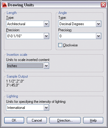
2. Type
UN (for Units), and press Enter. Open the Insertion Scale drop-down menu, and select Inches (or Centimeters) if it is not already selected (see
Figure 7-8). Click OK to close the Drawing Units dialog box.
The units you use in the Block Definition dialog box should match the Insertion Scale units; otherwise, AutoCAD will scale blocks when you insert them into the drawing.
3. Zoom into the room with the table on the left. Verify that Dynamic Input is off.
4. Right-click the object snap toggle on the status bar, and turn on Midpoint snap if it’s not already highlighted in the context menu.
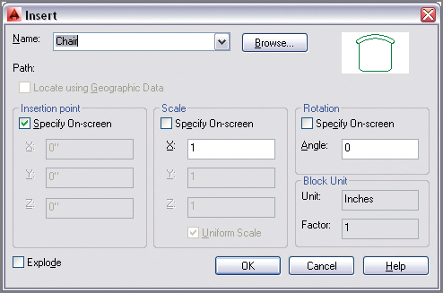
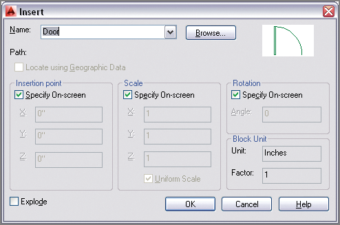
5. Click the Insert tool on the Block panel on the ribbon’s Home tab. Open the Name drop-down list in the Insert dialog box and select Chair. If it’s not already selected, choose Specify On-Screen in the Insertion Point section of the Insert dialog box (see
Figure 7-9). Click OK.
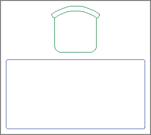
6. Hold Shift, right-click, and choose From in the context menu. Click the midpoint of the upper desk edge, type
@0,3 (or
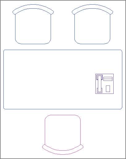
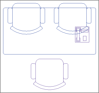
@0,7 for metric), and press Enter. The Chair block reference appears 3″ (or 7 cm) up from the center of the desk (see
Figure 7-10).
7. Click the Move tool in the Modify panel, select the Chair block, and press Enter. Click an arbitrary point on the drawing canvas, type @1′3″<180 (or @40<180 for metric), and press Enter to move the chair to the left.
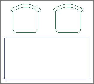
8. Click the Copy tool in the Modify panel, type
L (for Last), and press Enter twice. Click an arbitrary point on the drawing canvas, type
@2′6″<0 (or
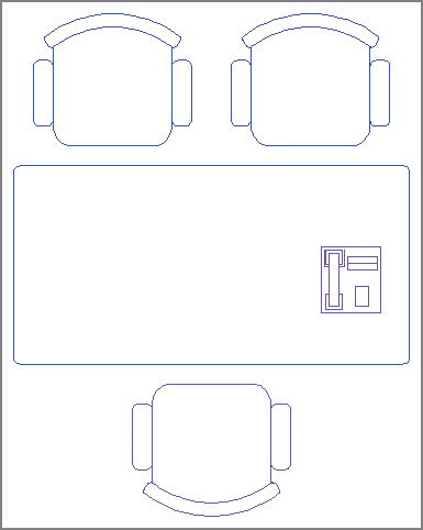
@80<0 for metric), and press Enter to copy a chair to the right (see
Figure 7-11). Press Esc to end the
COPY command.
9. Type I (for Insert), and press Enter. Type 180 in the Angle text box in the Rotation section of the Insert dialog box and click OK.
10. Hold Shift, right-click, and choose From in the context menu. Click the midpoint of the lower desk edge, and type @0,-3″ (or @0,-7 for metric), and press Enter. The Chair block reference appears 3″ (or 7 cm) down from the center of the desk.
11. Press Enter to repeat the last command (INSERT), and select Door from the Name drop-down list in the Insert dialog box. Select Specify On-Screen in the Rotation section and click OK.
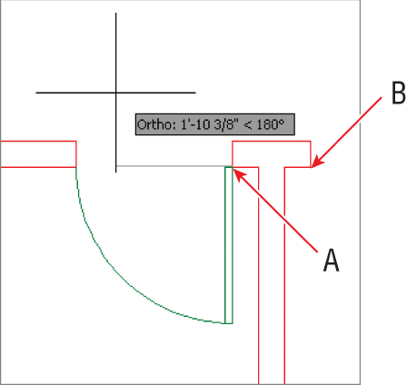
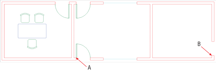
12. Click point A in the leftmost room, as shown in
Figure 7-12. Verify that Ortho mode is on in the status bar; if not, toggle it on. Move the cursor to the left to rotate the door into the proper orientation (see
Figure 7-12). Click on the drawing canvas to insert the door.
13. Press the spacebar to repeat the
INSERT command. Select Specify On-Screen in the Scale and Rotation sections of the Insert dialog box (see
Figure 7-13) and click OK.
14. Click point B, as shown in
Figure 7-12. The command prompt reads:
Specify insertion point or [Basepoint Scale Rotate]:
Specify scale factor <1>:
Specifying a negative scale factor mirrors the block about its base point.
Type -1 and press Enter.
15. The command prompt now says:
Specify rotation angle <0>: 180
Type 180 and press Enter. The door is inserted properly in the middle room.
16. Click the Copy tool in the Modify panel, select the door at the bottom of the middle room, and press Enter. Click points A and B shown in
Figure 7-14 to copy a door block into the room on the right. Press Esc to end the
COPY command.
Copying a block has the same effect as inserting a block: a new block reference is added to the drawing.
17. Select the new door in the rightmost room. Click its single blue grip to activate Grip Editing mode. Press the spacebar twice so that the command prompt reads as follows:
** ROTATE **
Specify rotation angle or
[Base point Copy Undo Reference eXit]:
Type 90 and press Enter to rotate the door block around its base point.
18. Save your work as Ch7-C.dwg (or Ch7-C-metric.dwg).
Editing Blocks
You can edit blocks after they have been defined and inserted into the drawing as block references. In addition to editing geometry, you can assign floating properties to control property inheritance, nest blocks within blocks, or explode blocks entirely. We’ll explore each of these topics in this section.
Editing Block Definition Geometry
Block definitions are not frozen in stone; you can redraw them after block references have been inserted multiple times in a drawing. In fact, this is one of the reasons to use blocks: efficient control over multiple objects from a single editable definition. In the following steps, you will alter the door block and see all its references update automatically.
1. If the file is not already open, go to the book’s web page, browse to Chapter 7, get the file Ch7-C.dwg (or Ch7-C-metric.dwg), and open it.
2. Zoom in on the lower door in the middle room.
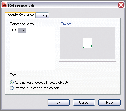
3. Select the door, right-click, and choose Edit Block In-Place from the context menu. Click OK in the Reference Edit dialog box that appears (see
Figure 7-15).
4. Click the Rotate tool on the Modify panel, select the door itself (not its swing), and press Enter. Click the hinge point and the command prompt reads:
Specify rotation angle or [Copy Reference] <0>:
Type -45 and press Enter.
5. Click the Trim tool in the Modify panel and press Enter. Click the portion of the wing that extends beyond the door to trim it off, and press Esc to end the TRIM command.
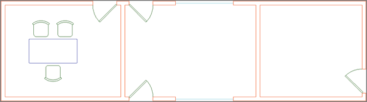
6. Expand the temporary Edit Reference panel on the ribbon’s Home tab, and click the Save Changes button. Click OK in the AutoCAD warning dialog box that appears, which says, “All reference edits will be saved.”
Figure 7-16 shows the result: All door references have been automatically updated with the new door geometry.
7. Save your work as Ch7-D.dwg (or Ch7-D-metric.dwg).
Assigning Floating Properties
When you set an object’s color, linetype, or lineweight to specific values such as Red, Hidden, or 0.5 mm, you are setting those properties explicitly. Explicit object properties assigned to objects in block definitions are retained when those blocks are inserted onto different layers in the drawing.
It is often advantageous to assign floating properties—either ByLayer or ByBlock—to the objects in block definitions. Floating properties allow block references to inherit properties from the layer on which they are inserted. Alternatively, you can override these inherited properties with explicit properties by assigning them to the block reference.
The Door layer has been current throughout this chapter, so the objects you drew to define the chair and door blocks reside on this layer. In the following steps, you will assign floating properties to the chair and door blocks.
1. If the file is not already open, go to the book’s web page, browse to Chapter 7, get the file Ch7-D.dwg (or Ch7-D-metric.dwg), and open it.
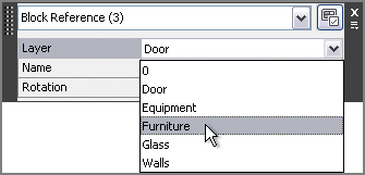
2. Click on each of the three chair block references to select them. Type
qp (for Quick Properties), and press Enter. Select Furniture from the Layer drop-down menu (see
Figure 7-17). Notice that the chairs are still green, even though the Furniture layer is blue. Click the Close box in the upper-right corner to close the Quick Properties palette, and press Esc to deselect.
You can use the
QP command as an alternative to toggling on Quick Properties mode on the status bar.
3. Select one of the chairs (it doesn’t matter which one), right-click, and choose Edit Block In-Place from the context menu. Click OK in the Reference Edit dialog box that appears.
4. Create an implied window to select all nine objects making up the chair.
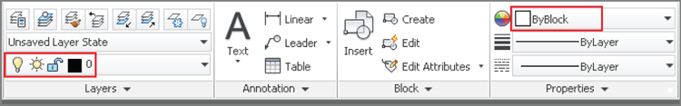
5. Type qp (for Quick Properties), and press Enter. Open the Color drop-down menu, and select ByBlock. Click the Quick Properties palette’s close box, and press Esc to deselect.

6. Expand the Edit Reference panel, and click the Save Changes button. Click OK in the AutoCAD warning dialog box. The chairs turn blue because the ByBlock floating property allows them to inherit the Furniture layer’s blue color.
7. Select the lower chair by clicking on it. Open the Color drop-down menu in the Properties panel, select Magenta, and press Esc. The chair turns magenta because ByBlock allows explicit properties assigned to the block reference to override inherited layer properties.
8. Open the Layer drop-down menu in the Layers panel, and set Layer 0 as the current layer.
9. Open the Layer drop-down menu again, and toggle off the Door layer. All the chairs and doors disappear because the geometry in the chair and door block definitions is on the Door layer. Toggle on the Door layer, and click outside the Layer drop-down menu to close it.

10. Select the lower chair, right-click, and choose Edit Block In-Place from the context menu. Click OK in the Reference Edit dialog box that appears.
11. Create an implied window to select all nine objects making up the chair.
12. Open the Layer drop-down menu, and select layer 0 to assign this layer to the selection. Press Esc to deselect the layer.
13. Expand the Edit Reference panel, and click the Save Changes button. Click OK in the AutoCAD warning dialog box.
Toggling off layer 0 does not hide block definition geometry referenced onto other layers.
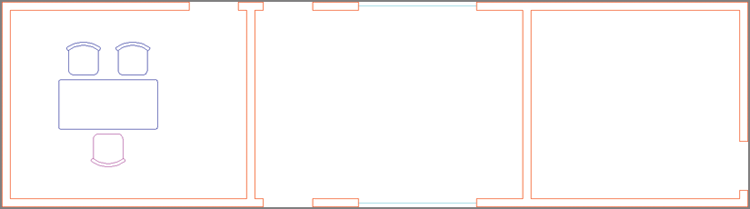
14. Open the Layer drop-down menu in the Layers panel, and toggle off the Door layer. The doors disappear but the chairs remain because the chair references have inherited the Furniture layer (see
Figure 7-18).
Blocks and Layer 0
I recommend that you always draw objects within block definitions on layer 0 so that block references will inherit the layer on which they are inserted. Layer 0 is the only layer that works like this for block definitions. In addition, you should assign floating properties for the color, linetype, and/or lineweight of the objects in the block definition.
15. Toggle on the Door layer.
16. Save your work as Ch7-E.dwg (or Ch7-E-metric.dwg).
Nesting Blocks
You can nest blocks within other blocks to simplify complex block definitions. However, you can’t create circular references where blocks reference themselves or you’d create an infinite loop. In the following steps, you’ll nest a phone block reference inside the desk block definition so that every desk you insert will have a phone on it.
1. If the file is not already open, go to the book’s web page, browse to Chapter 7, get the file Ch7-E.dwg (or Ch7-E-metric.dwg), and open it.
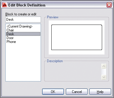
2. Type
BEDIT (for Block Editor), and press Enter. Select Desk in the Edit Block Definition dialog box that appears (see
Figure 7-19). Click OK.
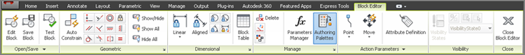
3. A temporary tab called Block Editor appears on the ribbon, and the selected block (desk) fills the drawing canvas. Click the Authoring Palettes tool on the Manage panel to toggle them off because they are not needed for this exercise (see
Figure 7-20).
The Block Editor is an alternative to editing blocks in place.
4. Type I (for Insert), and press Enter. Select Phone in the Name drop-down list. Deselect Specify On-Screen in the Scale and Rotation sections of the Insert dialog box and click OK.
5. Click an arbitrary point on the right side of the desk to insert the phone block reference there.
6. Select the phone block, type
qp (for Quick Properties), and press Enter. Change Layer Assignment to Equipment, click the close box to exit Quick Properties, and press Esc to deselect (see
Figure 7-21).
The phone is magenta because the objects in the phone block definition have floating properties that allow the Equipment layer’s magenta color to be inherited.
7. Click the Close Block Editor button on the Close panel. Click Save Changes To Desk in the Block – Changes Not Saved dialog box that appears.
8. Save your work as Ch7-F.dwg (or Ch7-F-metric.dwg).
Exploding Blocks
There are two commands that blow away blocks, leaving you with only their defining geometry: EXPLODE and XPLODE. The former has no options whatsoever; the latter offers many options dealing with what happens to object properties after the block is disassembled. Let’s explode a block using both methods:
1. If the file is not already open, go to the book’s web page, browse to Chapter 7, get the file Ch7-F.dwg (or Ch7-F-metric.dwg), and open it.
Use the
PURGE command to delete unused block definitions to make the drawing file smaller.
2. Type X (for Explode), and press Enter. Select the magenta chair, and press Enter.
3. Select the parts of the chair, and observe in the Layers panel that the objects are on layer 0 and in the Properties panel that their color is set to ByBlock (see
Figure 7-22). Press Esc to deselect.
4. Click the Undo button on the Quick Access toolbar. The block is re-created.
5. Type
xp (for Xplode), and press Enter. Select the magenta chair, and press Enter. The command prompt reads:
[All Color LAyer LType LWeight
Inherit from parent block Explode]
 <Explode>:
Type I (for Inherit from parent block), and press Enter.
6. Select all the parts of the chair, and observe that the objects are on the blue Furniture layer and their color is explicitly set to magenta. This time the disassembled objects received the layer assignment and object properties of the block reference.
7. Expand the Modify panel, and click the Set To ByLayer tool. The command prompt reads:
Change ByBlock to ByLayer? [Yes No] <Yes>:
Press Enter to accept the default Yes. Now the prompt says:
Include blocks? [Yes No] <Yes>:
Type N (for No), and press Enter. The SETBYLAYER command ends. The chair is now blue, because its color has been set to ByLayer.
8. Save your work as Ch7-G.dwg (or Ch7-G-metric.dwg).
Redefining Blocks
You already know that block definitions have names and that blocks are inserted by name. So what do you suppose happens if you define a new block using a name that has already been used in the drawing?
In the following steps, you are presented with just such a situation where you will have the opportunity to redefine a block definition. Any block references in the drawing will be automatically updated with the new definition.
1. If the file is not already open, go to the book’s web page, browse to Chapter 7, get the file Ch7-G.dwg (or Ch7-G-metric.dwg), and open it.
2. Zoom into the lower chair you exploded in the previous section.
3. Click the Rectangle tool on the Draw panel. The command prompt reads:
Specify first corner point or [Chamfer Elevation
Fillet Thickness Width]:
Type
F (for Fillet), and press Enter. The prompt now says:
Specify fillet radius for rectangles <0′-0″>:
Type 1″ (or 3 cm), and press Enter. The rectangle will have rounded corners.
4. For the first corner, click point A, as shown in
Figure 7-23. Then type
@3,-10 (or
@7,-25 for metric), and press Enter to complete the
RECTANGLE command.
5. Click the Mirror tool in the Modify panel. Type
L (for Last), and press Enter twice. The command prompt reads:
Specify first point of mirror line:
Snap to the midpoint of the chair’s front edge, toggle on Ortho on the status bar, move the cursor downward, and click on the drawing canvas to specify the second point of the mirror line. Press Enter to complete the
MIRROR command (see
Figure 7-24).
6. Select all objects in the chair and its armrests. Open the Layer drop-down menu, and select layer 0 to change the assignment of the selected objects.
7. Type B (for Block), and press Enter. Type Chair in the Name field in the Block Definition dialog box. Click the Pick Point button, and then snap to the midpoint of the chair’s front edge.
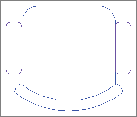
8. Select the Convert To Block radio button in the Objects section of the Block Definition dialog box and click OK. Click Redefine Block in the Block – Redefine Block dialog box that appears.
Figure 7-25 shows the result: All three chair block references are updated.
9. Unfortunately the redefined chair block references didn’t preserve their original orientations. No matter; click the Mirror tool on the Modify panel, select the top two chairs, and press Enter. Snap to the front edge of one of the seats, move the cursor to the right, and click on the drawing canvas. The command prompt reads:
Erase source objects? [Yes No] <N>:
Type
Y (for Yes), and press Enter. The chairs are now oriented correctly (see
Figure 7-26).
10. Save your work as Ch7-H.dwg (or Ch7-H-metric.dwg).
Working with Groups
Groups are a means of organizing objects that is less formal than blocks. Groups don’t need to be named, nor do they require base points as do blocks. You can toggle group selection on and off so that you can manipulate the entire group as a unit or access individual members of the group at will. You can’t redefine the many with the few as you can with blocks, however. That said, it’s certainly convenient to be able to manipulate many blocks with a few groups. In the following steps, you will group the desk and chairs, copy this group into adjacent rooms, and make adjustments to various blocks within the groups.
1. If the file is not already open, go to the book’s web page, browse to Chapter 7, get the file Ch7-H.dwg (or Ch7-H-metric.dwg), and open it.
2. Click the Group tool on the Groups panel on the ribbon’s Home tab. Select the desk and the three chairs surrounding it, and then press Enter.
3. Click the Copy tool on the Modify panel, click the group to select it, and press Enter. Click an arbitrary point inside the desk, and then click in the middle and right rooms to copy the group twice. Press Esc to end the COPY command.
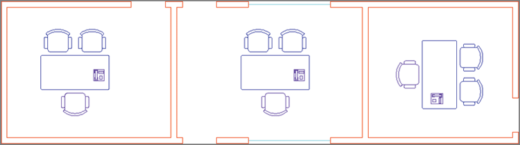
4. Click the Rotate tool on the Modify panel, select the group in the room on the right, and press Enter. Click an arbitrary point inside the desk, type
-90, and press Enter (see
Figure 7-27).
5. Click the Group Selection On/Off toggle in the Groups panel (turning it off).
6. Select the lower chair in the middle room, and press the Delete key.
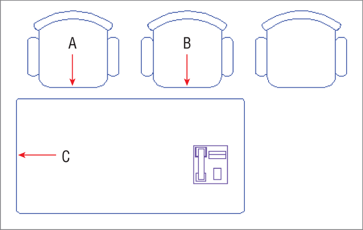
7. Click the Copy tool on the Modify panel, select the chair on the right in the middle room, and press Enter. Snap to the midpoints at points A and B shown in
Figure 7-28 and press Enter. A third chair is copied so that all three are equidistant.
8. Click the Mirror tool on the Modify panel, select the three chairs in the middle room, and press Enter. Click point C shown in
Figure 7-28, move the cursor to the right, and click in the drawing canvas to complete the mirror line. Press Enter to mirror three more chairs on the opposite side of the desk.
9. Type xp (for Xplode), and press Enter. Select the desk, and press Enter. Type I (for Inherit from parent block), and press Enter.
10. Click the Stretch tool on the Modify panel; select the right edge of the desk with a crossing window so that the top, bottom, and right edges are selected; and press Enter. Click an arbitrary point inside the desk, move the cursor to the right, type 2′6″ (or 80 for metric), and press Enter. The desk is enlarged.
11. Select the phone block on the desk, and press the Delete key.
12. Click the Group Edit tool on the Groups panel, select the upper-left chair in the middle room, and press Enter. The command prompt reads:
Enter an option [Add objects Remove objects REName]:
Type A (for Add objects), and press Enter. Select all six chairs and the desk, and then press Enter.
13. Click the Group Selection On/Off toggle in the Groups panel (turning it on). Hover the cursor over the desk, and observe that the entire group is highlighted (see
Figure 7-29).
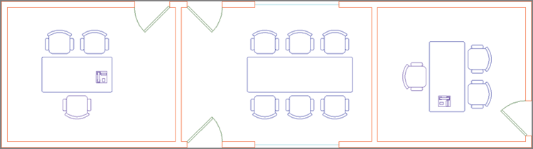
14. Open the Layer drop-down menu, and toggle on the Door layer.
Figure 7-30 shows the final result.
Your drawing should now resemble Ch7-Final.dwg (or Ch7-Final-metric.dwg), which is available among the book’s download files at www.sybex.com/go/autocad2014essentials.
The Essentials and Beyond
In this chapter, you learned how to organize objects into blocks and groups. More specifically, you defined, inserted, edited, nested, exploded, and redefined blocks. You saw how floating properties and layer 0 affect property inheritance when block references are inserted into a drawing. Finally, you worked with groups, manipulated them as whole units, accessed their individual members, and added objects to an existing group. In short, you now have the skills to organize objects for efficient drafting.
Additional Exercise
Explore the BCONSTRUCTION command on your own. It is used to convert geometry into construction geometry that is only visible within the Block Editor for layout purposes. For example, try drawing a mirror line down the center line of the chair block and converting it to construction geometry with the BCONSTRUCTION command. The mirror line serves as a helpful visual reference while in the Block Editor, but the construction geometry will not be displayed in the block reference.