Chapter 9
Working with Blocks and Xrefs
In Chapter 7, “Organizing Objects,” you learned how to define and reference blocks within a single drawing in the AutoCAD® program. In this chapter, you will create and insert global blocksfrom outside the current drawing. Harnessing the power of a search engine, you’ll cast a net across multiple drawings to locate specific blocks and a variety of other content. Once key content is found, you will place it on tool palettes for quick access in the future. In addition, you will make external references (Xrefs) to drawings outside the current file.
- Working with global blocks
- Accessing content globally
- Storing content on tool palettes
- Referencing external drawings and images
Working with Global Blocks
Global blocks are drawing files that you will later insert as blocks into another drawing. In this section, you will learn how to write local blocks to files, insert a drawing file as a local block, and redefine local blocks with global blocks.
Writing a Local Block Definition to a File
In the following steps, you will export one of the current drawing’s block definitions to an individual drawing file. In addition, you will open the newly created file and alter its contents.
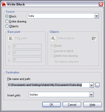
2. Type
W (for Write block), and press Enter. Select the Block radio button in the Source area of the Write Block dialog box. Select Sofa from the Block drop-down. Select Inches from the Insert Units drop-down in the Destination area (see
Figure 9-1). Click OK, and the geometry within the Sofa block definition is written to
Sofa.dwg.
The Sofa block that was written to
Sofa.dwg does not itself have a Sofa block definition; only the geometry was transferred to the new file.
3. Click the Open tool on the Quick Access toolbar. Browse to the following folder:
C:Documents and Settings<your user name>My Documents
4. Click Zoom Extents on the Navigation bar.
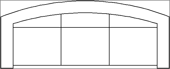
5. Click the Erase tool on the Modify panel, select the two arcs in the sofa’s backrest, and press Enter.
6. Toggle on Ortho mode on the status bar.
7. Toggle on Object Snap on the status bar. Right-click the Object Snap toggle, and select Endpoint if it is not already selected.
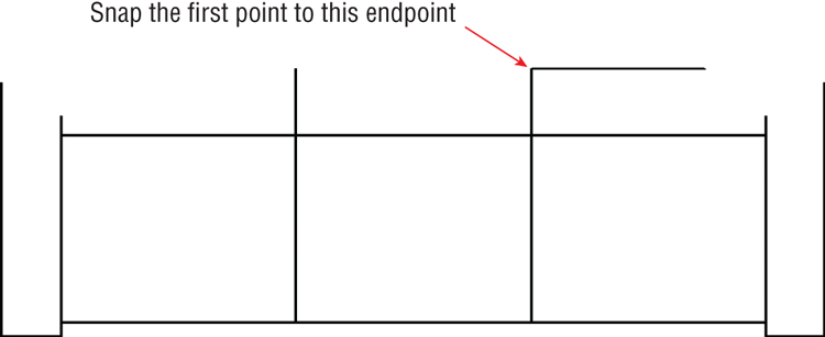
8. Click the Line tool on the Draw panel. Snap the first point of the line to the endpoint shown in
Figure 9-3. Move the cursor to the right, and click an arbitrary second point. Press Esc to end the
LINE command.
9. Click the Fillet tool on the Modify panel. Press F2 to open the Command window, and verify that the command prompt says the following:
Current settings: Mode = TRIM, Radius = 0'-0"
If the radius is not 0, type R (for Radius), press Enter, type 0, and press Enter again. Select the line you just drew, and then click the inner line on the right arm of the sofa.
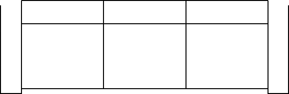
10. Press the spacebar to repeat the
FILLET command. Click the inner line on the left arm of the sofa, and then click the back line.
Figure 9-4 shows the result.
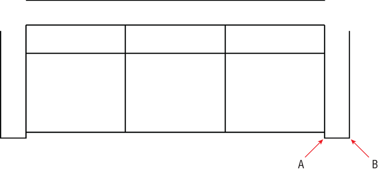
11. Click the Offset tool on the Modify panel. Click points A and B in
Figure 9-5 to set the offset distance. Select the back line of the sofa, and then click above it to offset another line.
12. Click the Fillet tool on the Modify panel. Select the line you just offset, and then click the outer line on the right arm of the sofa.
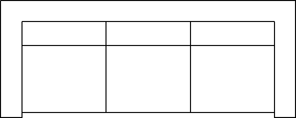
13. Press the spacebar to repeat the
FILLET command. Click the outer line on the left arm of the sofa, and then click the top back line. The sofa redesign is complete (see
Figure 9-6).
14. Click the Save As tool on the Quick Access toolbar. Type Sofa2.dwg in the File Name text box, and then click the Save button.
15. Type CLOSE, and press Enter to close the file you just saved.
Inserting a Drawing as a Local Block
When you insert a DWG file that has global scope into the current drawing, it comes in as a block. In the following steps, you will insert the new sofa block twice into the same file in which you started this chapter:
1. If the file is not already open, go to the book’s web page, browse to Chapter 9, get the file Ch9-A.dwg, and open it.
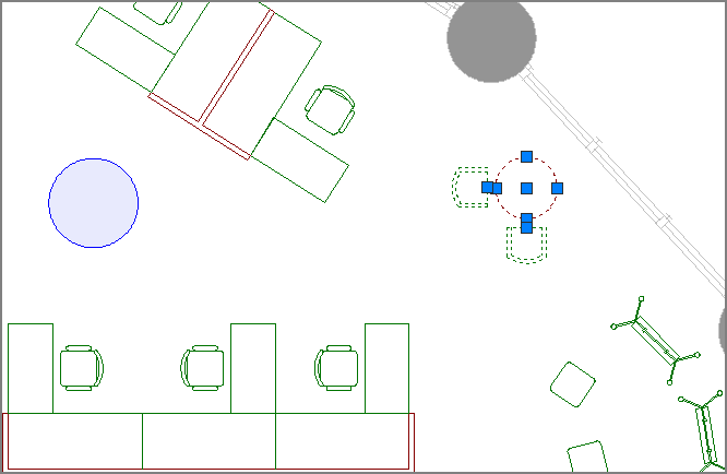
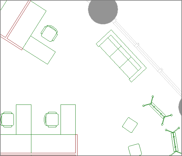
2. Zoom into the upper-right building quadrant, select the two armchairs and round side table, and press the Delete key (see
Figure 9-7).
3. Toggle off Object Snap on the status bar.
4. Click the Make Object’s Layer Current tool in the Layers panel. Click the Manager’s chair and A-furn becomes the current layer.
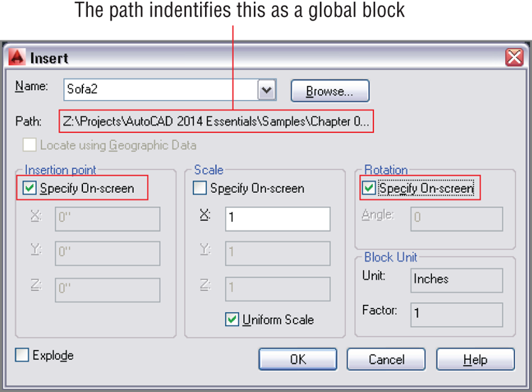
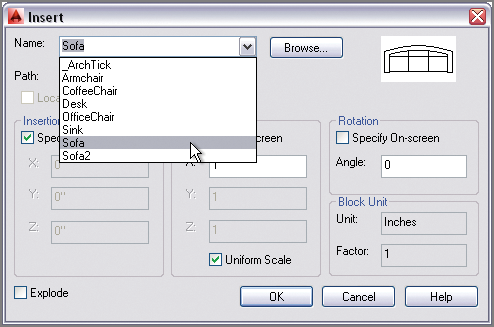
5. Click the Insert tool on the Block panel. The Sofa2 block is not yet defined in this drawing’s block table, so you won’t find it in the Name drop-down. Click the Browse button and locate the
Sofa2.dwg file you saved in the previous exercise, or use the
Sofa2.dwg file provided in the
Samples folder for Chapter 9. Select Specify On-screen for both Insertion Point and Rotation in the Insert dialog box (see
Figure 9-8) and click OK.
6. Click approximately where you deleted the armchairs and side table to insert a Sofa2 block reference in the drawing, and estimate the rotation angle so that the sofa is parallel to the exterior wall (see
Figure 9-9).
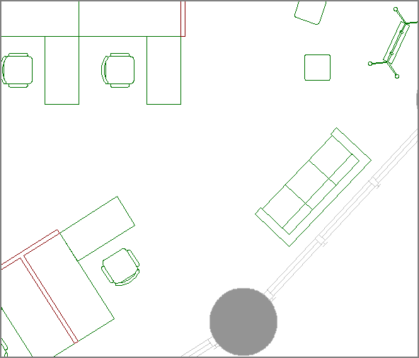
7. Pan down to the lower-right building quadrant. Delete the two armchairs and side table there.
8. Type I (for Insert), and press Enter. Sofa2 is already selected in the Name drop-down. No path is listed in the Insert dialog box this time because Sofa2 was defined as a local block when you inserted it in step 5. Click OK.
9. Click approximately where you deleted the armchairs and side table to insert a Sofa2 block reference in the drawing, and rotate it so that the sofa is again parallel to the exterior wall (see
Figure 9-10).
10. Save your work as Ch9-B.dwg.
Redefining Local Blocks with Global Blocks
When you insert a global block with the same name as a local block, the local block is redefined. In the following steps, you will redefine the original sofa block with the new sofa design:
1. Click the Open tool on the Quick Access toolbar. Browse to the following folder:
C:Documents and Settings<your user name>My Documents
Sofa2.dwg is provided on the book’s web page if you are jumping in here.
2. Click the Save As tool on the Quick Access toolbar. Save the file as Sofa.dwg, and click Yes when prompted to replace the file.
3. Type CLOSE, and press Enter.
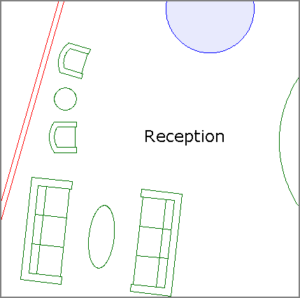
4. If the file is not already open from the previous section, go to the book’s web page, browse to Chapter 9, get the file Ch9-B.dwg, and open it. Pan over to Reception.
5. Click the Insert tool in the Block panel. Open the Name drop-down, and select Sofa in the list. The preview image in the upper right shows that the local block definition is based on the curved-back design (see
Figure 9-11).
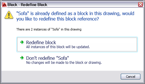
6. Click the Browse button in the Insert dialog box. Select the
Sofa.dwg file you saved in step 2. Click OK in the Insert dialog box, and the Block – Redefine Block dialog box appears (see
Figure 9-12). Notice that it says that there are two Sofa block references in the drawing. These are two sofas in Reception. Click Redefine Block.
7. The two sofas in Reception are redefined with the straight-back design (see
Figure 9-13). Press Esc to cancel the
INSERT command; you do not need to insert a new block reference.
8. Save your work as Ch9-C.dwg.
Accessing Content Globally
The Content Explorer allows you to search for—and insert—content from within other drawings on your local area network (LAN) and on Autodesk Seek on the Web. Using the Content Explorer to locate and insert blocks is much more efficient than writing blocks to files and then inserting the resulting files into drawings, as you learned in the previous section.
There are two reasons for the increased efficiency of the Content Explorer:
- You can access all the blocks within every file in your search path.
- Harnessing the power of a search engine gets you to what you are looking for much faster than a manual search.
Any file that can be opened, imported, or attached is indexed in the Content Explorer. In the following steps, you will use the Content Explorer to search for blocks and other types of content:
1. If the file is not already open, go to the book’s web page, browse to Chapter 9, get the file Ch9-C.dwg, and open it.
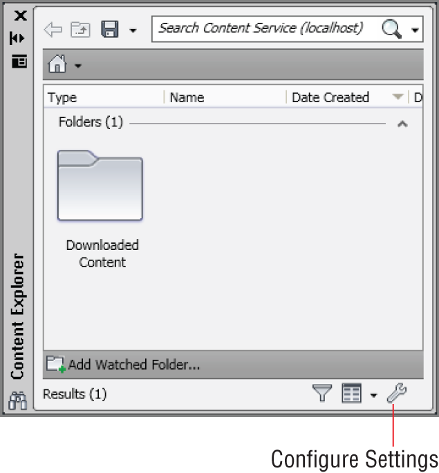
2. Click the Plug-Ins tab on the ribbon, and click the Explore tool on the Content panel; the Content Explorer appears (see
Figure 9-14).
3. Click the Configure Settings button in the Content Explorer.
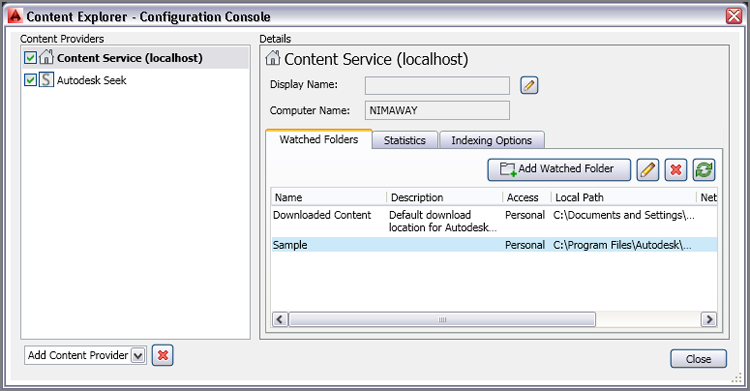
4. Click the Add Watched Folder button in the Configuration Console dialog box. Add the following path (if it’s not already there):
C:Program FilesAutodeskAutoCAD 2014Sample
Click OK in the Edit Watched Folder dialog box that appears. AutoCAD goes to work indexing the watched folder (see
Figure 9-15). Click the Close button in the Configure Console dialog box. The indexing process will take approximately 10 minutes before all the content in the Sample folder will be available in the Content Explorer.
The Content Explorer’s search engine indexes files as they are added to the Watched Folders list. This process can take a few minutes when folders are first added, but after that, the search time is negligible.
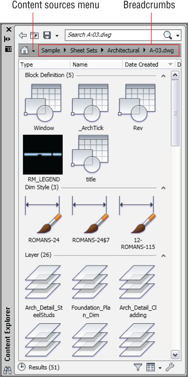
5. Double-click the
Sample folder that appears in the Content Explorer. Then double-click Sheet Sets, Architectural, and
A-03.dwg. The Content Explorer shows all the block references, block definitions, layers, layouts, and styles present in the drawing (see
Figure 9-16).
6. You can click on any of the
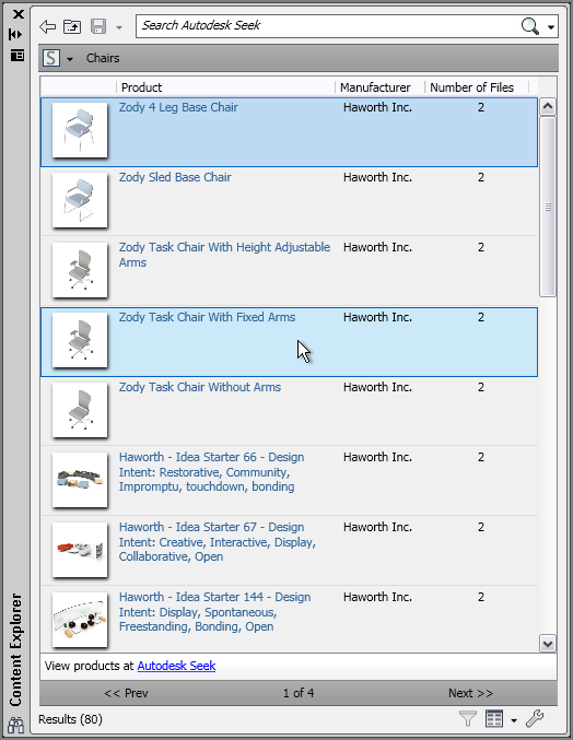
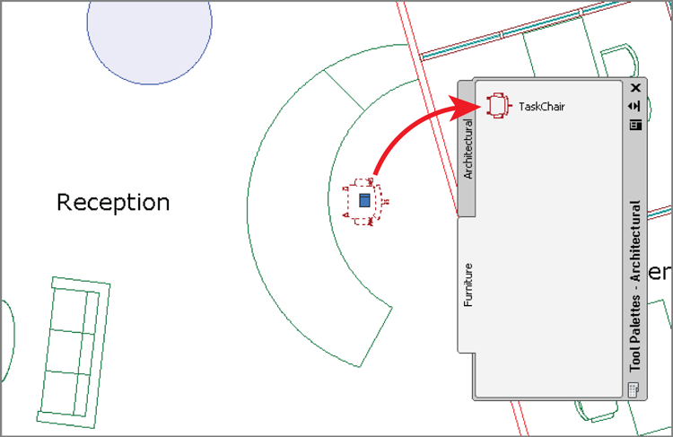
breadcrumbs to go to specific folders in the local path. Alternatively, you can access online content. Open the Content Sources menu, and select Autodesk Seek. Double-click the
Chairs folder, and select this item in the list: Zody Task Chair With Fixed Arms (see
Figure 9-17).
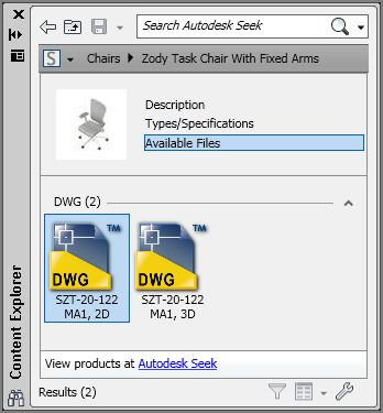
7. Double-click the selected item. The page that appears in the Content Explorer lists the available files. Right-click the first icon—SZT-20-122 MA1, 2D—for the two-dimensional representation of this chair (see
Figure 9-18) and choose Insert. The cursor displays a thumbnail image of the file with a progress bar.
8. When the download is complete, you may be prompted to create a new block name for the content. Type TaskChair in the Substitute Block Name dialog box that appears and click OK.
9. Choose an arbitrary location in Reception, and click to insert the chair. Press Enter repeatedly to accept the default scale, rotation, and multiple attribute values.
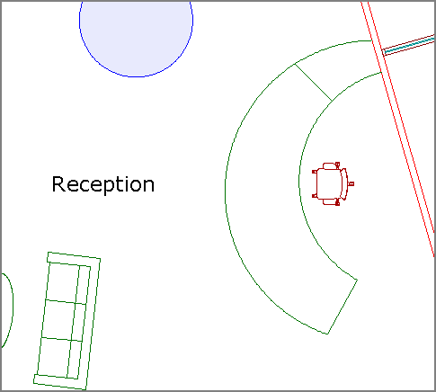
10. Delete the receptionist’s chair, move the new chair into its place, and rotate it to face the room.
Figure 9-19 shows the downloaded chair behind the receptionist’s desk.
Downloaded content will not necessarily conform to your organization’s layer standard.
11. Save your work as Ch9-D.dwg, and close the Content Explorer.
Storing Content on Tool Palettes
Tool palettes are used for storing just about any type of content for quick reuse. You create tools on a palette by dragging objects—including blocks, hatches, images, dimensions, tables, lights, cameras, materials, visual styles, and Xrefs—onto the palette from any saved drawing.
In the following steps, you’ll create a new palette, drag a sofa onto it, and then use the tool to add another sofa:
1. If the file is not already open, go to the book’s web page, browse to Chapter 9, get the file Ch9-D.dwg, and open it.
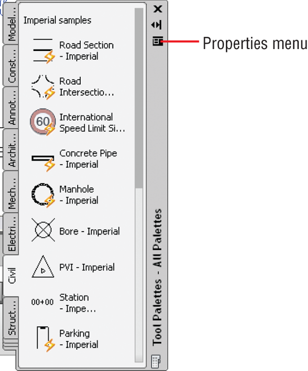
2. Select the ribbon’s View tab, and click the Tool Palettes button on the Palettes panel (see
Figure 9-20).
3. Open the Properties menu on the Tool Palettes panel. The items listed at the bottom of the menu are palette groups. Select Architectural. The Architectural palette group contains one palette, which is also called Architectural.
4. Reopen the Tool Palettes panel’s Properties menu, and select New Palette. Type Furniture, and press Enter. A second palette appears under Architectural.
5. Select the receptionist’s chair. Drag this chair (not using a grip) onto the Furniture palette. TaskChair appears with a preview icon (see
Figure 9-21).
Blocks dragged to tool palettes are global blocks that can be inserted into any drawing.
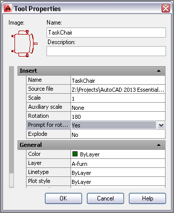
6. Right-click the TaskChair tool in the Furniture palette, and choose Properties from the context menu. Change Prompt For Rotation to Yes in the Tool Properties dialog box that appears (see
Figure 9-22). Click OK.
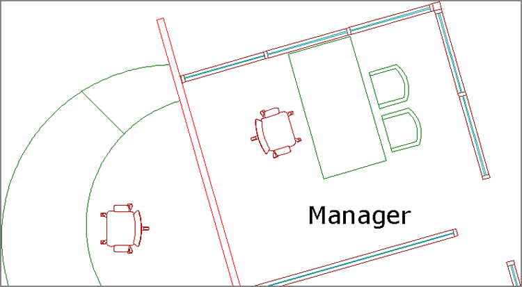
7. Select the Manager’s offices on the other side of the wall behind the receptionist’s chair. Type UNGROUP, and press Enter. Erase the manager’s chair immediately behind the receptionist’s chair.
8. Click the TaskChair tool on the Furniture tool palette. Click the place where the manager’s chair used to be, and then specify the rotation by clicking a second time. Click OK or Cancel to close the Edit Attributes dialog box that appears.
Figure 9-23 shows the result.
9. Close the Tool Palettes, and save your work as Ch9-E.dwg.
Referencing External Drawings and Images
External references (called Xrefs) are a more dynamic alternative to blocks. Xrefs linked to the current drawing are automatically updated every time the current drawing is opened. Blocks, on the other hand, must be edited in place or redefined when they are changed. The real efficiency with Xrefs comes when you link one file into multiple drawing files, because changes made to the linked file are automatically reloaded in all the files that have the Xref attached.
This is just one example of using Xrefs in the case of a high-rise building. Xrefs can be used in every discipline whenever you want the advantages they provide.
In the following steps, you will externally reference a core (elevators, stairs, shafts) and shell (exterior envelope) drawing into the drawing containing items owned by the building tenant (walls, doors, furniture, and so on). The advantage of working this way is that the core and shell generally do not change from floor to floor, whereas the tenant improvement drawings are typically unique to each floor. Changes to the core and/or shell can be made in separate drawings that are linked to all the individual tenant drawings.
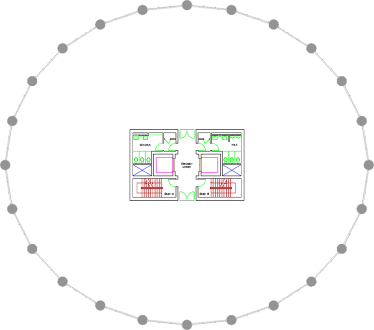
1. Go to the book’s web page, browse to Chapter 9, get the file
Ch9-CoreShell.dwg, and open it.
Figure 9-24 shows the building core and shell.
2. Return to the book’s web page, browse to Chapter 9, get the file
Ch9-F.dwg, and open it.
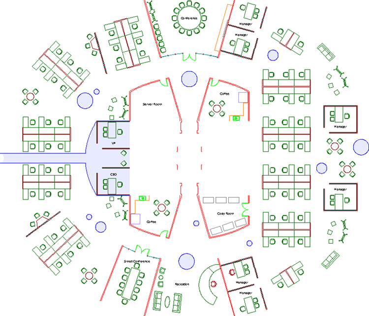
Figure 9-25 shows the objects owned by the tenant.
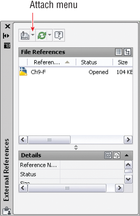
3. Select the ribbon’s View tab, and click the External References Palette button in the Palettes panel. Open the Attach menu, as shown in
Figure 9-26.
4. Select Attach DWG from the menu. Select the file Ch9-CoreShell.dwg, and click Open in the Select Reference dialog box.
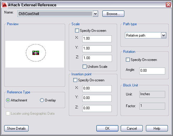
5. In the Attach External Reference dialog box that appears, deselect Specify On-Screen in the Insertion Point area (see
Figure 9-27). Click OK.
You can externally reference DWG, DWF, DGN, PDF, and a variety of image file formats.
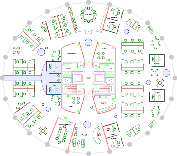
6. The core and shell appear faded with respect to the tenant drawing (see
Figure 9-28).
You can adjust the amount of fading the Xref displays in the
OPTIONS command on the Display tab within the Options dialog box.
7. Select the core or shell to select the single Xref object. Click the Open Reference tool on the Edit panel of the External Reference tab that appears on the ribbon.
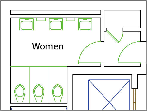
8. Redesign the Women’s washroom so that it has three sinks, as shown in
Figure 9-29.
9. Type CLOSE, and press Enter twice to close and save Ch9-CoreShell.dwg.
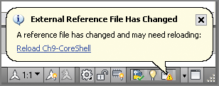
10. A balloon appears in the drawing status bar informing you that an external reference has changed (see
Figure 9-30). If no notification balloon appears, right-click the Xref that needs to be reloaded in the External References palette and choose Reload. Click the hyperlinked blue text to reload the Ch9-CoreShell Xref. The changes made to the Women’s washroom are now visible in the tenant drawing.
11. Save your work as Ch9-G.dwg.
The Essentials and Beyond
In this chapter, you learned how to work with global blocks, the Content Explorer, Tool Palettes, and Xrefs. You learned how to increase drawing and editing efficiency by using blocks and Xrefs. You can now access and work with content beyond the current drawing. This is the key to working in a team, because team members regularly need to share content with one another. Global blocks and Xrefs are the means for exchanging design data within a team. The Content Explorer and the Tool Palettes feature make finding and using design data much easier.
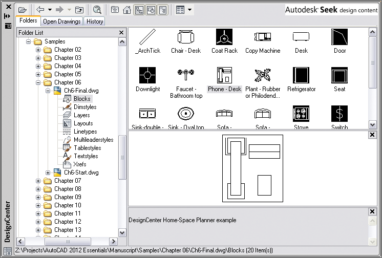
Additional Exercise
Explore the Autodesk Design Center using the ADC command. The Design Center is similar to the Content Explorer but without the search engine functionality. Reopen Ch9-G.dwg if it’s not still open. Expand the folder list in the DesignCenter palette, and navigate to the Chapter 06 folder on your hard drive; then expand Ch6-Final.dwg. Select Blocks, and then drag the Phone-Desk block into the drawing canvas of Ch9-G.dwg. Move this phone to the President’s desk.