Chapter 10
Creating and Editing Text
Text is an essential part of every drawing. You use the written word to clarify graphical depictions and delineate your design intent with specific language. It’s good to remember that drawings can be used as part of legal construction documents, and you typically need to clarify your design intent with text that appears on the drawings themselves. In this chapter, you’ll learn how to style text, how to write both lines and paragraphs of text using specialized commands, and how to edit existing text.
- Creating text styles
- Writing lines of text
- Writing and formatting paragraphs of text using MTEXT
- Editing text
Creating Text Styles
The AutoCAD® software can’t help you with your grammar or linguistic style, but it can style the appearance of text. Text styles associate specific fonts, optional text heights, and special effects with text objects. In the following steps, you will create the text styles that you will use in the next section when creating text objects.
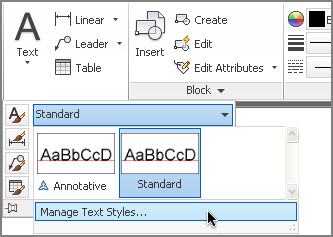
2. On the ribbon’s Home tab, expand the Annotation panel and open the first drop-down menu (for text styles). Every drawing has both an Annotative and Standard style by default. Select Manage Text Styles at the bottom of the panel (see
Figure 10-1).
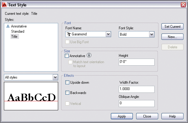
3. Click the New button in the Text Style dialog box that appears. Type Title in the New Style dialog box and click OK.
4. Open the Font Name drop-down and select Garamond. The symbol next to the font name indicates this is a TrueType font. Set Font Style to Bold, and deselect Annotative (see
Figure 10-2). Click the Apply button.
TrueType is the most common format for fonts on both Mac OS and Windows. The names that appear in the Font Name drop-down reflect the fonts installed on your operating system.
5. Select Standard in the Styles list on the left side of the Text Style dialog box. Open the Font Name drop-down and select simplex.shx. The symbol next to the font name indicates this is a shape-based font that is specific to AutoCAD. Type 1′-0″ (or 30 cm) in the Height text box. Type 0.8000 as the Width Factor value in the Effects area so that this style will be 20 percent narrower than the default. Click the Apply, Set Current, and Close buttons (in that order).
AutoCAD SHX fonts were designed to optimize motion in pen plotters (now obsolete) but are still commonly used today as simple fonts suitable for architectural and engineering lettering.
6. Save your work as Ch10-B.dwg or Ch10-B-metric.dwg. The styles you created are saved within the drawing even though you can’t see them on the drawing canvas.
Writing Lines of Text
You will use the TEXT command when you want to create a single line of text. TEXT creates independent objects on every line so that these objects are suitable for use in symbols or labels on drawings. You will learn how to create text that fits within a specified linear distance so that the text fits within a rectangle or circle, for example. In addition, you will justify text so that it can be easily reused and its content changed without having to reposition the text every time to maintain alignment with surrounding geometry. You will also discover that text objects can be manipulated and duplicated using many of the commands you already know.
Creating Text to Fit
There are many situations where you will want to fit text within geometric objects. For example, you might employ a rectangular symbol in which a number of room names might be displayed in each case where the symbol is to be used. If a text object were always to fit perfectly within the given rectangle, it would simplify having to create rectangles of different widths for each room in which the symbol is to be used. In the following steps, you will create single-line text, justified to fit within just such a rectangular symbol:
1. If the file is not already open from performing the previous step, go to the book’s web page, browse to Chapter 10, get the file Ch10-B.dwg or Ch10-B-metric.dwg, and open it.
2. Zoom in on the small rectangle in the upper-left corner of the drawing canvas.
3. Click the Offset tool in the Modify panel, type 4″ (or 10 cm) to set the offset distance, and press Enter. Select the small rectangle, and then click a point inside the rectangle to offset another smaller rectangle inside.
4. Toggle on Object Snap on the status bar. Right-click the same button, and select both Endpoint and Center running object snap modes if they are not already selected.
5. Open the menu under the Text tool on the Annotation panel, and select Single Line from the menu. The command prompt reads:
Current text style: "Standard"
Text height: 1'-0" Annotative: No
Specify start point of text or [Justify Style]:
Type J (for Justify), and press Enter.
6. The command prompt now reads as follows:
Enter an option [Align Fit Center Middle
Right TL TC TR ML MC MR BL BC BR]:
Type F (for Fit), and press Enter.
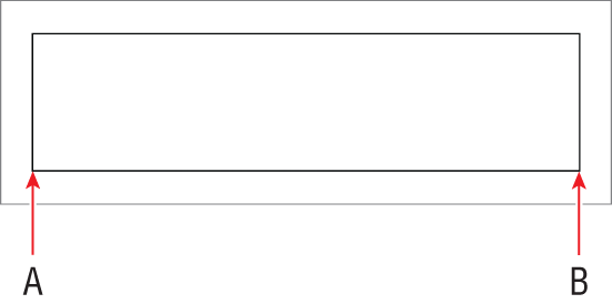
7. Click points A and B in
Figure 10-3. A blinking cursor appears.
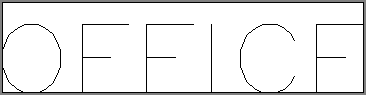
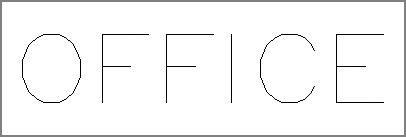
8. Type
OFFICE, and press Enter twice. The
TEXT command ends and the single line of text appears on the drawing canvas (see
Figure 10-4).
9. Select the inner rectangle, and press the Delete key.
10. Toggle on Ortho mode on the status bar.
11. Click the Move tool on the Modify panel, type
L (for Last), and press Enter twice. Click an arbitrary point on the drawing canvas, move the cursor upward from that point, type
2″ (or
5 cm), and press Enter. The text moves up so that the word OFFICE is centered within the rectangle (see
Figure 10-5).
12. Save your work as Ch10-C.dwg or Ch10-C-metric.dwg.
Justifying Text
AutoCAD has numerous options that let you justify text to suit almost any conceivable geometric situation. In the following steps, you will align text so that it appears centered within a callout symbol indicating the drawing and sheet number:
1. If the file is not already open from performing the previous step, go to the book’s web page, browse to Chapter 10, get the file Ch10-C.dwg or Ch10-C-metric.dwg, and open it.
2. Click the Pan tool in the Navigation bar, and drag from right to left to reveal the circle with a line running through it. Press Esc to exit the Pan tool.
3. Type
TEXT, and press Enter. The command prompt reads:
Specify start point of text or [Justify Style]:
Type J (for Justify), and press Enter.
4. The command prompt now reads:
Enter an option [Align Fit Center Middle Right
TL TC TR ML MC MR BL BC BR]:
If you press Enter when the command prompt says Specify start point of text or [Justify Style]:, the new text object will appear directly below the previous text object on the next line. Be aware that each text line is a separate object, however.
Type MC (for Middle Center), and press Enter. Type CEN (for Center), and click the circle to make the center of the circle the middle point of the text. Press Enter to accept 0 as the default rotation angle. Type 3, and press Enter twice.
5. Click the Move tool on the Modify panel, type L (for Last), and press Enter twice. Click an arbitrary point on the drawing canvas, move the cursor upward from that point, type 18″ (or 40 cm), and press Enter. The text is centered within the upper semicircle.
6. Save your work as Ch10-D.dwg or Ch10-D-metric.dwg.
Transforming and Creating Text
Text objects can be transformed with the same commands you might use on other types of objects—commands such as MOVE, COPY, ROTATE, SCALE, and MIRROR. In the following steps, you will mirror and copy existing text to create new text objects that you will alter later in the “Editing Text” section. In addition, you will create new text in a different style.
1. If the file is not already open, go to the book’s web page, browse to Chapter 10, get the file Ch10-D.dwg or Ch10-D-metric.dwg, and open it.
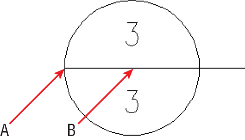
2. Click the Mirror tool on the Modify panel, select the text object (3), and press Enter. Click the Endpoint at point A and the Center point at B, as shown in
Figure 10-6, to define the mirror. The command line reads:
Erase source objects? [Yes No] <N>:
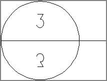
3. Press Enter to accept the default, No, and the MIRROR command is done.
4. Click the Copy tool on the Modify panel, type L (for Last), and press Enter twice. Click an arbitrary point on the drawing canvas, move the cursor to the right from this point, type 4′ (or 140 cm), and press Enter twice. A new text object is created to the right of the text you mirrored in the previous step.
Transforming and editing existing text is an alternative to creating new text objects from scratch.
5. Click the Single line text tool on the Annotation panel. The command prompt reads:
Specify start point of text or [Justify Style]:
6. Type S (for Style), and press Enter. Type Title (the name of one of the styles you created in the “Creating Text Styles” section), and press Enter. Title is now the current style.
7. Click point A in
Figure 10-7 as the start point of text. The command prompt now reads:
Specify height <6">:
Mirroring Text
Set the MIRRTEXT system variable to 1 to mirror text as well as objects with the MIRROR command. Text mirrored with MIRRTEXT set to 1 appears backward or upside down.
8. Type 1′-6″ (or 45 cm) to specify the text height and press Enter. Press Enter again to accept a default rotation of 0 degrees (horizontal). Type Drawing Title, and press Enter twice to end the TEXT command.
You are only prompted to enter a text height in text objects whose style’s text height is set to 0.
9. Save your work as Ch10-E.dwg or Ch10-E-metric.dwg.
Writing and Formatting Paragraphs of Text Using MTEXT
The MTEXT command is a word processing program within AutoCAD that treats all the lines and paragraphs you write as a single object. The powerful MTEXT command gives you word wrap, per-letter style overrides, tabs, inline spell checking, control over line spacing, bulleted and numbered lists, column formatting, and many other features.
MTEXT is ideally suited to writing general notes on drawings and other lengthy blocks of text. In the following steps, you will create and format some unusual general notes. Instead of typing multiple paragraphs, you’ll import one of the most famous monologues in the English language and turn it into a series of hypothetical steps.
1. If the file is not already open, go to the book’s web page, browse to Chapter 10, get the file Ch10-E.dwg or Ch10-E-metric.dwg, and open it. In addition, get the file Hamlet.txt and double-click the file to open it in Notepad on the PC or TextEdit on the Mac. Select Format ⇒ Word Wrap in Notepad to see the text wrap onto multiple lines if necessary.
2. Press Alt+Tab to switch back to AutoCAD. Pan over to the large rectangle in Ch10-E.dwg or Ch10-E-metric.dwg.
Text objects are created in the current style.
3. Type ST (for Style), and press Enter. Double-click Standard in the Styles list on the left side of the Text Style dialog box. Standard is now the current style. Click the Close button.
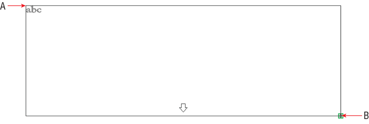
4. Open the menu under the Text tool on the Annotation panel, and select Multiline Text from the menu. Click points A and B, as shown in
Figure 10-8.
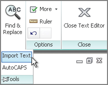
5. The Text Editor context tab appears on the ribbon. Expand its Tools panel, and click the Import Text button, as shown in
Figure 10-9.
Context Tab or In-Place Editor
If you are in a workspace that doesn’t support the ribbon (such as AutoCAD Classic), then the Text Editor context tab cannot appear. Instead, you will see the In-Place Editor, which has most of the same functionality.
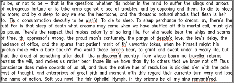
6. Click
Hamlet.txt in the Select File dialog box that appears. Click Open, and text appears within the large rectangle (see
Figure 10-10). The built-in spell checker identifies misspelled words by underlining them in red. Perhaps this is not surprising for English written 400 years ago, but in your own projects, right-click any underlined word that seems incorrect (which most likely wouldn’t include company or product names, or technical jargon) for correctly spelled suggestions.
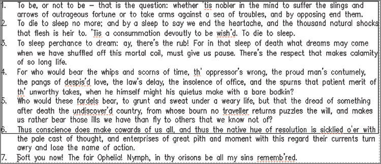
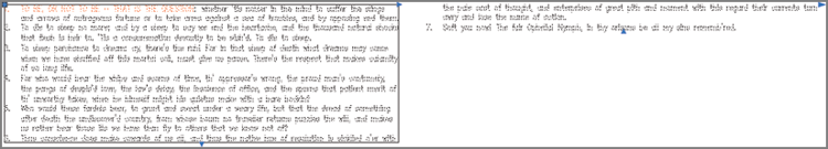
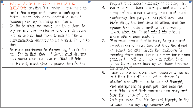
7. Drag the cursor from the end to the beginning of the block of text, and highlight all the text. Open the Bullets And Numbering menu, and choose Numbered from the list. The number 1 appears at the start of the text. Click strategic points in the text, and press Enter to separate the paragraph into the numbered notes shown in
Figure 10-11. Don’t worry if the text extends below the lower edge of the rectangle (it should).
If you exit the text editor, reactivate it by double-clicking the text block. Click within a block of text you are creating or editing to place the cursor at that location. Double-click to select an entire word. Triple-click to select an entire paragraph.
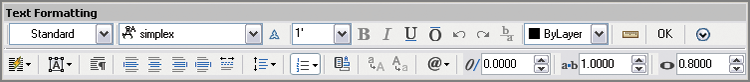
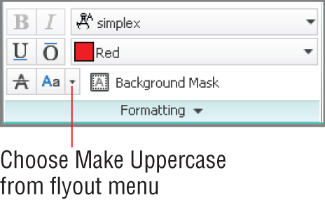
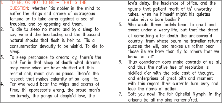
8. Click within the block of text to deselect all text. Drag out a selection that includes the phrase “To be or not to be – that is the question.” Open the Text Editor Color Gallery drop-down in the Formatting panel and select Red. Click the Make Uppercase button in the same panel (see
Figure 10-12).
9. Click anywhere outside the block of text on the drawing canvas to end the MTEXT command.
You can format selected letters or words independently with the
MTEXT or
MTEDIT command.
10. Save your work as Ch10-F.dwg or Ch10-F-metric.dwg.
Editing Text
Editing text can mean many different things, from changing content (the words) and text object properties, to creating multiple columns of text. You would be very frustrated indeed if you couldn’t correct typographical errors, because everyone seems to make them. Fortunately, editing text is as simple as double-clicking, highlighting the text in question, and retyping. It is also easy to create multiple columns in AutoCAD by dragging a grip. Creating columns of text can help you fit the required words into the space available on your drawings.
Editing Content and Properties
Editing text content is as simple as double-clicking existing text and typing something new. Editing text properties requires you to use the Quick Properties palette or the Properties panel. In the following steps, you will edit both content and properties:
1. If the file is not already open, go to the book’s web page, browse to Chapter 10, get the file Ch10-F.dwg or Ch10-F-metric.dwg, and open it.
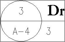
2. Double-click the text in the lower semicircle of the drawing title symbol to invoke the
DDEDIT command. The number 3 is highlighted. Type
A-4, click outside the editing window on the drawing canvas, and press Esc to stop editing. The bubble now references the hypothetical drawing 3 on sheet A-4 (see
Figure 10-13).
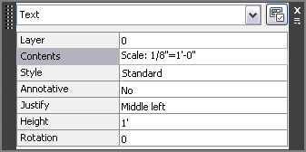
3. Toggle on Quick Properties on the status bar, and select the 3 under the text Drawing Title. In the Quick Properties window that appears, change Justify to Middle Left and type
Scale:1/8″ = 1′-0″ (or
Scale: 1:20) in the Contents text box (see
Figure 10-14).
In AutoCAD 2014, the last justification setting used for single-line text is maintained as the default for the creation of new text.
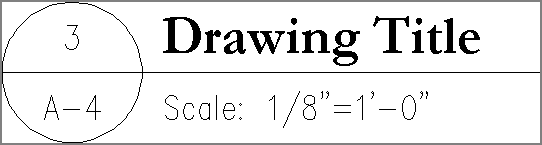
4. Press Enter to update the selected object. Press Esc to deselect. Toggle off Quick Properties.
Figure 10-15 shows the result.
5. Save your work as Ch10-G.dwg or Ch10-G-metric.dwg.
Working with Columns
You can create multiple columns easily with any multiline text object. This feature is perfect if the text you have written doesn’t fit into the space between the drawing and its title block on a typical drawing. Creating multiple columns gives you more layout options, allowing you to find the best fit for paragraphs of text within the space available. In the following steps, you will move object grips to create and size two columns:
1. If the file is not already open, go to the book’s web page, browse to Chapter 10, get the file Ch10-G.dwg or Ch10-G-metric.dwg, and open it.
2. Click once on the numbered Hamlet text to select it and reveal its grips. Click the Column Height (bottom) grip, move it upward, and click again, automatically creating two columns, as shown in
Figure 10-16.
3. Click the Column Width (middle) grip, and move it to the left to reduce the size of both columns simultaneously. Click to set its new position. Click and move the right grip until it reaches the right edge of the rectangle, and then click to set its new position (see
Figure 10-17).
4. The first column is too short compared to the right column. Move the Column Height (bottom) grip down until the text in both columns is roughly equalized. Press Esc to deselect the text. Select the rectangle, and press the Delete key.
Figure 10-18 shows the result.
5. Save your work as Ch10-H.dwg or Ch10-H-metric.dwg.
The Essentials and Beyond
In this chapter, you learned how to work with text. You created text styles, wrote and justified single lines of text, and imported multiple paragraphs of text. In addition, you edited and styled multiline text and learned to control its appearance. You should now be able to express yourself in written form within AutoCAD, and thus convey your design intent both graphically and literally.
Additional Exercise
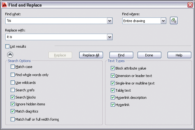
Explore the FIND command on your own. Use it not only to find but also to replace specific words within any of the text in the drawing, its blocks, attributes, dimensions, tables, and/or Xrefs. You can confine a find and replace operation specifically using search options such as Match Case, Search Xrefs, search within Dimension Or Leader Text, and many others. There is an arrow in the lower-left corner of the Find And Replace dialog box that you click to expand the dialog box and thus access all the search options and searchable text types. The following graphic shows the expanded options.