
Code: The Nitty-Gritty Details
Here's another chicken-and-egg situation: We only want to get to know the Android APIs that are relevant for game programming. However, we still don't know how to actually program a game. We have an idea of how to design one, but transforming it into an executable is still voodoo magic to us. In the following subsections, we want to give you an overview of what elements usually make up a game. We'll look at some pseudocode for interfaces that we'll later implement with what Android offers. Interfaces are awesome for two reasons: they allow us to concentrate on the semantics without needing to know the implementation details, and they allow us to exchange the implementation later (for example, instead of using 2D CPU rendering, we could exploit OpenGL ES to display Mr. Nom on the screen).
Every game needs a basic framework that abstracts away and eases the pain of communicating with the underlying operating system. Usually this is split up into modules, as follows:
Window management: This is responsible for creating a window and coping with things like closing the window or pausing/resuming the application in Android.
Input: This is related to the window management module, and it keeps track of user input (that is, touch events, keystrokes, periphery, and accelerometer readings).
File I/O: This allows us to get the bytes of our assets into our program from disk.
Graphics: This is probably the most complex module besides the actual game. It is responsible for loading graphics and drawing them on the screen.
Audio: This module is responsible for loading and playing everything that will hit our ears.
Game framework: This ties all the above together and provides an easy-to-use base for writing our games.
Each of these modules is composed of one or more interfaces. Each interface will have at least one concrete implementation that applies the semantics of the interface based on what the underlying platform (in our case Android) provides.
NOTE: Yes, we deliberately left out networking from the preceding list. We will not implement multiplayer games in this book. That is a rather advanced topic, depending on the type of game. If you are interested in this topic, you can find a range of tutorials on the Web. (www.gamedev.net is a good place to start.)
In the following discussion, we will be as platform-agnostic as possible. The concepts are the same on all platforms.
Application and Window Management
A game is just like any other computer program that has a UI. It is contained in some sort of window (if the underlying operating system's UI paradigm is window based, which is the case for all mainstream operating systems). The window serves as a container, and we basically think of it as a canvas from which we draw our game content.
Most operating systems allow the user to interact with the window in a special way, besides touching the client area or pressing a key. On desktop systems, you can usually drag the window around, resize it, or minimize it to some sort of taskbar. In Android, resizing is replaced with accommodating an orientation change, and minimizing is similar to putting the application in the background, via a press of the home button or as a reaction to an incoming call.
The application and window management module is also responsible for actually setting up the window and making sure it is filled by a single UI component to which we can later render and that receives input from the user in the form of touching or pressing keys. That UI component might be rendered via the CPU or it can be hardware accelerated, as is the case with OpenGL ES.
The application and window management module does not have a concrete set of interfaces. We'll merge it with the game framework later on. The things we have to remember are the application states and window events that we have to manage:
Create: Called once when the window (and thus the application) is started up.
Pause: Called when the application is paused by some mechanism.
Resume: Called when the application is resumed and the window is again in the foreground.
NOTE: Some Android aficionados might roll their eyes at this point. Why use only a single window (activity in Android speak)? Why not use more than one UI widget for the game—say, for implementing complex UIs that our game might need? The main reason is that we want complete control over the look and feel of our game. It also allows us to focus on Android game programming instead of Android UI programming, a topic for which better books exist—for example, Mark Murphy's excellent Beginning Android 2 (Apress, 2010).
Input
The user will surely want to interact with our game in some way. That's where the input module comes in. On most operating systems, input events such as touching the screen or pressing a key are dispatched to the currently-focused window. The window will then further dispatch the event to the UI component that has the focus. The dispatching process is usually transparent to us; our only concern is getting the events from the focused UI component. The UI APIs of the operating system provide a mechanism to hook into the event-dispatching system so that we can easily register and record the events. This hooking into and recording of events is the main task of the input module.
What can we do with the recorded information? There are two modi operandi:
Polling: With polling, we only check the current state of the input devices. Any states between the current check and the last check will be lost. This way of input handling is suitable for checking things like whether a user touches a specific button, for example. It is not suitable for tracking text input, as the order of key events is lost.
Event-based handling: This gives us a full chronological history of the events that have occurred since we last checked. It is a suitable mechanism to perform text input or any other task that relies on the order of events. It's also useful to detect when a finger first touched the screen or when the finger was lifted.
What input devices do we want to handle? On Android, we have three main input methods: touchscreen, keyboard/trackball, and accelerometer. The first two are suitable for both polling and event-based handling. The accelerometer is usually just polled. The touchscreen can generate three events:
Touch down: This happens when a finger is touched to the screen.
Touch drag: This occurs when a finger is dragged across the screen. Before a drag, there's always a down event.
Touch up: This happens when a finger is lifted from the screen.
Each touch event has additional information: the position relative to the UI component origin and a pointer index used in multitouch environments to identify and track separate fingers.
The keyboard can generate two types of events:
Key down: This happens when a key is pressed down.
Key up: This happens when a key is lifted. This event is always preceded by a key-down event.
Key events also carry additional information. Key-down events store the pressed key's code. Key-up events store the key's code and an actual Unicode character. There's a difference between a key's code and the Unicode character generated by a key-up event. In the latter case, the state of other keys is also taken into account, such as the Shift key. This way, we can get uppercase and lowercase letters in a key-up event, for example. With a key-down event, we only know that a certain key was pressed; we have no information on what character that keypress would actually generate.
Developers seeking to use custom USB hardware including joysticks, analog controllers, special keyboards, touchpads, or other Android supported peripherals can do this by utilizing the android.hardware.usb package APIs, which were introduced in API level 12 (Android 3.1) and also backported to Android 2.3.4 via the package com.android.future.usb. The USB APIs allow for an Android device to operate in either host mode, which allows for periphery to be attached to and used by the Android device, or accessory mode, which allows for the device to act as an accessory to another USB host. These APIs aren't quite beginner material, as the device access is very low level, offering data-streaming IO to the USB accessory, but it's important to note that the functionality is indeed there. If your game design revolves around a specific USB accessory, you will certainly want to develop a communication module for the accessory and prototype using it.
Finally, there's the accelerometer. It's important to understand that while nearly all handsets and tablets have accelerometers as standard hardware, many new devices, including set top boxes, may not have an accelerometer, so always plan on having multiple modes of input!
To use the accelerometer, we will always poll the accelerometer's state. The accelerometer reports the acceleration exerted by the gravity of our planet on one of three axes of the accelerometer. The axes are called x, y, and z. Figure 3–20 depicts each axis's orientation. The acceleration on each axis is expressed in meters per second squared (m/s2). From physics class, we know that an object will accelerate at roughly 9.8 m/s2 when in free fall on planet Earth. Other planets have a different gravity, so the acceleration constant is also different. For the sake of simplicity, we'll only deal with planet Earth here. When an axis points away from the center of the Earth, the maximum acceleration is applied to it. If an axis points toward the center of the Earth, we get a negative maximum acceleration. If you hold your phone upright in portrait mode, then the y-axis will report an acceleration of 9.8 m/s2, for example. In Figure 3–20, the z-axis would report an acceleration of 9.8 m/s2, and the x- and y-axes would report and acceleration of zero.
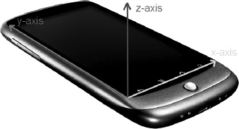
Figure 3–20. The accelerometer axes on an Android phone. The z-axis points out of the phone.
Now, let's define an interface that gives us polling access to the touchscreen, the keyboard, and the accelerometer and that also gives us event-based access to the touchscreen and keyboard (see Listing 3–1).
Listing 3–1. The Input Interface and the KeyEvent and TouchEvent Classes
package com.badlogic.androidgames.framework;


import java.util.List;


public interface Input {

    public static class KeyEvent {

        public static final int KEY_DOWN = 0;

        public static final int KEY_UP = 1;


        public int type;

        public int keyCode;

        public char keyChar;

    }


    public static class TouchEvent {

        public static final int TOUCH_DOWN = 0;

        public static final int TOUCH_UP = 1;

        public static final int TOUCH_DRAGGED = 2;


        public int type;

        public int x, y;

        public int pointer;

    }


    public boolean isKeyPressed(int keyCode);


    public boolean isTouchDown(int pointer);


    public int getTouchX(int pointer);


    public int getTouchY(int pointer);


    public float getAccelX();


    public float getAccelY();
    public float getAccelZ();


    public List<KeyEvent> getKeyEvents();


    public List<TouchEvent> getTouchEvents();

}
Our definition is started off by two classes, KeyEvent and TouchEvent. The KeyEvent class defines constants that encode a KeyEvent's type; the TouchEvent class does the same. A KeyEvent instance records its type, the key's code, and its Unicode character in case the event's type is KEY_UP.
The TouchEvent code is similar, and it holds the TouchEvent's type, the position of the finger relative to the UI component's origin, and the pointer ID that was given to the finger by the touchscreen driver. The pointer ID for a finger will stay the same for as long as that finger is on the screen. If two fingers are down and finger 0 is lifted, then finger 1 keeps its ID for as long as it is touching the screen. A new finger will get the first free ID, which would be 0 in this example. Pointer IDs are often assigned sequentially, but it is not guaranteed to happen that way. For example, a Sony Xperia Play uses 15 IDs and assigns them to touches in a round-robin manner. Do not ever make assumptions in your code about the ID of a new pointer—you can only read the ID of a pointer using the index and reference it until the pointer has been lifted.
Next are the polling methods of the Input interface, which should be pretty self-explanatory. Input.isKeyPressed() takes a keyCode and returns whether the corresponding key is currently pressed or not. Input.isTouchDown(), Input.getTouchX(), and Input.getTouchY() return whether a given pointer is down, as well as its current x- and y-coordinates. Note that the coordinates will be undefined if the corresponding pointer is not actually touching the screen.
Input.getAccelX(), Input.getAccelY(), and Input.getAccelZ() return the respective acceleration values of each accelerometer axis.
The last two methods are used for event-based handling. They return the KeyEvent and TouchEvent instances that got recorded since the last time we called these methods. The events are ordered according to when they occurred, with the newest event being at the end of the list.
With this simple interface and these helper classes, we have all our input needs covered. Let's move on to handling files.
NOTE: While mutable classes with public members are an abomination, we can get away with them in this case for two reasons: Dalvik is still slow when calling methods (getters in this case), and the mutability of the event classes does not have an impact on the inner workings of an Input implementation. Just take note that this is bad style in general, but that we will resort to this shortcut every once in a while for performance reasons.
File I/O
Reading and writing files is quite essential for our game development endeavor. Given that we are in Java land, we are mostly concerned with creating InputStream and OutputStream instances, the standard Java mechanisms for reading and writing data from and to a specific file. In our case, we are mostly concerned with reading files that we package with our game, such as level files, images, and audio files. Writing files is something we'll do a lot less often. Usually, we only write files if we want to maintain high-scores or game settings, or save a game state so that users can pick up from where they left off.
We want the easiest possible file-accessing mechanism. Listing 3–2 shows our proposal for a simple interface.
Listing 3–2. The File I/O Interface
package com.badlogic.androidgames.framework;


import java.io.IOException;

import java.io.InputStream;

import java.io.OutputStream;


public interface FileIO {

    public InputStream readAsset(String fileName) throws IOException;


    public InputStream readFile(String fileName) throws IOException;


    public OutputStream writeFile(String fileName) throws IOException;

}
That's rather lean and mean. We just specify a filename and get a stream in return. As we usually do in Java, we will throw an IOException in case something goes wrong. Where we read and write files from and to will depend on the implementation, of course. Assets will be read from our application's APK file, and files will be read from and written to on the SD card (also known as external storage).
The returned InputStreams and OutputStreams are plain-old Java streams. Of course, we have to close them once we are finished using them.
Audio
While audio programming is a rather complex topic, we can get away with a very simple abstraction. We will not do any advanced audio processing; we'll just play back sound effects and music that we load from files, much like we'll load bitmaps in the graphics module.
Before we dive into our module interfaces, though, let's stop for a moment and get some idea of what sound actually is and how it is represented digitally.
Sound is usually modeled as a set of waves that travel in a medium such as air or water. The wave is not an actual physical object, but is the movement of the molecules within the medium. Think of a little pond into which you throw a stone. When the stone hits the pond's surface, it will push away a lot of water molecules within the pond, and those pushed-away molecules will transfer their energy to their neighbors, which will start to move and push as well. Eventually, you will see circular waves emerge from where the stone hit the pond.
Something similar happens when sound is created. Instead of a circular movement, you get spherical movement, though. As you may know from the highly scientific experiments you may have carried out in your childhood, water waves can interact with each other; they can cancel each other out or reinforce each other. The same is true for sound waves. All sound waves in an environment combine to form the tones and melodies you hear when you listen to music. The volume of a sound is dictated by how much energy the moving and pushing molecules exert on their neighbors and eventually on your ear.
Recording and Playback
The principle of recording and playing back audio is actually pretty simple in theory. For recording, we keep track of the point in time when certain amounts of pressure were exerted on an area in space by the molecules that form the sound waves. Playing back these data is a mere matter of getting the air molecules surrounding the speaker to swing and move like they did when we recorded them.
In practice, it is of course a little more complex. Audio is usually recorded in one of two ways: in analog or digitally. In both cases, the sound waves are recorded with some sort of microphone, which usually consists of a membrane that translates the pushing from the molecules to some sort of signal. How this signal is processed and stored is what makes the difference between analog and digital recording. We are working digitally, so let's just have a look at that case.
Recording audio digitally means that the state of the microphone membrane is measured and stored at discrete time steps. Depending on the pushing by the surrounding molecules, the membrane can be pushed inward or outward with regard to a neutral state. This process is called sampling, as we take membrane state samples at discrete points in time. The number of samples we take per time unit is called the sampling rate. Usually the time unit is given in seconds, and the unit is called Hertz (Hz). The more samples per second, the higher the quality of the audio. CDs play back at a sampling rate of 44,100 Hz, or 44.1 KHz. Lower sampling rates are found, for example, when transferring voice over the telephone line (8 KHz is common in this case).
The sampling rate is only one attribute responsible for a recording's quality. The way we store each membrane state sample also plays a role, and it is also subject to digitalization. Let's recall what the membrane state actually is: it's the distance of the membrane from its neutral state. Since it makes a difference whether the membrane is pushed inward or outward, we record the signed distance. Hence, the membrane state at a specific time step is a single negative or positive number. We can store this signed number in a variety of ways: as a signed 8-, 16-, or 32-bit integer, as a 32-bit float, or even as a 64-bit float. Every data type has limited precision. An 8-bit signed integer can store 127 positive and 128 negative distance values. A 32-bit integer provides a lot more resolution. When stored as a float, the membrane state is usually normalized to a range between –1 and 1. The maximum positive and minimum negative values represent the farthest distance the membrane can have from its neutral state. The membrane state is also called the amplitude. It represents the loudness of the sound that hits it.
With a single microphone, we can only record mono sound, which loses all spatial information. With two microphones, we can measure sound at different locations in space, and thus get so-called stereo sound. You might achieve stereo sound, for example, by placing one microphone to the left and another to the right of an object emitting sound. When the sound is played back simultaneously through two speakers, we can reasonably reproduce the spatial component of the audio. But this also means that we need to store twice the number of samples when storing stereo audio.
The playback is a simple matter in the end. Once we have our audio samples in digital form and with a specific sampling rate and data type, we can throw those data at our audio processing unit, which will transform the information into a signal for an attached speaker. The speaker interprets this signal and translates it into the vibration of a membrane, which in turn will cause the surrounding air molecules to move and produce sound waves. It's exactly what is done for recording, only reversed!
Audio Quality and Compression
Wow, lots of theory. Why do we care? If you paid attention, you can now tell whether an audio file is of high quality or not depending on the sampling rate and the data type used to store each sample. The higher the sampling rate and the higher the data type precision, the better the quality of the audio. However, that also means that we need more storage room for our audio signal.
Imagine that we record the same sound with a length of 60 seconds, but we record it twice: once at a sampling rate of 8 KHz at 8 bits per sample, and once at a sampling rate of 44 KHz at 16-bit precision. How much memory would we need to store each sound? In the first case, we need 1byte per sample. Multiply this by the sampling rate of 8,000 Hz, and we need 8,000 bytes per second. For our full 60 seconds of audio recording, that's 480,000 bytes, or roughly half a megabyte (MB). Our higher-quality recording needs quite a bit more memory: 2 bytes per sample, and 2 times 44,000 bytes per second. That's 88,000 bytes per second. Multiply this by 60 seconds, and we arrive at 5,280,000 bytes, or a little over 5 MB. Your usual 3–minute pop song would take up over 15 MB at that quality, and that's only a mono recording. For a stereo recording, you'd need twice that amount of memory. Quite a lot of bytes for a silly song!
Many smart people have come up with ways to reduce the number of bytes needed for an audio recording. They've invented rather complex psychoacoustic compression algorithms that analyze an uncompressed audio recording and output a smaller, compressed version. The compression is usually lossy, meaning that some minor parts of the original audio are omitted. When you playback MP3s or OGGs, you are actually listening to compressed lossy audio. So, using formats such as MP3 or OGG will help us reduce the amount of space needed to store our audio on disk.
What about playing back the audio from compressed files? While dedicated decoding hardware exists for various compressed audio formats, common audio hardware can often only cope with uncompressed samples. Before actually feeding the audio card with samples, we have to first read them in and decompress them. We can do this once and store all of the uncompressed audio samples in memory, or only stream in partitions from the audio file as needed.
In Practice
You have seen that even 3–minute songs can take up a lot of memory. When we play back our game's music, we will therefore stream the audio samples in on the fly instead of preloading all audio samples to memory. Usually, we only have a single music stream playing, so we only have to access the disk once.
For short sound effects, such as explosions or gunshots, the situation is a little different. We often want to play a sound effect multiple times simultaneously. Streaming the audio samples from disk for each instance of the sound effect is not a good idea. We are lucky, though, as short sounds do not take up a lot of memory. We will therefore read all samples of a sound effect into memory, from where we can directly and simultaneously play them back.
We have the following requirements:
- We need a way to load audio files for streaming playback and for playback from memory.
- We need a way to control the playback of streamed audio.
- We need a way to control the playback of fully loaded audio.
This directly translates into the Audio, Music, and Sound interfaces (shown in Listing 3–3 through 3–5, respectively).
Listing 3–3. The Audio Interface
package com.badlogic.androidgames.framework;


public interface Audio {

    public Music newMusic(String filename);


    public Sound newSound(String filename);

}
The Audio interface is our way to create new Music and Sound instances. A Music instance represents a streamed audio file. A Sound instance represents a short sound effect that we keep entirely in memory. The methods Audio.newMusic() and Audio.newSound() both take a filename as an argument and throw an IOException in case the loading process fails (for example, when the specified file does not exist or is corrupt). The filenames refer to asset files in our application's APK file.
Listing 3–4. The Music Interface
package com.badlogic.androidgames.framework;


public interface Music {

    public void play();


    public void stop();


    public void pause();


    public void setLooping(boolean looping);


    public void setVolume(float volume);


    public boolean isPlaying();


    public boolean isStopped();


    public boolean isLooping();


    public void dispose();

}
The Music interface is a little bit more involved. It features methods to start playing the music stream, pausing and stopping it, and setting it to loop playback, which means it will automatically start from the beginning when it reaches the end of the audio file. Additionally, we can set the volume as a float in the range of 0 (silent) to 1 (maximum volume). A couple of getter methods are also available that allow us to poll the current state of the Music instance. Once we no longer need the Music instance, we have to dispose of it. This will close any system resources, such as the file from which the audio was streamed.
Listing 3–5. The Sound Interface
package com.badlogic.androidgames.framework;


public interface Sound {

    public void play(float volume);

,,,

    public void dispose();

}
The Sound interface is simpler. All we need to do is call its play() method, which again takes a float parameter to specify the volume. We can call the play() method anytime we want (for example, when Mr. Nom eats an ink stain). Once we no longer need the Sound instance, we have to dispose of it to free up the memory that the samples use, as well as other system resources that are potentially associated.
NOTE: While we covered a lot of ground in this chapter, there's a lot more to learn about audio programming. We simplified some things to keep this section short and sweet. Usually you wouldn't specify the audio volume linearly, for example. In our context, it's OK to overlook this little detail. Just be aware that there's more to it!
Graphics
The last module at the core of our game framework is the graphics module. As you might have guessed, it will be responsible for drawing images (also known as bitmaps) to our screen. This may sound easy, but if you want high-performance graphics, you have to know at least the basics of graphics programming. Let's start with the basics of 2D graphics.
The first question we need to ask goes like this: how on Earth are the images output to my display? The answer is rather involved, and we do not necessarily need to know all the details. We'll just quickly review what's happening inside our computer and the display.
Of Rasters, Pixels, and Framebuffers
Today's displays are raster based. A raster is a two-dimensional grid of so-called picture elements. You might know them as pixels, and we'll refer to them as such in the subsequent text. The raster grid has a limited width and height, which we usually express as the number of pixels per row and per column. If you feel brave, you can turn on your computer and try to make out individual pixels on your display. Note that we're not responsible for any damage that does to your eyes, though.
A pixel has two attributes: a position within the grid and a color. A pixel's position is given as two-dimensional coordinates within a discrete coordinate system. Discrete means that a coordinate is always at an integer position. Coordinates are defined within a Euclidean coordinate system imposed on the grid. The origin of the coordinate system is the top-left corner of the grid. The positive x-axis points to the right and the y-axis points downward. The last item is what confuses people the most. We'll come back to it in a minute; there's a simple reason why this is the case.
Ignoring the silly y-axis, we can see that, due to the discrete nature of our coordinates, the origin is coincident with the top-left pixel in the grid, which is located at (0,0). The pixel to the right of the origin pixel is located at (1,0), the pixel beneath the origin pixel is at (0,1), and so on (see the left side of Figure 3–21). The display's raster grid is finite, so there's a limited number of meaningful coordinates. Negative coordinates are outside the screen. Coordinates greater than or equal to the width or height of the raster are also outside the screen. Note that the biggest x-coordinate is the raster's width minus 1, and the biggest y-coordinate is the raster's height minus 1. That's due to the origin being coincident with the top-left pixel. Off-by-one errors are a common source of frustration in graphics programming.
The display receives a constant stream of information from the graphics processor. It encodes the color of each pixel in the display's raster, as specified by the program or operating system in control of drawing to the screen. The display will refresh its state a few dozen times per second. The exact rate is called the refresh rate. It is expressed in Hertz. Liquid crystal displays (LCDs) usually have a refresh rate of 60 Hz per second; cathode ray tube (CRT) monitors and plasma monitors often have higher refresh rates.
The graphics processor has access to a special memory area known as video memory, or VRAM. Within VRAM there's a reserved area for storing each pixel to be displayed on the screen. This area is usually called the framebuffer. A complete screen image is therefore called a frame. For each pixel in the display's raster grid, there's a corresponding memory address in the framebuffer that holds the pixel's color. When we want to change what's displayed on the screen, we simply change the color values of the pixels in that memory area in VRAM.
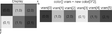
Figure 3–21. Display raster grid and VRAM, oversimplified
Now it's time to explain why the y-axis in the display's coordinate system is pointing downward. Memory, be it VRAM or normal RAM, is linear and one dimensional. Think of it as a one-dimensional array. So how do we map the two-dimensional pixel coordinates to one-dimensional memory addresses? Figure 3–21 shows a rather small display raster grid of three-by-two pixels, as well as its representation in VRAM. (We assume VRAM only consists of the framebuffer memory.)From this, we can easily derive the following formula to calculate the memory address of a pixel at (x,y):
int address = x + y * rasterWidth;
We can also go the other way around, from an address to the x- and y-coordinates of a pixel:
int x = address % rasterWidth;

int y = address / rasterWidth;
So, the y-axis is pointing downward because of the memory layout of the pixel colors in VRAM. This is actually a sort of legacy inherited from the early days of computer graphics. Monitors would update the color of each pixel on the screen, starting at the top-left corner, moving to the right, and tracing back to the left on the next line, until they reached the bottom of the screen. It was convenient to have the VRAM contents laid out in a manner that eased the transfer of the color information to the monitor.
NOTE: If we had full access to the framebuffer, we could use the preceding equation to write a full-fledged graphics library to draw pixels, lines, rectangles, images loaded to memory, and so on. Modern operating systems do not grant us direct access to the framebuffer for various reasons. Instead, we usually draw to a memory area that is then copied to the actual framebuffer by the operating system. The general concepts hold true in this case as well, though! If you are interested in how to do these low-level things efficiently, search the Web for a guy called Bresenham and his line-and-circle-drawing algorithms.
Vsync and Double-Buffering
Now, if you remember the paragraph about refresh rates, you might have noticed that those rates seem rather low and that we might be able to write to the framebuffer faster than the display will refresh. That can happen. Even worse, we don't know when the display is grabbing its latest frame copy from VRAM, which could be a problem if we're in the middle of drawing something. In this case, the display will then show parts of the old framebuffer content and parts of the new state, which is an undesirable situation. You can see that effect in many PC games where it expresses itself as tearing (in which the screen simultaneously shows parts of the last frame and parts of the new frame).
The first part of the solution to this problem is called double-buffering. Instead of having a single framebuffer, the graphics processing unit (GPU) actually manages two of them: a front buffer and a back buffer. The front buffer, from which the pixel colors will be fetched, is available to the display, and the back buffer is available to draw our next frame while the display happily feeds off the front buffer. When we finish drawing our current frame, we tell the GPU to switch the two buffers with each other, which usually means just swapping the address of the front and back buffer. In graphics programming literature, and in API documentation, you may find the terms page flip and buffer swap, which refer to this process.
Double-buffering alone does not solve the problem entirely, though: the swap can still happen while the screen is in the middle of refreshing its content. That's where vertical synchronization (also known as vsync) comes into play. When we call the buffer swap method, the GPU will block until the display signals that it has finished its current refresh. If that happens, the GPU can safely swap the buffer addresses and all will be well.
Luckily, we barely need to care about these pesky details nowadays. VRAM and the details of double-buffering and vsyncing are securely hidden from us so that we cannot wreak havoc with them. Instead, we are provided with a set of APIs that usually limit us to manipulating the contents of our application window. Some of these APIs, such as OpenGL ES, expose hardware acceleration, which basically does nothing more than manipulate VRAM with specialized circuits on the graphics chip. See, it's not magic! The reason you should be aware of the inner workings, at least at a high level, is that it allows you to understand the performance characteristics of your application. When vsync is enabled, you can never go above the refresh rate of your screen, which might be puzzling if all you're doing is drawing a single pixel.
When we render with non-hardware-accelerated APIs, we don't directly deal with the display itself. Instead, we draw to one of the UI components in our window. In our case, we deal with a single UI component that is stretched over the whole window. Our coordinate system will therefore not stretch over the entire screen, but only our UI component. The UI component effectively becomes our display, with its own virtual framebuffer. The operating system will then manage compositing the contents of all the visible windows and ensuring that their contents are correctly transferred to the regions that they cover in the real framebuffer.
What Is Color?
You will notice that we have conveniently ignored colors so far. We made up a type called color in Figure 3–21 and pretended all is well. Let's see what color really is.
Physically, color is the reaction of your retina and visual cortex to electromagnetic waves. Such a wave is characterized by its wavelength and its intensity. We can see waves with a wavelength between roughly 400 and 700 nm. That sub-band of the electromagnetic spectrum is also known as the visible light spectrum. A rainbow shows all the colors of this visible light spectrum, going from violet to blue to green to yellow, followed by orange and ending at red. All a monitor does is emit specific electromagnetic waves for each pixel, which we experience as the color of each pixel. Different types of displays use different methods to achieve that goal. A simplified version of this process goes like this: every pixel on the screen is made up of three different fluorescent particles that will emit light with one of the colors red, green, or blue. When the display refreshes, each pixel's fluorescent particles will emit light by some means (for example, in the case of CRT displays, the pixel's particles get hit by a bunch of electrons). For each particle, the display can control how much light it emits. For example, if a pixel is entirely red, only the red particle will be hit with electrons at full intensity. If we want colors other than the three base colors, we can achieve that by mixing the base colors. Mixing is done by varying the intensity with which each particle emits its color. The electromagnetic waves will overlay each other on the way to our retina. Our brain interprets this mix as a specific color. A color can thus be specified by a mix of intensities of the base colors red, green, and blue.
Color Models
What we just discussed is called a color model, specifically the RGB color model. RGB stands for red, green, and blue, of course. There are many more color models we could use, such as YUV and CMYK. In most graphics programming APIs, the RGB color model is pretty much the standard, though, so we'll only discuss that here.
The RGB color model is called an additive color model, due to the fact that the final color is derived via mixing the additive primary colors red, green, and blue. You've probably experimented with mixing primary colors in school. Figure 3–22 shows you some examples for RGB color mixing to refresh your memory a little bit.
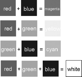
Figure 3–22. Having fun with mixing the primary colors red, green, and blue
We can, of course, generate a lot more colors than the ones shown in Figure 3–22 by varying the intensity of the red, green, and blue components. Each component can have an intensity value between 0 and some maximum value (say, 1). If we interpret each color component as a value on one of the three axes of a three-dimensional Euclidian space, we can plot a so-called color cube, as depicted in Figure 3–23. There are a lot more colors available to us if we vary the intensity of each component. A color is given as a triplet (red, green, blue) where each component is in the range between 0.0 and 1.0. 0.0 means no intensity for that color, and 1.0 means full intensity. The color black is at the origin (0,0,0), and the color white is at (1,1,1).
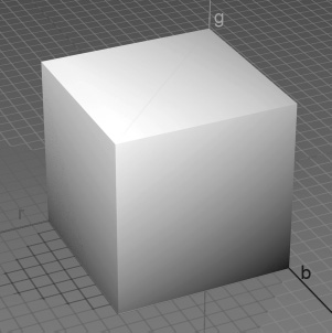
Figure 3–23. The mighty RGB color cube
How can we encode an RGB color triplet in computer memory? First, we have to define what data type we want to use for the color components. We could use floating-point numbers and specify the valid range as being between 0.0 and 1.0. This would give us quite some resolution for each component and would make a lot of different colors available to us. Sadly, this approach uses up a lot of space (3 times 4 or 8 bytes per pixel, depending on whether we use 32-bit or 64-bit floats).
We can do better—at the expense of losing a few colors—which is totally OK, since displays usually have a limited range of colors that they can emit. Instead of using a float for each component, we can use an unsigned integer. Now, if we use a 32-bit integer for each component, we haven't gained anything. Instead, we use an unsigned byte for each component. The intensity for each component then ranges from 0 to 255. For 1 pixel, we thus need 3 bytes, or 24 bits. That's 2 to the power of 24 (16,777,216) different colors. I'd say that's enough for our needs.
Can we get that down even more? Yes, we can. We can pack each component into a single 16-bit word, so each pixel needs 2 bytes of storage. Red uses 5 bits, green uses 6 bits, and blue uses the rest of 5 bits. The reason green gets 6 bits is that our eyes can see more shades of green than of red or blue. All bits together make 2 to the power of 16 (65,536) different colors that we can encode. Figure 3–24 shows how a color is encoded with the three encodings described previously.
Figure 3–24. Color encodings of a nice shade of pink (which will be gray in the print copy of this book, sorry)
In the case of the float, we could use three 32-bit Java floats. In the 24-bit encoding case, we have a little problem: there's no 24-bit integer type in Java, so we could either store each component in a single byte or use a 32-bit integer, leaving the upper 8 bits unused. In case of the 16-bit encoding, we can again either use two separate bytes or store the components in a single short value. Note that Java does not have unsigned types. Due to the power of the two's complement, we can safely use signed integer types to store unsigned values.
For both 16- and 24-bit integer encodings, we also need to specify the order in which we store the three components in the short or integer value. Two methods are usually used: RGB and BGR. Figure 3–23 uses RGB encoding. The blue component is in the lowest 5 or 8 bits, the green component uses up the next 6 or 8 bits, and the red component uses the upper 5 or 8 bits. BGR encoding just reverses this order. The green bits stay where they are, and the red and blue bits swap places. We'll use the RGB order throughout this book, as Android's graphics APIs work with that order as well. Let's summarize the color encodings discussed so far:
- A 32-bit float RGB encoding has 12 bytes for each pixel, and intensities that vary between 0.0 and 1.0.
- A 24-bit integer RGB encoding has 3 or 4 bytes for each pixel, and intensities that vary between 0 and 255. The order of the components can be RGB or BGR. This is also known as RGB888 or BGR888 in some circles, where 8 specifies the number of bits per component.
- A 16-bit integer RGB encoding has 2 bytes for each pixel; red and blue have intensities between 0 and 31, and green has intensities between 0 and 63. The order of the components can be RGB or BGR. This is also known as RGB565 or BGR565 in some circles, where 5 and 6 specify the number of bits of the respective component.
The type of encoding we use is also called the color depth. Images we create and store on disk or in memory have a defined color depth, and so do the framebuffers of the actual graphics hardware and the display itself. Today's displays usually have a default color depth of 24bit, and they can be configured to use less in some cases. The framebuffer of the graphics hardware is also rather flexible, and it can use many different color depths. Our own images can, of course, also have any color depth we like.
NOTE: There are a lot more ways to encode per-pixel color information. Apart from RGB colors, we could also have gray scale pixels, which only have a single component. As those are not used a lot, we'll ignore them at this point.
Image Formats and Compression
At some point in our game development process, our artist will provide us with images that were created with graphics software like Gimp, Paint.NET, or Photoshop. These images can be stored in a variety of formats on disk. Why is there a need for these formats in the first place? Can't we just store the raster as a blob of bytes on disk?
Well, we could, but let's check how much memory that would take up. Say that we want the best quality, so we choose to encode our pixels in RGB888at 24bits per pixel. The image would be 1,024 × 1,024 in size. That's 3 MB for a single puny image alone! Using RGB565, we can get that down to roughly 2 MB.
As in the case of audio, there's been a lot of research on how to reduce the memory needed to store an image. As usual, compression algorithms are employed, specifically tailored for the needs of storing images and keeping as much of the original color information as possible. The two most popular formats are JPEG and PNG. JPEG is a lossy format. This means that some of the original information is thrown away in the process of compression. PNG is a lossless format, and it will reproduce an image that's 100 percent true to the original. Lossy formats usually exhibit better compression characteristics and take up less space on disk. We can therefore choose what format to use depending on the disk memory constraints.
Similar to sound effects, we have to decompress an image fully when we load it into memory. So, even if your image is 20KB compressed on disk, you still need the full width times height times color depth storage space in RAM.
Once loaded and decompressed, the image will be available in the form of an array of pixel colors in exactly the same way the framebuffer is laid out in VRAM. The only difference is that the pixels are located in normal RAM, and that the color depth might differ from the framebuffer's color depth. A loaded image also has a coordinate system like the framebuffer, with the origin in its top-left corner, the x-axis pointing to the right, and the y-axis pointing downward.
Once an image is loaded, we can draw it in RAM to the framebuffer simply by transferring the pixel colors from the image to appropriate locations in the framebuffer. We don't do this by hand; instead, we use an API that provides that functionality.
Alpha Compositing and Blending
Before we can start designing our graphics module interfaces, we have to tackle one more thing: image compositing. For the sake of this discussion, assume that we have a framebuffer to which we can render, as well as a bunch of images loaded into RAM that we'll throw at the framebuffer. Figure 3–25 shows a simple background image, as well as Bob, a zombie-slaying ladies' man.
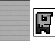
Figure 3–25. A simple background and Bob, master of the universe
To draw Bob's world, we'd first draw the background image to the framebuffer followed by Bob over the background image in the framebuffer. This process is called compositing, as we compose different images into a final image. The order in which we draw images is relevant, as any new draw call will overwrite the current contents in the framebuffer. So, what would be the final output of our compositing? Figure 3–26 shows it to you.

Figure 3–26. Compositing the background and Bob into the framebuffer (not what we wanted)
Ouch, that's not what we wanted. In Figure 3–26, notice that Bob is surrounded by white pixels. When we draw Bob on top of the background to the framebuffer, those white pixels also get drawn, effectively overwriting the background. How can we draw Bob's image so that only Bob's pixels are drawn and the white background pixels are ignored?
Enter alpha blending. Well, in Bob's case it's technically called alpha masking, but that's just a subset of alpha blending. Graphics software usually lets us not only specify the RGB values of a pixel, but also indicate its translucency. Think of it as yet another component of a pixel's color. We can encode it just like we encoded the red, green, and blue components.
We hinted earlier that we could store a 24-bit RGB triplet in a 32-bit integer. There are 8 unused bits in that 32-bit integer that we can grab and in which we can store our alpha value. We can then specify the translucency of a pixel from 0 to 255, where 0 is fully transparent and 255 is opaque. This encoding is known as ARGB8888 or BGRA8888, depending on the order of the components. There are also RGBA8888 and ABGR8888 formats, of course.
In the case of 16-bit encoding, we have a slight problem: all of the bits of our 16-bit short are taken up by the color components. Let's instead imitate the ARGB8888 format and define an ARGB4444 format analogously. That leaves 12 bits for our RGB values in total—4 bits per color component.
We can easily imagine how a rendering method for pixels that's fully translucent or opaque would work. In the first case, we'd just ignore pixels with an alpha component of zero. In the second case, we'd simply overwrite the destination pixel. When a pixel has neither a fully translucent nor fully opaque alpha component, however, things get a tiny bit more complicated.
When talking about blending in a formal way, we have to define a few things:
- Blending has two inputs and one output, each represented as an RGB triplet (C) plus an alpha value (α).
- The two inputs are called source and destination. The source is the pixel from the image we want to draw over the destination image (that is, the framebuffer). The destination is the pixel we are going to overdraw (partially) with our source pixel.
- The output is again a color expressed as an RGB triplet and an alpha value. Usually, we just ignore the alpha value, though. For simplicity we'll do that in this chapter.
- To simplify our math a little bit, we'll represent RGB and alpha values as floats in the range of 0.0 to 1.0.
Equipped with those definitions, we can create so-called blending equations. The simplest equation looks like this:
red = src.red * src.alpha + dst.red * (1 - src.alpha)

blue = src.green * src.alpha + dst.green * (1 - src.alpha)

green = src.blue * src.alpha + dst.blue * (1 - src.alpha)
src and dst are the pixels of the source and destination we want to blend with each other. We blend the two colors component-wise. Note the absence of the destination alpha value in these blending equations. Let's try an example and see what it does:
src = (1, 0.5, 0.5), src.alpha = 0.5, dst = (0, 1, 0)

red = 1 * 0.5 + 0 * (1 - 0.5) = 0.5

blue = 0.5 * 0.5 + 1 * (1 - 0.5) = 0.75

red = 0.5 * 0.5 + 0 * (1 - 0.5) = 0.25
Figure 3–27 illustrates the preceding equation. Our source color is a shade of pink, and the destination color is a shade of green. Both colors contribute equally to the final output color, resulting in a somewhat dirty shade of green or olive.
Figure 3–27. Blending two pixels
Two fine gentlemen named Porter and Duff came up with a slew of blending equations. We will stick with the preceding equation, though, as it covers most of our use cases. Try experimenting with it on paper or in the graphics software of your choice to get a feeling for what blending will do to your composition.
NOTE: Blending is a wide field. If you want to exploit it to its fullest potential, we suggest that you search the Web for Porter and Duff's original work on the subject. For the games we will write, though, the preceding equation is sufficient.
Notice that there are a lot of multiplications involved in the preceding equations (six, to be precise). Multiplications are costly, and we should try to avoid them where possible. In the case of blending, we can get rid of three of those multiplications by pre-multiplying the RGB values of the source pixel color with the source alpha value. Most graphics software supports pre-multiplication of an image's RGB values with the respective alphas. If that is not supported, you can do it at load time in memory. However, when we use a graphics API to draw our image with blending, we have to make sure that we use the correct blending equation. Our image will still contain the alpha values, so the preceding equation would output incorrect results. The source alpha must not be multiplied with the source color. Luckily, all Android graphics APIs allow us to specify fully how we want to blend our images.
In Bob's case, we just set all the white pixels' alpha values to zero in our preferred graphics software program, load the image in ARGB8888 or ARGB4444 format, maybe pre-multiply the alpha, and use a drawing method that does the actual alpha blending with the correct blending equation. The result would look like Figure 3–28.
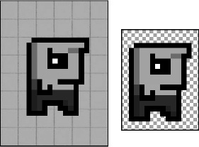
Figure 3–28. Bob blended is on the left, and Bob in Paint.NET.is on the right. The checkerboard illustrates that the alpha of the white background pixels is zero, so the background checkerboard shines through.
NOTE: The JPEG format does not support storage of alpha values per pixel. Use the PNG format in that case.
In Practice
With all of this information, we can finally start to design the interfaces for our graphics module. Let's define the functionality of those interfaces. Note that when we refer to the framebuffer, we actually mean the virtual framebuffer of the UI component to which we draw. We just pretend that we directly draw to the real framebuffer. We'll need to be able to perform the following operations:
- Load images from disk, and store them in memory for drawing them later on.
- Clear the framebuffer with a color so that we can erase what's still there from the last frame.
- Set a pixel in the framebuffer at a specific location to a specific color.
- Draw lines and rectangles to the framebuffer.
- Draw previously loaded images to the framebuffer. We'd like to be able to draw either the complete image or portions of it. We also need to be able to draw images with and without blending.
- Get the dimensions of the framebuffer.
We propose two simple interfaces: Graphics and Pixmap. Let's start with the Graphics interface, shown in Listing 3–6.
Listing 3–6. The Graphics Interface
package com.badlogic.androidgames.framework;


public interface Graphics {

    public static enum PixmapFormat {

        ARGB8888, ARGB4444, RGB565

    }


    public Pixmap newPixmap(String fileName, PixmapFormat format);


    public void clear(int color);


    public void drawPixel(int x, int y, int color);


    public void drawLine(int x, int y, int x2, int y2, int color);


    public void drawRect(int x, int y, int width, int height, int color);


    public void drawPixmap(Pixmap pixmap, int x, int y, int srcX, int srcY,

            int srcWidth, int srcHeight);


    public void drawPixmap(Pixmap pixmap, int x, int y);


    public int getWidth();


    public int getHeight();

}
We start with a public static enum called PixmapFormat. It encodes the different pixel formats we will support. Next, we have the different methods of our Graphics interface:
The Graphics.newPixmap()method will load an image given in either JPEG or PNG format. We specify a desired format for the resultingPixmap, which is a hint for the loading mechanism. The resultingPixmapmight have a different format. We do this so that we can somewhat control the memory footprint of our loaded images (for example, by loading RGB888 or ARGB8888 images as RGB565 or ARGB4444 images). The filename specifies an asset in our application's APK file.- The
Graphics.clear()method clears the complete framebuffer with the givencolor. All colors in our little framework will be specified as 32-bit ARGB8888 values (Pixmaps might of course have a different format). - The
Graphics.drawPixel()method will set the pixel at (x,y) in the framebuffer to the givencolor. Coordinates outside the screen will be ignored. This is called clipping. - The
Graphics.drawLine()method is analogous to theGraphics.drawPixel()method. We specify the start point and endpoint of the line, along with a color. Any portion of the line that is outside the framebuffer's raster will be ignored. - The
Graphics.drawRect()method draws a rectangle to the framebuffer. The (x,y) specifies the position of the rectangle's top-left corner in the framebuffer. The argumentswidthandheightspecify the number of pixels in x and y, and the rectangle will fill starting from (x,y). We fill downward in y. Thecolorargument is the color that is used to fill the rectangle. - The
Graphics.drawPixmap()method draws rectangular portions of aPixmapto the framebuffer. The (x,y) coordinates specify the top-left corner's position of thePixmap's target location in the framebuffer. The argumentssrcXandsrcYspecify the corresponding top-left corner of the rectangular region that is used from thePixmap, given in thePixmap's own coordinate system. Finally,srcWidthandsrcHeightspecify the size of the portion that we take from thePixmap. - Finally, the
Graphics.getWidth()andGraphics.getHeight()methods return the width and height of the framebuffer in pixels.
All of the drawing methods except Graphics.clear() will automatically perform blending for each pixel they touch, as outlined in the previous section. We could disable blending on a case-by-case basis to speed up the drawing somewhat, but that would complicate our implementation. Usually, we can get away with having blending enabled all the time for simple games like Mr. Nom.
The Pixmap interface is given in Listing 3–7.
Listing 3–7. The Pixmap Interface
package com.badlogic.androidgames.framework;


import com.badlogic.androidgames.framework.Graphics.PixmapFormat;


public interface Pixmap {

    public int getWidth();


    public int getHeight();


    public PixmapFormat getFormat();


    public void dispose();

}
We keep it very simple and immutable, as the compositing is done in the framebuffer.
- The
Pixmap.getWidth()andPixmap.getHeight()methods return the width and the height of thePixmapin pixels. - The
Pixmap.getFormat()method returns thePixelFormatthat thePixmapis stored with in RAM. - Finally, there's the
Pixmap.dispose()method.Pixmapinstances use up memory and potentially other system resources. If we no longer need them, we should dispose of them with this method.
With this simple graphics module, we can implement Mr. Nom easily later on. Let's finish this chapter with a discussion of the game framework itself.
The Game Framework
After all the groundwork we've done, we can finally talk about how to implement the game itself. For that, let's identify what tasks have to be performed by our game:
- The game is split up into different screens. Each screen performs the same tasks: evaluating user input, applying the input to the state of the screen, and rendering the scene. Some screens might not need any user input, but transition to another screen after some time has passed (for example, a splash screen).
- The screens need to be managed somehow (that is, we need to keep track of the current screen and have a way to transition to a new screen, which boils down to destroying the old screen and setting the new screen as the current screen).
- The game needs to grant the screens access to the different modules (for graphics, audio, input, and so forth) so that they can load resources, fetch user input, play sounds, render to the framebuffer, and so on.
- As our games will be in real-time (that means things will be moving and updating constantly), we have to make the current screen update its state and render itself as often as possible. We'd normally do that inside a loop called the main loop. The loop will terminate when the user quits the game. A single iteration of this loop is called a frame. The number of frames per second (FPS) that we can compute is called the frame rate.
- Speaking of time, we also need to keep track of the time span that has passed since our last frame. This is used for frame-independent movement, which we'll discuss in a minute.
- The game needs to keep track of the window state (that is, whether it was paused or resumed), and inform the current screen of these events.
- The game framework will deal with setting up the window and creating the UI component we render to and receive input from.
Let's boil this down to some pseudocode, ignoring the window management events like pause and resume for a moment:
createWindowAndUIComponent();


Input input = new Input();

Graphics graphics = new Graphics();

Audio audio = new Audio();

Screen currentScreen = new MainMenu();

Float lastFrameTime = currentTime();


while( !userQuit() ) {

   float deltaTime = currentTime() - lastFrameTime;

   lastFrameTime = currentTime();


   currentScreen.updateState(input, deltaTime);

   currentScreen.present(graphics, audio, deltaTime);

}


cleanupResources();
We start off by creating our game's window and the UI component to which we render and from which we receive input. Next, we instantiate all the modules necessary to do the low-level work. We instantiate our starting screen and make it the current screen, and we record the current time. Then we enter the main loop, which will terminate if the user indicates that he or she wants to quit the game.
Within the game loop, we calculate the so-called delta time. This is the time that has passed since the beginning of the last frame. We then record the time of the beginning of the current frame. The delta time and the current time are usually given in seconds. For the screen, the delta time indicates how much time has passed since it was last updated—information that is needed if we want to do frame-independent movement (which we'll come back to in a minute).
Finally, we simply update the current screen's state and present it to the user. The update depends on the delta time as well as the input state; hence, we provide those to the screen. The presentation consists of rendering the screen's state to the framebuffer, as well as playing back any audio the screen's state demands (that is, due to a shot that was fired in the last update). The presentation method might also need to know how much time has passed since it was last invoked.
When the main loop is terminated, we can clean up and release all resources and close the window.
And that is how virtually every game works at a high level. Process the user input, update the state, present the state to the user, and repeat ad infinitum (or until the user is fed up with our game).
UI applications on modern operating systems do not usually work in real-time. They work with an event-based paradigm, where the operating system informs the application of input events, as well as when to render itself. This is achieved by callbacks that the application registers with the operating system on startup; these are then responsible for processing received event notifications. All of this happens in the so-called UI thread—the main thread of a UI application. It is generally a good idea to return from the callbacks as fast as possible, so we would not want to implement our main loop in one of these.
Instead, we host our game's main loop in a separate thread that we'll spawn when our game is firing up. This means that we have to take some precautions when we want to receive UI thread events, such as input events or window events. But those are details that we'll handle later on, when we implement our game framework for Android. Just remember that we need to synchronize the UI thread and the game's main loop thread at certain points.
The Game and Screen Interfaces
With all of that said, let's try to design a game interface. Here's what an implementation of this interface has to do:
- Set up the window and UI component and hook into callbacks so that we can receive window and input events.
- Start the main loop thread.
- Keep track of the current screen, and tell it to update and present itself in every main loop iteration (aka frame).
- Transfer any window events (for example, pause and resume events) from the UI thread to the main loop thread and pass them on to the current screen so that it can change its state accordingly.
- Grant access to all the modules we developed earlier:
Input,FileIO,Graphics, andAudio.
As game developers, we want to be agnostic about what thread our main loop is running on and whether we need to synchronize with a UI thread or not. We'd just like to implement the different game screens with a little help from the low-level modules and some notifications of window events. We will therefore create a very simple Game interface that hides all this complexity from us, as well as an abstract Screen class that we'll use to implement all of our screens. Listing 3–8 shows the Game interface.
Listing 3–8. The Game Interface
package com.badlogic.androidgames.framework;


public interface Game {

    public Input getInput();


    public FileIO getFileIO();


    public Graphics getGraphics();


    public Audio getAudio();


    public void setScreen(Screen screen);
    public Screen getCurrentScreen();


    public Screen getStartScreen();

}
As expected, a couple of getter methods are available that return the instances of our low-level modules, which the Game implementation will instantiate and track.
The Game.setScreen() method allows us to set the current Screen of the Game. These methods will be implemented once, along with all the internal thread creation, window management, and main loop logic that will constantly ask the current screen to present and update itself.
The Game.getCurrentScreen() method returns the currently active Screen.
We'll use an abstract class called AndroidGame later on to implement the Game interface, which will implement all methods except the Game.getStartScreen() method. This method will be an abstract method. If we create the AndroidGame instance for our actual game, we'll extend it and override the Game.getStartScreen() method, returning an instance to the first screen of our game.
To give you an impression of how easy it will be to setup our game, here's an example (assuming we have already implemented the AndroidGame class):
public class MyAwesomeGame extends AndroidGame {

    public Screen getStartScreen () {

        return new MySuperAwesomeStartScreen(this);

    }

}
That is pretty awesome, isn't it? All we have to do is implement the screen that we want to use to start our game, and the AndroidGame class will do the rest for us. From that point onward, our MySuperAwesomeStartScreen will be asked to update and render itself by the AndroidGame instance in the main loop thread. Note that we pass the MyAwesomeGame instance itself to the constructor of our Screen implementation.
NOTE: If you're wondering what actually instantiates our MyAwesomeGame class, we'll give you a hint: AndroidGame will be derived from Activity, which will be automatically instantiated by the Android operating system when a user starts our game.
The last piece in the puzzle is the abstract class Screen. We make it an abstract class instead of an interface so that we can implement some bookkeeping. This way, we have to write less boilerplate code in the actual implementations of the abstract Screen class. Listing 3–9 shows the abstract Screen class.
Listing 3–9. The Screen Class
package com.badlogic.androidgames.framework;


public abstract class Screen {

    protected final Game game;
    public Screen(Game game) {

        this .game = game;

    }


    public abstract void update(float deltaTime);


    public abstract void present(float deltaTime);


    public abstract void pause();


    public abstract void resume();


    public abstract void dispose();

}
It turns out that the bookkeeping isn't so bad after all. The constructor receives the Game instance and stores it in a final member that's accessible to all subclasses. Via this mechanism, we can achieve two things:
- We can get access to the low-level modules of the
Gameto play back audio, draw to the screen, get user input, and read and write files. - We can set a new current Screen by invoking
Game.setScreen()when appropriate (for example, when a button is pressed that triggers a transition to a new screen).
The first point is pretty much obvious: our Screen implementation needs access to these modules so that it can actually do something meaningful, like rendering huge numbers of unicorns with rabies.
The second point allows us to implement our screen transitions easily within the Screen instances themselves. Each Screen can decide when to transition to which other Screen based on its state (for example, when a menu button is pressed).
The methods Screen.update() and Screen.present() should be self-explanatory by now: they will update the screen state and present it accordingly. The Game instance will call them once in every iteration of the main loop.
The Screen.pause() and Screen.resume() methods will be called when the game is paused or resumed. This is again done by the Game instance and applied to the currently active Screen.
The Screen.dispose() method will be called by the Game instance in case Game.setScreen() is called. The Game instance will dispose of the current Screen via this method and thereby give the Screen an opportunity to release all its system resources (for example, graphical assets stored in Pixmaps) to make room for the new screen's resources in memory. The call to the Screen.dispose() method is also the last opportunity for a screen to make sure that any information that needs persistence is saved.
Continuing with our MySuperAwesomeGame example, here is a very simple implementation of the MySuperAwesomeStartScreen class:
public class MySuperAwesomeStartScreen extends Screen {

    Pixmap awesomePic;

    int x;


    public MySuperAwesomeStartScreen(Game game) {

        super (game);

        awesomePic = game.getGraphics().newPixmap("data/pic.png",

                PixmapFormat.RGB565);

    }


    @Override

    public void update(float deltaTime) {

        x += 1;

        if (x > 100)

            x = 0;

    }


    @Override

    public void present(float deltaTime) {

        game.getGraphics().clear(0);

        game.getGraphics().drawPixmap(awesomePic, x, 0, 0, 0,

                awesomePic.getWidth(), awesomePic.getHeight());

    }


    @Override

    public void pause() {

        // nothing to do here

    }


    @Override

    public void resume() {

        // nothing to do here

    }


    @Override

    public void dispose() {

        awesomePic.dispose();

    }

}
Let's see what this class, in combination with the MySuperAwesomeGame class, will do:
- When the
MySuperAwesomeGameclass is created, it will setup the window, the UI component to which we render and from which we receive events, the callbacks to receive window and input events, and the main loop thread. Finally, it will call its ownMySuperAwesomeGame.getStartScreen()method, which will return an instance of theMySuperAwesomeStartScreen()class. - In the
MySuperAwesomeStartScreenconstructor, we load a bitmap from disk and store it in a member variable. This completes our screen setup, and the control is handed back to theMySuperAwesomeGameclass. - The main loop thread will now constantly call the
MySuperAwesomeStartScreen.update()andMySuperAwesomeStartScreen.present()methods of the instance we just created. - In the
MySuperAwesomeStartScreen.update()method, we increase a member calledxby one each frame. This member holds the x-coordinate of the image we want to render. When the x-coordinate value is greater than 100, we reset it to 0. - In the
MySuperAwesomeStartScreen.present()method, we clear the framebuffer with the color black (0x00000000 = 0) and render ourPixmapat position (x,0). - The main loop thread will repeat steps 3 to 5 until the user quits the game by pressing the back button on their device. The
Gameinstance will call then call theMySuperAwesomeStartScreen.dispose()method, which will dispose of thePixmap.
And that's our first (not so) exciting game! All a user will see is that an image is moving from left to right on the screen. Not exactly a pleasant user experience, but we'll work on that later. Note that, on Android, the game can be paused and resumed at any point in time. Our MyAwesomeGame implementation will then call the MySuperAwesomeStartScreen.pause() and MySuperAwesomeStartScreen.resume() methods. The main loop thread will be paused for as long as the application itself is paused.
There's one last problem we have to talk about: frame-rate independent movement.
Frame Rate–Independent Movement
Let's assume that the user's device can run our game from the last section at 60 FPS. Our Pixmap will advance 100 pixels in 100 frames as we increment the MySuperAwesomeStartScreen.x member by 1 pixel each frame. At a frame rate of 60 FPS, it will take roughly 1.66 seconds to reach position (100,0).
Now let's assume that a second user plays our game on a different device. That device is capable of running our game at 30 FPS. Each second, our Pixmap advances by 30 pixels, so it takes 3.33 seconds to reach position (100,0).
This is bad. It may not have an impact on the user experience that our simple game generates, but replace the Pixmap with Super Mario and think about what it would mean to move him in a frame-dependent manner. Say we hold down the right D-pad button so that Mario runs to the right. In each frame, we advance him by 1 pixel, as we do in case of our Pixmap. On a device that can run the game at 60 FPS, Mario would run twice as fast as on a device that runs the game at 30 FPS! This would totally change the user experience, depending on the performance of the device. We need to fix this.
The solution to this problem is called frame-independent movement. Instead of moving our Pixmap (or Mario) by a fixed amount each frame, we specify the movement speed in units per second. Say we want our Pixmap to advance 50 pixels per second. In addition to the 50-pixels-per-second value, we also need information on how much time has passed since we last moved the Pixmap. This is where this strange delta time comes into play. It tells us exactly how much time has passed since the last update. So our MySuperAwesomeStartScreen.update() method should look like this:
@Override

public void update(float deltaTime) {

    x += 50 * deltaTime;

    if(x > 100)

        x = 0;

}
If our game runs at a constant 60 FPS, the delta time passed to the method will always be 1 / 60 ~ 0.016 seconds. In each frame, we therefore advance by 50 × 0.016 ~ 0.83 pixels. At 60FPS, we advance 60 × 0.83 ~ 50 pixels! Let's test this with 30 FPS: 50 × 1 / 30 ~ 1.66. Multiplied by 30 FPS, we again move 50 pixels total each second. So, no matter how fast the device on which our game is running can execute our game, our animation and movement will always be consistent with actual wall clock time.
If we actually tried this with our preceding code, our Pixmap wouldn't move at all at 60 FPS. This is because of a bug in our code. We'll give you some time to spot it. It's rather subtle, but a common pitfall in game development. The x member that we use to increase each frame is actually an integer. Adding 0.83 to an integer will have no effect. To fix this, we simply have to store x as a float instead of an int. This also means that we have to add a cast to int when we call Graphics.drawPixmap().
NOTE: While floating-point calculations are usually slower on Android than integer operations are, the impact is mostly negligible, so we can get away with using more costly floating-point arithmetic.
And that is all there is to our game framework. We can directly translate the screens of our Mr. Nom design to our classes and the interface of the framework. Of course, still some implementation details still require attention, but we'll leave that for a later chapter. For now, you can be mighty proud of yourself. You kept on reading this chapter to the end and now you are ready to become a game developer for Android (and other platforms)!