Create and draw multiple rectangular objects
Control the position, size, rotation, and color of the created rectangular objects
Define a coordinate system to draw from
Define a target subarea on the canvas to draw to
Work with abstract representations of Renderable objects, transformation operators, and cameras
Introduction
Ideally, a video game engine should provide proper abstractions to support designing and building games in meaningful contexts. For example, when designing a soccer game, instead of a single square with a fixed ±1.0 drawing range, a game engine should provide proper utilities to support designs in the context of players running on a soccer field. This high-level abstraction requires the encapsulation of basic operations with data hiding and meaningful functions for setting and receiving the desired results.
While this book is about building abstractions for a game engine, this chapter focuses on creating the fundamental abstractions to support drawing. Based on the soccer game example, the support for drawing in an effective game engine would likely include the ability to easily create the soccer players, control their size and orientations, and allow them to be moved and drawn on the soccer field. Additionally, to support proper presentation, the game engine must allow drawing to specific subregions on the canvas so that a distinct game status can be displayed at different subregions, such as the soccer field in one subregion and player statistics and scores in another subregion.
This chapter identifies proper abstraction entities for the basic drawing operations, introduces operators that are based on foundational mathematics to control the drawing, overviews the WebGL tools for configuring the canvas to support subregion drawing, defines JavaScript classes to implement these concepts, and integrates these implementations into the game engine while maintaining the organized structure of the source code.
Encapsulating Drawing
Although the ability to draw is one of the most fundamental functionalities of a game engine, the details of how drawings are implemented are generally a distraction to gameplay programming. For example, it is important to create, control the locations of, and draw soccer players in a soccer game. However, exposing the details of how each player is actually defined (by a collection of vertices that form triangles) can quickly overwhelm and complicate the game development process. Thus, it is important for a game engine to provide a well-defined abstraction interface for drawing operations.
With a well-organized source code structure, it is possible to gradually and systematically increase the complexity of the game engine by implementing new concepts with localized changes to the corresponding folders. The first task is to expand the engine to support the encapsulation of drawing such that it becomes possible to manipulate drawing operations as a logical entity or as an object that can be rendered.
In the context of computer graphics and video games, the word render refers to the process of changing the color of pixels corresponding to an abstract representation. For example, in the previous chapter, you learned how to render a square.
The Renderable Objects Project

Running the Renderable Objects project
To reorganize the source code structure in anticipation for functionality increases
To support game engine internal resource sharing
To introduce a systematic interface for the game developer via the index.js file
To begin the process of building a class to encapsulate drawing operations by first abstracting the related drawing functionality
To demonstrate the ability to create multiple Renderable objects
Source Code Structure Reorganization
- 1.
The core.js source code file contains the WebGL interface, engine initialization, and drawing functionalities. These should be modularized to support the anticipated increase in system complexity.
- 2.
A system should be defined to support the sharing of game engine internal resources. For example, SimpleShader is responsible for interfacing from the game engine to the GLSL shader compiled from the simple_vs.glsl and simple_fs.glsl source code files. Since there is only one copy of the compiled shader, there only needs to be a single instance of the SimpleShader object. The game engine should facilitate this by allowing the convenient creation and sharing of the object.
- 3.
As you have experienced, the JavaScript export statement can be an excellent tool for hiding detailed implementations. However, it is also true that determining which classes or modules to import from a number of files can be confusing and overwhelming in a large and complex system, such as the game engine you are about to develop. An easy to work with and systematic interface should be provided such that the game developer, users of the game engine, can be insulated from these details.
In the following section, the game engine source code will be reorganized to address these issues.
Define a WebGL-Specific Module
- 1.
In your project, under the src/engine folder, create a new folder and name it core. Form this point forward, this folder will contain all functionality that is internal to the game engine and will not be exported to the game developers.
- 2.
You can cut and paste the vertex_buffer.js source code file from the previous project into the src/engine/core folder. The details of the primitive vertices are internal to the game engine and should not be visible or accessible by the clients of the game engine.
- 3.
Create a new source code file in the src/engine/core folder, name it gl.js, and define WebGL’s initialization and access methods:
Notice that the init() function is identical to the initWebGL() function in core.js from the previous project. Unlike the previous core.js source code file, the gl.js file contains only WebGL-specific functionality.
Define a System for Internal Shader Resource Sharing
Since only a single copy of the GLSL shader is created and compiled from the simple_vs.glsl and simple_fs.glsl source code files, only a single copy of SimpleShader object is required within the game engine to interface with the compiled shader. You will now create a simple resource sharing system to support future additions of different types of shaders.
Create a new source code file in the src/engine/core folder, name it shader_resources.js, and define the creation and accessing methods for SimpleShader.
Recall from the previous chapter that the SimpleShader class is defined in the simple_shader.js file which is located in the src/engine folder. Remember to copy all relevant source code files from the previous project.
Variables referencing constant values have names that begin with lowercase “k”, as in kSimpleVS.
Since the shader_resources module is located in the src/engine/core folder, the defined shaders are shared within and cannot be accessed from the clients of the game engine.
Define an Access File for the Game Developer
- 1.
Create index.js file in the src/engine folder; import from gl.js, vertex_buffer.js, and shader_resources.js; and define the init() function to initialize the game engine by calling the corresponding init() functions of the three imported modules:
- 2.
Define the clearCanvas() function to clear the drawing canvas:
- 3.
Now, to properly expose the Renderable symbol to the clients of the game engine, make sure to import such that the class can be properly exported. The Renderable class will be introduced in details in the next section.
- 4.
Finally, remember to export the proper symbols and functionality for the clients of the game engine:
With proper maintenance and update of this index.js file, the clients of your game engine, the game developers, can simply import from the index.js file to gain access to the entire game engine functionality without any knowledge of the source code structure. Lastly, notice that the glSys, vertexBuffer, and shaderResources internal functionality defined in the engine/src/core folder are not exported by index.js and thus are not accessible to the game developers.
The Renderable Class
- 1.
Define the Renderable class in the game engine by creating a new source code file in the src/engine folder, and name the file renderable.js.
- 2.
Open renderable.js, import from gl.js and shader_resources.js, and define the Renderable class with a constructor to initialize a reference to a shader and a color instance variable. Notice that the shader is a reference to the shared SimpleShader instance defined in shader_resources.
- 3.
Define a draw() function for Renderable:
- 4.
Define the getter and setter functions for the color instance variable:
- 5.
Export the Renderable symbol as default to ensure this identifier cannot be renamed:
Though this example is simple, it is now possible to create and draw multiple instances of the Renderable objects with different colors.
Testing the Renderable Object
- 1.
Step A initializes the engine.
- 2.
Step B creates two instances of Renderable and sets the colors of the objects accordingly.
- 3.
Step C clears the canvas; steps C1 and C2 simply call the respective draw() functions of the white and red squares. Although both of the squares are drawn, for now, you are only able to see the last of the drawn squares in the canvas. Please refer to the following discussion for the details.
Observations
Run the project and you will notice that only the red square is visible! What happens is that both of the squares are drawn to the same location. Being the same size, the two squares simply overlap perfectly. Since the red square is drawn last, it overwrites all the pixels of the white square. You can verify this by commenting out the drawing of the red square (comment out the line mRedSq.draw()) and rerunning the project. An interesting observation to make is that objects that appear in the front are drawn last (the red square). You will take advantage of this observation much later when working with transparency.
This simple observation leads to your next task—to allow multiple instances of Renderable to be visible at the same time. Each instance of Renderable object needs to support the ability to be drawn at different locations, with different sizes and orientations so that they do not overlap one another.
Transforming a Renderable Object
A mechanism is required to manipulate the position, size, and orientation of a Renderable object. Over the next few projects, you will learn about how matrix transformations can be used to translate or move an object’s position, scale the size of an object, and change the orientation or rotate an object on the canvas. These operations are the most intuitive ones for object manipulations. However, before the implementation of transformation matrices, a quick review of the operations and capabilities of matrices is required.
Matrices as Transform Operators
Before we begin, it is important to recognize that matrices and transformations are general topic areas in mathematics. The following discussion does not attempt to include a comprehensive coverage of these subjects. Instead, the focus is on a small collection of relevant concepts and operators from the perspective of what the game engine requires. In this way, the coverage is on how to utilize the operators and not the theories. If you are interested in the specifics of matrices and how they relate to computer graphics, please refer to the discussion in Chapter 1 where you can learn more about these topics by delving into relevant books on linear algebra and computer graphics.
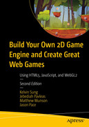
The translation operator T(tx,ty), as illustrated in Figure 3-2, translates or moves a given vertex position from (x, y) to (x+tx, y+ty). Notice that T(0,0) does not change the value of a given vertex position and is a convenient initial value for accumulating translation operations.
Translating a square by T(tx, ty)
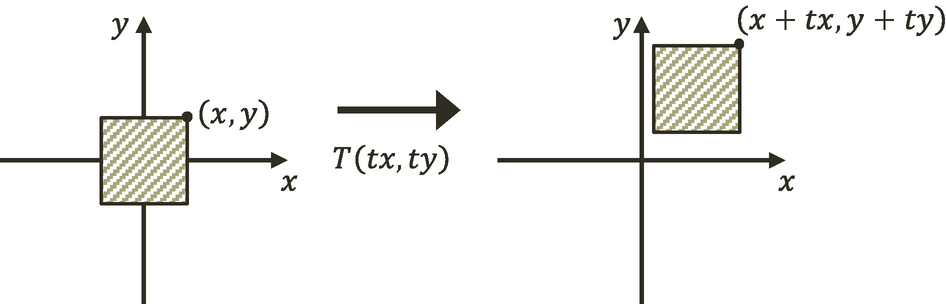
The scaling operator S(sx, sy), as illustrated by Figure 3-3, scales or resizes a given vertex position from (x, y) to (x×sx, y×sy). Notice that S(1, 1) does not change the value of a given vertex position and is a convenient initial value for accumulating scaling operations.
Scaling a square by S(sx, sy)
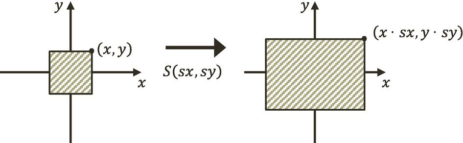
The rotation operator R(θ) , as illustrated in Figure 3-4, rotates a given vertex position with respect to the origin.
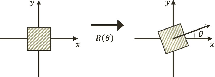
Rotating a square by R(θ)
The identity operator I does not affect a given vertex position. This operator is mostly used for initialization.


The z component is the third dimension, or the depth information, of a vertex position. In most cases, you should leave the z component to be 0.

Concatenation of Matrix Operators


The M operator is a convenient and efficient way to record and reapply the results of multiple operators.

The glMatrix Library
- 1.
Create a new folder under the src folder, and name the new folder lib.
- 2.
Go to http://glMatrix.net, as shown in Figure 3-5, and download, unzip, and store the resulting glMatrix.js source file into the new lib folder.
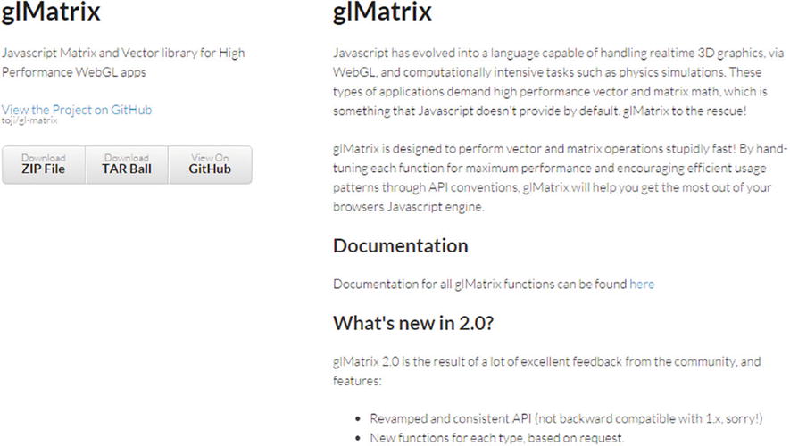
Downloading the glMatrix library
- 3.
As a library that must be accessible by both the game engine and the client game developer, you will load the source file in the main index.html by adding the following before the loading of my_game.js:
The Matrix Transform Project

Running the Matrix Transform project
To introduce transformation matrices as operators for drawing a Renderable
To understand how to work with the transform operators to manipulate a Renderable
Modify the Vertex Shader to Support Transforms
As discussed, matrix transform operators operate on vertices of geometries. The vertex shader is where all vertices are passed in from the WebGL context and is the most convenient location to apply the transform operations.
- 1.
Edit simple_vs.glsl to declare a uniform 4×4 matrix:
Recall from the discussion in Chapter 2 that glsl files contain OpenGL Shading Language (GLSL) instructions that will be loaded to and executed by the GPU. You can find out more about GLSL by referring to the WebGL and OpenGL references provided at the end of Chapter 1.
Recall that the uniform keyword in a GLSL shader declares a variable with values that do not change for all the vertices within that shader. In this case, the uModelXformMatrix variable is the transform operator for all the vertices.
GLSL uniform variable names always begin with lowercase “u”, as in uModelXformMatrix.
- 2.
In the main() function, apply the uModelXformMatrix to the currently referenced vertex position:
Notice that the operation follows directly from the discussion on matrix transformation operators. The reason for converting aVertexPosition to a vec4 is to support the matrix-vector multiplication.
With this simple modification, the vertex positions of the unit square will be operated on by the uModelXformMatrix operator, and thus the square can be drawn to different locations. The task now is to set up SimpleShader to load the appropriate transformation operator into uModelXformMatrix .
Modify SimpleShader to Load the Transform Operator
- 1.
Edit simple_shader.js and add an instance variable to hold the reference to the uModelXformMatrix matrix in the vertex shader:
- 2.
At the end of the SimpleShader constructor under step E, after setting the reference to uPixelColor, add the following code to initialize this reference:
- 3.
Modify the activate() function to receive a second parameter, and load the value to uModelXformMatrix via mModelMatrixRef:
The gl.uniformMatrix4fv() function copies the values from trsMatrix to the vertex shader location identified by this.mModelMatrixRef or the uModelXfromMatrix operator in the vertex shader. The name of the variable, trsMatrix, signifies that it should be a matrix operator containing the concatenated result of translation (T), rotation (R), and scaling (S) or TRS.
Modify Renderable Class to Set the Transform Operator
In this way, when the vertices of the unit square are processed by the vertex shader, the uModelXformMatrix will contain the proper operator for transforming the vertices and thus drawing the square at the desired location, size, and rotation.
Testing the Transforms
- 1.
Edit my_game.js; after step C, instead of activating and drawing the two squares, replace steps C1 and C2 to create a new identity transform operator, trsMatrix:
- 2.
Compute the concatenation of matrices to a single transform operator that implements translation (T), rotation (R), and scaling (S) or TRS:
- 3.
Finally, step F defines the trsMatrix operator that to draw a 0.4×0.4 square that is rotated by 45 degrees and located slightly toward the lower right from the center of the canvas, and step G draws the red square:
Observations
Run the project, and you should see the corresponding white and red rectangles drawn on the canvas. You can gain some intuition of the operators by changing the values; for example, move and scale the squares to different locations with different sizes. You can try changing the order of concatenation by moving the corresponding line of code; for example, move mat4.scale() to before mat4.translate(). You will notice that, in general, the transformed results do not correspond to your intuition. In this book, you will always apply the transformation operators in the fixed TRS order. This ordering of transformation operators corresponds to typical human intuition. The TRS operation order is followed by most, if not all, graphical APIs and applications that support transformation operations.
Now that you understand how to work with the matrix transformation operators, it is time to abstract them and hide their details.
Encapsulating the Transform Operator
In the previous project, the transformation operators were computed directly based on the matrices. While the results were important, the computation involves distracting details and repetitive code. This project guides you to follow good coding practices to encapsulate the transformation operators by hiding the detailed computations with a class. In this way, you can maintain the modularity and accessibility of the game engine by supporting further expansion while maintaining programmability.
The Transform Objects Project

Running the Transform Objects project
To create the Transform class to encapsulate the matrix transformation functionality
To integrate the Transform class into the game engine
To demonstrate how to work with Transform objects
The Transform Class
- 1.
Define the Transform class in the game engine by creating a new source code file in the src/engine folder , and name the file transform.js.
- 2.
Define the constructor to initialize instance variables that correspond to the operators: mPosition for translation, mScale for scaling, and mRotationInRad for rotation.
- 3.
Add getters and setters for the values of each operator:
- 4.
Define the getTRSMatrix() function to compute and return the concatenated transform operator, TRS:
- 5.
Finally, remember to export the newly defined Transform class :
The Transformable Renderable Class
- 1.
Edit renderable.js and add a new instance variable to reference a Transform object in the constructor:
- 2.
Define an accessor for the transform operator:
- 3.
Modify the draw() function to pass the trsMatrix operator of the mXform object to activate the shader before drawing the unit square:
With this simple modification, Renderable objects will be drawn with characteristics defined by the values of its own transformation operators.
Modify the Engine Access File to Export Transform
- 1.
Edit index.js; import from the newly define transform.js file:
- 2.
Export Transform for client’s access:
Modify Drawing to Support Transform Object
Run the project to observe identical output as from the previous project. You can now create and draw a Renderable at any location in the canvas, and the transform operator has now been properly encapsulated.
The Camera Transform and Viewports
When designing and building a video game, the game designers and programmers must be able to focus on the intrinsic logic and presentation. To facilitate these aspects, it is important that the designers and programmers can formulate solutions in a convenient dimension and space.
For example, continuing with the soccer game idea, consider the task of creating a soccer field. How big is the field? What is the unit of measurement? In general, when building a game world, it is often easier to design a solution by referring to the real world. In the real world, soccer fields are around 100 meters long. However, in the game or graphics world, units are arbitrary. So, a simple solution may be to create a field that is 100 units in meters and a coordinate space where the origin is located at the center of the soccer field. In this way, opposing sides of the fields can simply be determined by the sign of the x value, and drawing a player at location (0, 1) would mean drawing the player 1 meter to the right from the center of the soccer field.
A contrasting example would be when building a chess-like board game. It may be more convenient to design the solution based on a unitless n×n grid with the origin located at the lower-left corner of the board. In this scenario, drawing a piece at location (0, 1) would mean drawing the piece at the location one cell or unit toward the right from the lower-left corner of the board. As will be discussed, the ability to define specific coordinate systems is often accomplished by computing and working with a matrix representing the view from a camera.
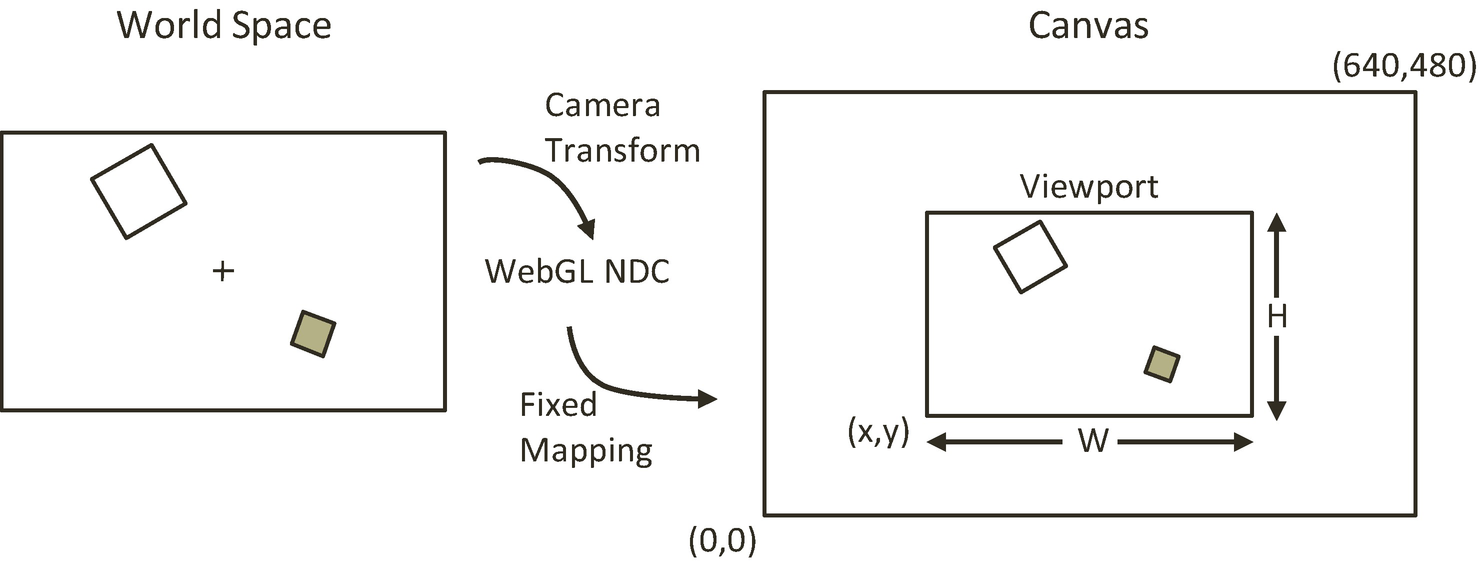
In all cases, to support a proper presentation of the game, it is important to allow the programmer to control the drawing of the contents to any location on the canvas. For example, you may want to draw the soccer field and players to one subregion and draw a mini-map into another subregion. These axis-aligned rectangular drawing areas or subregions of the canvas are referred to as viewports.
In this section, you will learn about coordinate systems and how to use the matrix transformation as a tool to define a drawing area that conforms to the fixed ±1 drawing range of the WebGL.
Coordinate Systems and Transformations
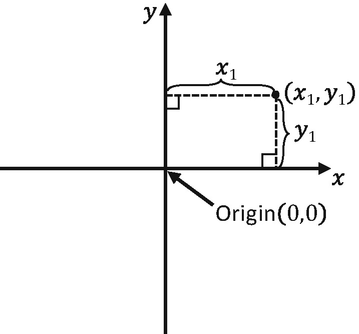
Working with a 2D Cartesian coordinate system
Modeling and Normalized Device Coordinate Systems
So far in this book, you have experience with two distinct coordinate systems. The first is the coordinate system that defines the vertices for the 1×1 square in the vertex buffer. This is referred to as the Modeling Coordinate System, which defines the Model Space. The Model Space is unique for each geometric object, as in the case of the unit square. The Model Space is defined to describe the geometry of a single model. The second coordinate system that you have worked with is the one that WebGL draws to, where the x-/y-axis ranges are bounded to ±1.0. This is known as the Normalized Device Coordinate (NDC) System. As you have experienced, WebGL always draws to the NDC space and that the contents in the ±1.0 range cover all the pixels in the canvas.
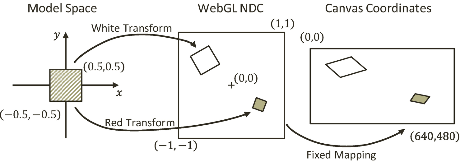
Transforming the square from Model to NDC space
The World Coordinate System
Although it is possible to draw to any location with the Modeling transform, the disproportional scaling that draws squares as rectangles is still a problem. In addition, the fixed -1.0 and 1.0 NDC space is not a convenient coordinate space for designing games. The World Coordinate (WC) System describes a convenient World Space that resolves these issues. For convenience and readability, in the rest of this book, WC will also be used to refer to the World Space that is defined by a specific World Coordinate System.
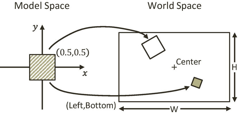
Working with a World Coordinate (WC) System

In this case, (center.x, center.y) and WxH are the center and the dimension of the WC system.
The Viewport
Working with the WebGL viewport
The Camera Transform and Viewport Project

Running the Camera Transform and Viewport project
To understand the different coordinate systems
To experience working with a WebGL viewport to define and draw to different subregions within the canvas
To understand the Camera transform
To begin drawing to the user-defined World Coordinate System
You are now ready to modify the game engine to support the Camera transform to define your own WC and the corresponding viewport for drawing. The first step is to modify the shaders to support a new transform operator.
Modify the Vertex Shader to Support the Camera Transform
- 1.
Edit simple_vs.glsl to add a new uniform matrix operator to represent the Camera transform:
- 2.
Make sure to apply the operator on the vertex positions in the vertex shader program:
Recall that the order of matrix operations is important. In this case, the uModelXformMatrix first transforms the vertex positions from Model Space to WC, and then the uCameraXformMatrix transforms from WC to NDC. The order of uModelxformMatrix and uCameraXformMatrix cannot be switched.
Modify SimpleShader to Support the Camera Transform
- 1.
Edit simple_shader.js and, in the constructor, add an instance variable for storing the reference to the Camera transform operator in simple_vs.glsl:
- 2.
At the end of the SimpleShader constructor, retrieve the reference to the Camera transform operator, uCameraXformMatrix, after retrieving those for the uModelXformMatrix and uPixelColor:
- 3.
Modify the activate function to receive a Camera transform matrix and pass it to the shader:
As you have seen previously, the gl.uniformMatrix4fv() function copies the content of cameraMatrix to the uCameraXformMatrix operator .
Modify Renderable to Support the Camera Transform
It is now possible to set up a WC for drawing and define a subarea in the canvas to draw to.
Design the Scene

Designing a WC to support drawing
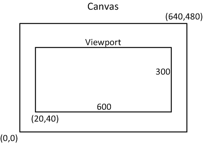
Drawing the WC to the viewport
Note that the details of the WC, centered at (20, 60) with dimension 20x10, and the viewport, lower-left corner at (20, 40) and dimension of 600x300, are chosen rather randomly. These are simply reasonable values that can demonstrate the correctness of the implementation.
Implement the Design
- 1.
Edit my_game.js. In the constructor, perform step A to initialize the game engine and step B to create six Renderable objects (two to be drawn at the center, with four at each corner of the WC) with corresponding colors.
- 2.
Steps C and D clear the entire canvas, set up the viewport, and clear the viewport to a different color:
- 3.
Step E defines the WC with the Camera transform by concatenating the proper scaling and translation operators:
- a.
Center: (20,60)
- b.
Top-left corner: (10, 65)
- c.
Top-right corner: (30, 65)
- d.
Bottom-right corner: (30, 55)
- e.
Bottom-left corner: (10, 55)
- 4.
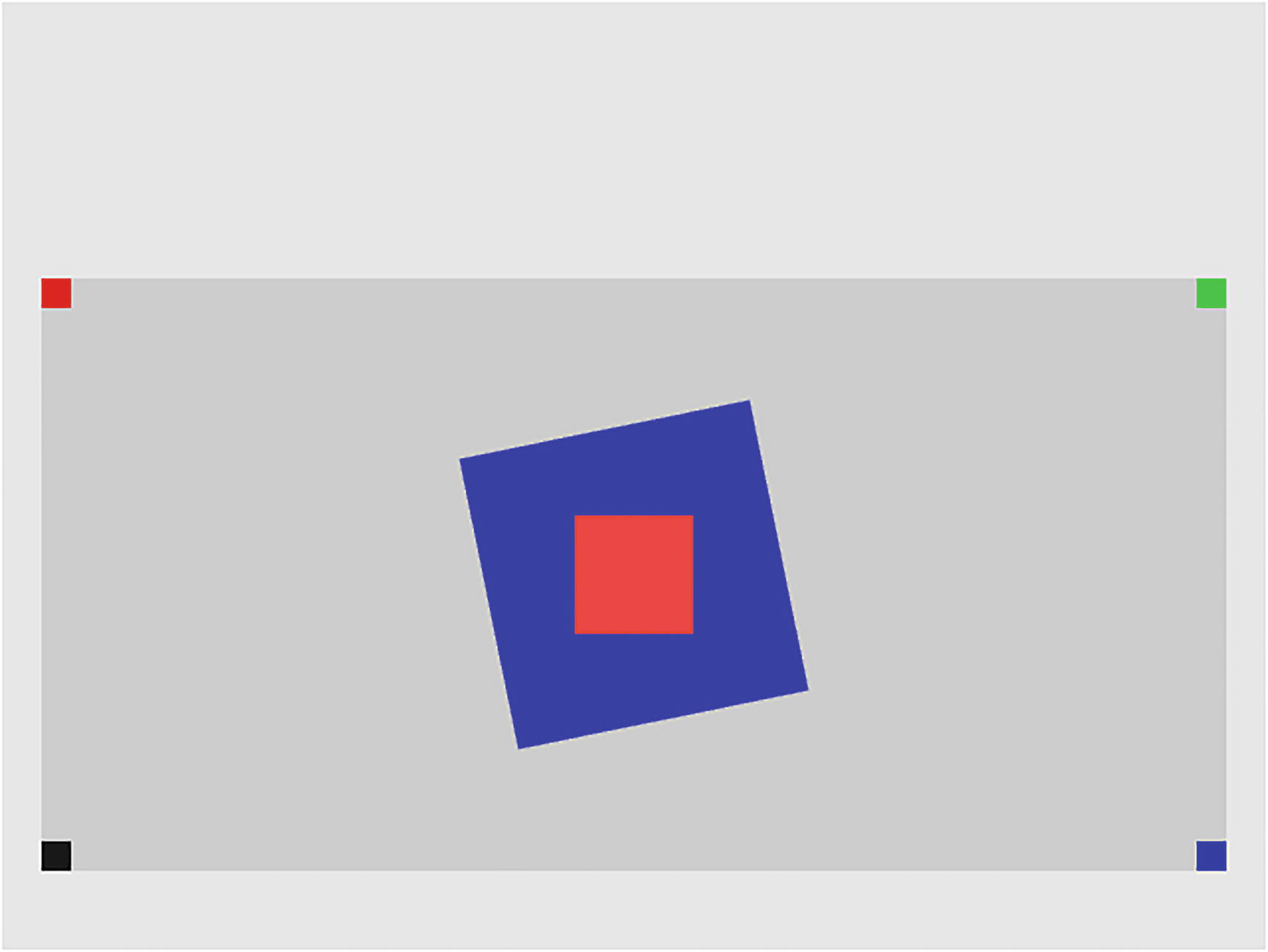
Set up the slightly rotated 5x5 blue square at the center of WC, and draw with the Camera transform operator, cameraMatrix:
- 5.
Now draw the other five squares, first the 2x2 in the center and one each at a corner of the WC:
Run this project and observe the distinct colors at the four corners: the top left (mTLSq) in red, the top right (mTRSq) in green, the bottom right (mBRSq) in blue, and the bottom left (mBLSq) in dark gray. Change the locations of the corner squares to verify that the center positions of these squares are located in the bounds of the WC, and thus, only one quarter of the squares are actually visible. For example, set mBlSq to (12, 57) to observe the dark-gray square is actually four times the size. This observation verifies that the areas of the squares outside of the viewport/scissor area are clipped by WebGL.
Although lacking proper abstraction, it is now possible to define any convenient WC system and any rectangular subregions of the canvas for drawing. With the Modeling and Camera transformations, a game programmer can now design a game solution based on the semantic needs of the game and ignore the irrelevant WebGL NDC drawing range. However, the code in the MyGame class is complicated and can be distracting. As you have seen so far, the important next step is to define an abstraction to hide the details of Camera transform matrix computation.
The Camera
The Camera transform allows the definition of a WC. In the physical world, this is analogous to taking a photograph with the camera. The center of the viewfinder of your camera is the center of the WC, and the width and height of the world visible through the viewfinder are the dimensions of WC. With this analogy, the act of taking the photograph is equivalent to computing the drawing of each object in the WC. Lastly, the viewport describes the location to display the computed image.
The Camera Objects Project
Running the Camera Objects project
To define the Camera class to encapsulate the definition of WC and the viewport functionality
To integrate the Camera class into the game engine
To demonstrate how to work with a Camera object
The Camera Class
- 1.
Define the Camera class in the game engine by creating a new source file in the src/engine folder, and name the file camera.js.
- 2.
Add the constructor for Camera:
The Camera defines the WC center and width, the viewport, the Camera transform operator, and a background color. Take note of the following:
- a.
The mWCCenter is a vec2 (vec2 is defined in the glMatrix library). It is a float array of two elements. The first element, index position 0, of vec2 is the x, and the second element, index position 1, is the y position.
- b.
The four elements of the viewportArray are the x and y positions of the lower-left corner and the width and height of the viewport, in that order. This compact representation of the viewport keeps the number of instance variables to a minimum and helps keep the Camera class manageable.
- c.
The mWCWidth is the width of the WC. To guarantee a matching aspect ratio between WC and the viewport, the height of the WC is always computed from the aspect ratio of the viewport and mWCWidth.
- d.
mBgColor is an array of four floats representing the red, green, blue, and alpha components of a color.
- 3.
Outside of the Camera class definition, define enumerated indices for accessing the viewportArray:
Enumerated elements have names that begin with lowercase “e”, as in eViewport and eOrgX.
- 4.
Define the function to compute the WC height based on the aspect ratio of the viewport:
- 5.
Add getters and setters for the instance variables:
- 6.
Create a function to set the viewport and compute the Camera transform operator for this Camera:
- 7.
The code to configure the viewport under step A is as follows:
- 8.
The code to set up the Camera transform operator under step B is as follows:
- 9.
Define a function to access the computed camera matrix:
- 10.
Finally, remember to export the newly defined Camera class:
Modify Renderable to Support the Camera Class
Modify the Engine Access File to Export Camera
- 1.
Edit index.js; import from the newly define camera.js file:
- 2.
Export Camera for client’s access:
Test the Camera
- 1.
Edit my_game.js; after the initialization of the game engine in step A, create an instance of the Camera object with settings that define the WC and viewport from the previous project in step B:
- 2.
Continue with the creation of the six Renderable objects and the clearing of the canvas in steps C and D:
- 3.
Now, call the setViewAndCameraMatrix() function of the Camera object in to configure the WebGL viewport and compute the camera matrix in step E, and draw all the Renderables using the Camera object in steps F and G.
The mCamera object is passed to the draw() function of the Renderable objects such that the Camera transform matrix operator can be retrieved and used to activate the shader.
Summary
In this chapter, you learned how to create a system that can support the drawing of many objects. The system is composed of three parts: the objects, the details of each object, and the display of the objects on the browser’s canvas. The objects are encapsulated by the Renderable, which uses a Transform to capture its details—the position, size, and rotation. The particulars of displaying the objects are defined by the Camera, where objects at specific locations can be displayed at desirable subregions on the canvas.
You also learned that objects are all drawn relative to a World Space or WC, a convenient coordinate system. A WC is defined for scene compositions based on coordinate transformations. Lastly, the Camera transform is used to select which portion of the WC to actually display on the canvas within a browser. This can be achieved by defining an area that is viewable by the Camera and using the viewport functionality provided by WebGL.
As you built the drawing system, the game engine source code structure has been consistently refactored into abstracted and encapsulated components. In this way, the source code structure continues to support further expansion including additional functionality which will be discussed in the next chapter.