Implement autonomous behaviors such as target-locked chasing and gradual turning
Collide textured objects accurately
Understand the efficiency concerns of pixel-accurate collision
Program with pixel-accurate collision effectively and efficiently
Introduction
By this point, your game engine is capable of implementing games in convenient coordinate systems as well as presenting and animating objects that are visually appealing. However, there is a lack of abstraction support for the behaviors of objects. You can see the direct results of this shortcoming in the init() and update() functions of the MyGame objects in all the previous projects: the init() function is often crowded with mundane per-game object settings, while the update() function is often crowded with conditional statements for controlling objects, such as checking for key presses for moving the hero.
A well-designed system should hide the initialization and controls of individual objects with proper object-oriented abstractions or classes. An abstract GameObject class should be introduced to encapsulate and hide the specifics of its initialization and behaviors. There are two main advantages to this approach. First, the init() and update() functions of a game level can focus on managing individual game object and the interactions of these objects without being clustered with details specific to different types of objects. Second, as you have experienced with the Renderable and SimpleShader class hierarchies, proper object-oriented abstraction creates a standardized interface and facilitates code sharing and reuse.
As you transition from working with the mere drawing of objects (in other words, Renderable) to programming with the behavior of objects (in other words, GameObject), you will immediately notice that for the game to be entertaining or fun, the objects need to interact. Interesting behaviors of objects, such as facing or evading enemies, often require the knowledge of the relative positions of other objects in the game. In general, resolving relative positions of all objects in a 2D world is nontrivial. Fortunately, typical video games require the knowledge of only those objects that are in close proximity to each other or are about to collide or have collided.
An efficient but somewhat crude approximation to detect collision is to compute the bounds of an object and approximate object collisions based on colliding bounding boxes. In the simplest cases, bounding boxes are rectangular boxes with edges that are aligned with the x/y axes. These are referred to as axis-aligned bounding boxes or AABBs. Because of the axis alignments, it is computationally efficient to detect when two AABBs overlap or when collision is about to occur.
Many 2D game engines can also detect the actual collision between two textured objects by comparing the location of pixels from both objects and detecting the situation when at least one of the nontransparent pixels overlaps. This computationally intensive process is known as per-pixel-accurate collision detection, pixel-accurate collision, or per-pixel collision.
This chapter begins by introducing the GameObject class to provide a platform for abstracting game object behaviors. The GameObject class is then generalized to introduce common behavior attributes including speed, movement direction, and target-locked chasing. The rest of the chapter focuses on deriving an efficient per-pixel accurate collision implementation that supports both textured and animated sprite objects.
Game Objects
As mentioned, an abstraction that encapsulates the intrinsic behavior of typical game objects should be introduced to minimize the clustering of code in the init() and update() functions of a game level and to facilitate reuse. This section introduces the simple GameObject class to illustrate how the cleaner and uncluttered init() and update() functions clearly reflect the in-game logic and to demonstrate how the basic platform for abstracting object behaviors facilitates design and code reuse.
The Game Objects Project
Running the Game Objects project
WASD keys : Move the hero up, left, down, and right
To begin defining the GameObject class to encapsulate object behaviors in games
To demonstrate the creation of subclasses to the GameObject class to maintain the simplicity of the MyGame level update() function
To introduce the GameObjectSet class demonstrating support for a set of homogenous objects with an identical interface
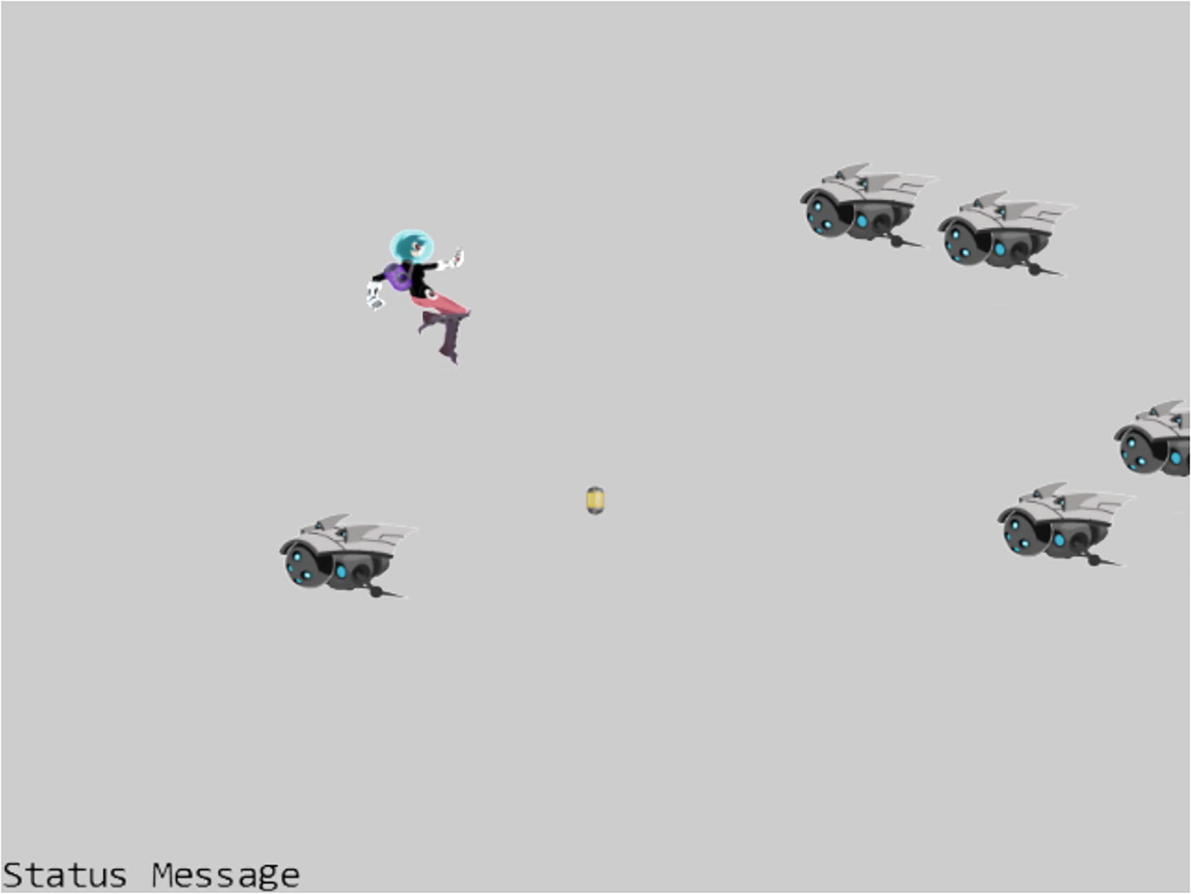
The new sprite elements of the minion_sprite.png image
Define the GameObject Class
- 1.
Add a new folder src/engine/game_objects for storing GameObject-related files.
- 2.
Create a new file in this folder, name it game_object.js, and add the following code:
With the assessors to the Renderable and Transform objects defined, all GameObject instances can be drawn and have defined locations and sizes. Note that the update() function is designed for subclasses to override with per object–specific behaviors, and thus, it is left empty.
Manage Game Objects in Sets
- 1.
Create a new file in the src/engine/game_objects folder and name it game_object_set.js. Define the GameObjectSet class and the constructor to initialize an array for holding GameObject instances.
- 2.
Define functions for managing the set membership:
- 3.
Define functions to update and draw each of the GameObject instances in the set:
Export the Classes to the Client
This process of import/export classes via the engine access file, index.js, must be repeated for every newly defined functionality. Henceforth, only a reminder will be provided and the straightforward code change will not be shown again.
Test the GameObject and GameObjectSet
The goals of this project are to ensure proper functioning of the new GameObject class, to demonstrate customization of behaviors by individual object types, and to observe a cleaner MyGame implementation clearly reflecting the in-game logic. To accomplish these goals, three object types are defined: DyePack, Hero, and Minion. Before you begin to examine the detailed implementation of these objects, follow good source code organization practice and create a new folder src/my_game/objects for storing the new object types.
The DyePack GameObject
The DyePack class derives from the GameObject class to demonstrate the most basic example of a GameObject: an object that has no behavior and is simply drawn to the screen.
Notice that even without specific behaviors, the DyePack is implementing code that used to be found in the init() function of the MyGame level. In this way, the DyePack object hides specific geometric information and simplifies the MyGame level .
The need to import from the engine access file, index.js, is true for almost all client source code file and will not be repeated.
The Hero GameObject
- 1.
Create a new file in the src/my_game/objects folder and name it hero.js. Define Hero as a subclass of GameObject, and implement the constructor to initialize the sprite UV values, size, and position. Make sure to export and share this class.
- 2.
Add a function to support the update of this object by user keyboard control. The Hero object moves at a kDelta rate based on WASD input from the keyboard.
The Minion GameObject
- 1.
Create a new file in the src/my_game/objects folder and name it minion.js. Define Minion as a subclass of GameObject, and implement the constructor to initialize the sprite UV values, sprite animation parameters, size, and position as follows:
- 2.
Add a function to update the sprite animation, support the simple right-to-left movements, and provide the wrapping functionality:
The MyGame Scene
- 1.
In addition to the engine access file, index.js, in order to gain access to the newly defined objects, the corresponding source code must be imported:
As is the case for other import/export statements, unless there are other specific reasons, this reminder will not be shown again.
- 2.
The constructor and the load(), unload(), and draw() functions are similar as in previous projects, so the details are not shown here.
- 3.
Edit the init() function and add the following code:
- 4.
Edit the update() function to update the game state :
With the well-defined behaviors for each object type abstracted, the clean update() function clearly shows that the game consists of three noninteracting objects.
Observation
You can now run the project and notice that the slightly more complex movements of six minions are accomplished with much cleaner init() and update() functions. The init() function consists of only logic and controls for placing created objects in the game world and does not include any specific settings for different object types. With the Minion object defining its motion behaviors in its own update() function, the logic in the MyGame update() function can focus on the details of the level. Note that the structure of this function clearly shows that the three objects are updated independently and do not interact with each other .
Throughout this book, in almost all cases, MyGame classes are designed to showcase the engine functionality. As a result, the source code organization in most MyGame classes may not represent the best practices for implementing games.
Creating a Chase Behavior
A closer examination of the previous project reveals that though there are quite a few minions moving on the screen, their motions are simple and boring. Even though there are variations in speed and direction, the motions are without purpose or awareness of other game objects in the scene. To support more sophisticated or interesting movements, a GameObject needs to be aware of the locations of other objects and determine motion based on that information.
Chasing behavior is one such example. The goal of a chasing object is usually to catch the game object that it is targeting. This requires programmatic manipulation of the front direction and speed of the chaser such that it can hone in on its target. However, it is generally important to avoid implementing a chaser that has perfect aim and always hits its target—because if the player is unable to avoid being hit, the game becomes impossibly difficult. Nonetheless, this does not mean you should not implement a perfect chaser if your game design requires it. You will implement a chaser in the next project.
Vectors and the associated operations are the foundation for implementing object movements and behaviors. Before programming with vectors, a quick review is provided. As in the case of matrices and transform operators, the following discussion is not meant to be a comprehensive coverage of vectors. Instead, the focus is on the application of a small collection of concepts that are relevant to the implementation of the game engine. This is not a study of the theories behind the mathematics. If you are interested in the specifics of vectors and how they relate to games, please refer to the discussion in Chapter 1 where you can learn more about these topics in depth by delving into relevant books on linear algebra and games.
Vectors Review
Vectors are used across many fields of study, including mathematics, physics, computer science, and engineering. They are particularly important in games; nearly every game uses vectors in one way or another. Because they are used so extensively, this section is devoted to understanding and utilizing vectors in games.
For an introductory and comprehensive coverage of vectors, you can refer to www.storyofmathematics.com/vectors. For more detailed coverage of vector applications in games, you can refer to Basic Math for Game Development with Unity 3D: A Beginner’s Guide to Mathematical Foundations, Apress, 2019.
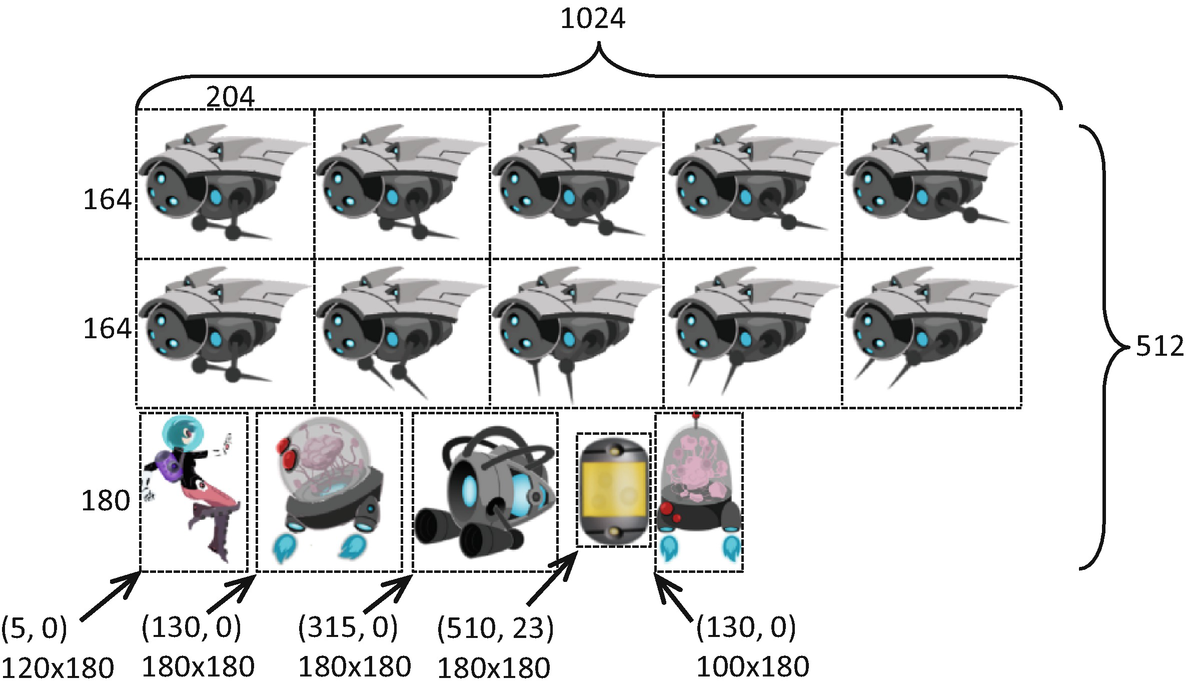
One of the most common uses for vectors is to represent an object’s displacement and direction or velocity. This can be done easily because a vector is defined by its size and direction. Using only this small amount of information, you can represent attributes such as the velocity or acceleration of an object. If you have the position of an object, its direction, and its velocity, then you have sufficient information to move it around the game world without user input.
 as Pb − Pa. You can see this represented in the following equations and
Figure 6-3:
as Pb − Pa. You can see this represented in the following equations and
Figure 6-3:Pa = (xa, ya)
Pb = (xb, yb)

A vector defined by two points
Now that you have a vector  , you can easily determine its length (or size) and direction. A vector’s length is equal to the distance between the two points that created it. In this example, the length of
  is equal to the distance between Pa and Pb, while the direction of
  goes from Pa toward Pb.
The size of a vector is often referred to as its length or magnitude.
In the gl-matrix library, the vec2 object implements the functionality of a 2D vector. Conveniently, you can also use the vec2 object to represent 2D points or positions in space. In the preceding example, Pa, Pb, and  can all be implemented as instances of the vec2 object. However,
  is the only mathematically defined vector. Pa and Pb represent positions or points used to create a vector.
 and for a normalized vector is
  :
: : Normalizes vector
  and stores the results to the vec2 object
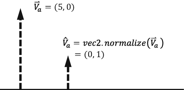
A vector being normalized
 represents the direction from the origin to the position (xv, yv) and you want to rotate it by θ, then, as illustrated in Figure 6-5
, you can use the following equations to derive xr and yr:
represents the direction from the origin to the position (xv, yv) and you want to rotate it by θ, then, as illustrated in Figure 6-5
, you can use the following equations to derive xr and yr:xr = xv cos θ − yv sin θ
yr = xv sin θ + yv cos θ

A vector from the origin to the position (xv, yv) being rotated by the angle theta
JavaScript trigonometric functions, including the Math.sin() and Math.cos() functions, assume input to be in radians and not degrees. Recall that 1 degree is equal to  radians.
 and
and  that are located at different positions but have the same direction and magnitude and thus are equal to each other. In contrast, the vector
  is not the same because its direction and magnitude are different from the others.
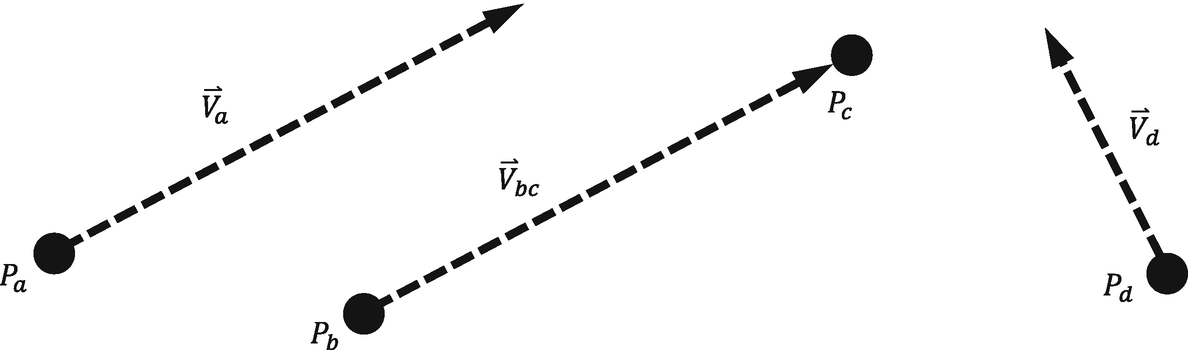
Three vectors represented in 2D space with two vectors equal to each other
The Dot Product


 .
.
 and
and  are normalized, then
 and
and  vectors with an angle θ in between them. It is also important to recognize that if
  , then the two vectors are perpendicular.
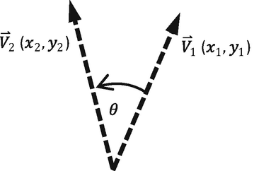
The angle between two vectors, which can be found through the dot product
If you need to review or refresh the concept of a dot product, please refer to www.mathsisfun.com/algebra/vectors-dot-product.html.
The Cross Product


 is a vector perpendicular to both
  and
and  .
.
 , you know that
  is in the clockwise direction from
  similarly, when
  , you know that
  is in the counterclockwise direction. Figure 6-8 should help clarify this concept.
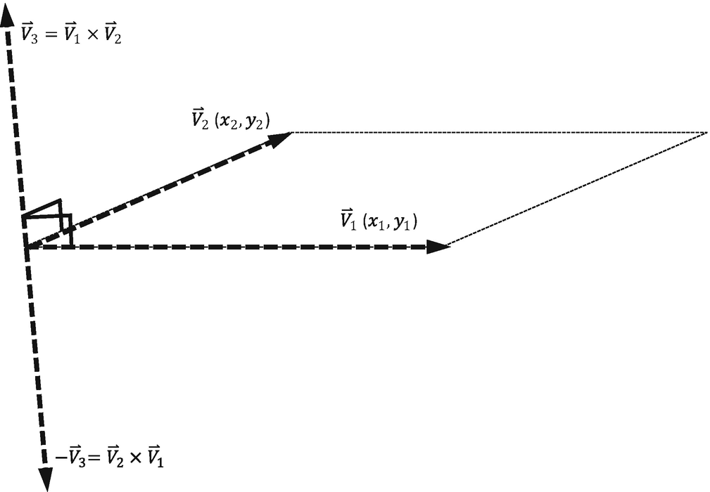
The cross product of two vectors
If you need to review or refresh the concept of a cross product, please refer to www.mathsisfun.com/algebra/vectors-cross-product.html.
The Front and Chase Project
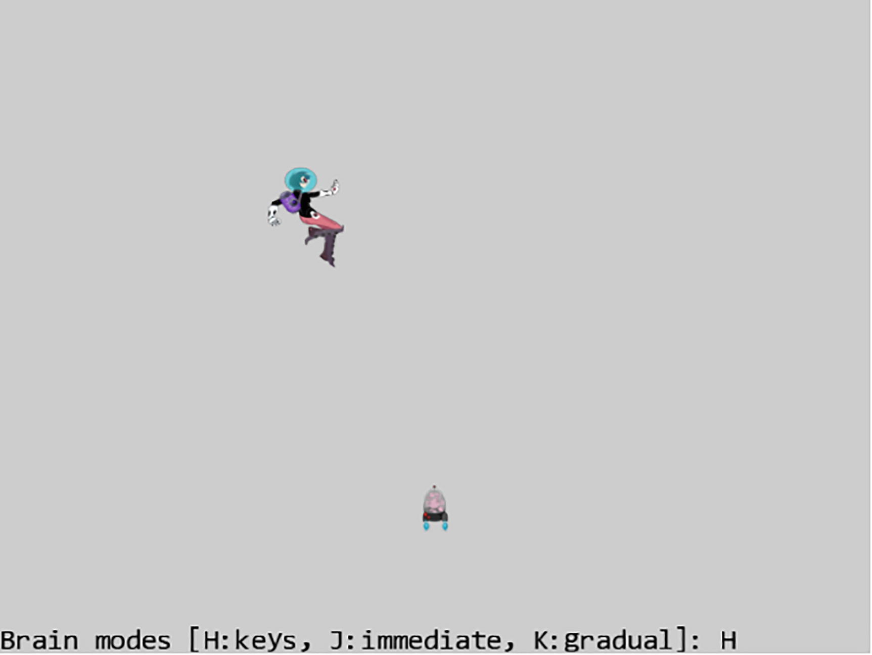
Running the Front and Chase project
WASD keys: Moves the Hero object
Left-/right-arrow keys: Change the front direction of the Brain object when it is under user control
Up-/down-arrow keys: Increase/decrease the speed of the Brain object
H key: Switches the Brain object to be under user arrow keys control
J key: Switches the Brain object to always point at and move toward the current Hero object position
K key: Switches the Brain object to turn and move gradually toward the current Hero object position
To experience working with speed and direction
To practice traveling along a predefined direction
To implement algorithms with vector dot and cross products
To examine and implement chasing behavior
You can find the same external resource files as in the previous project in the assets folder.
Add Vector Rotation to the gl-matrix Library
This modification to the gl-matrix library must be present in all projects from this point forward.
Modify GameObject to Support Interesting Behaviors
- 1.
Edit the game_object.js file and modify the GameObject constructor to define visibility, front direction, and speed:
- 2.
Add assessor and setter functions for the instance variables:
- 3.
Implement a function to rotate the front direction toward a position, p:
- a.
Step A computes the distance between the current object and the destination position p. If this value is small, it means current object and the target position are close. The function returns without further processing.
- b.
Step B, as illustrated in Figure 6-10, computes the dot product to determine the angle θ between the current front direction of the object (fdir) and the direction toward the destination position p (dir). If these two vectors are pointing in the same direction (cosθ is almost 1 or θ almost zero), the function returns.
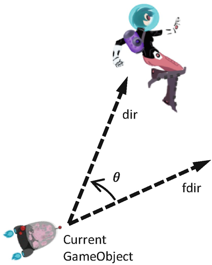
A GameObject (Brain) chasing a target (Hero)
- c.
Step C checks for the range of cosTheta. This is a step that must be performed because of the inaccuracy of floating-point operations in JavaScript.
- d.
Step D uses the results of the cross product to determine whether the current GameObject should be turning clockwise or counterclockwise to face toward the destination position p.
- e.
Step E rotates mCurrentFrontDir and sets the rotation in the Transform of the Renderable object. It is important to recognize the two separate object rotation controls. The Transform controls the rotation of what is being drawn, and mCurrentFrontDir controls the direction of travel. In this case, the two are synchronized and thus must be updated with the new value simultaneously.
- 4.
Add a function to update the object’s position with its direction and speed. Notice that if the mCurrentFrontDir is modified by the rotateObjPointTo() function, then this update() function will move the object toward the target position p, and the object will behave as though it is chasing the target.
- 5.
Add a function to draw the object based on the visibility setting:
Test the Chasing Functionality
The strategy and goals of this test case are to create a steerable Brain object to demonstrate traveling along a predefined front direction and to direct the Brain to chase after the Hero to demonstrate the chasing functionality.
Define the Brain GameObject
- 1.
Create a new file in the src/my_game/objects folder and name it brain.js. Define Brain as a subclass of GameObject, and implement the constructor to initialize the appearance and behavior parameters.
- 2.
Override the update() function to support the user steering and controlling the speed. Notice that the default update() function in the GameObject must be called to support the basic traveling of the object along the front direction according to its speed.
The MyGame Scene
In the update() function, the switch statement uses mMode to determine how to update the Brain object. In the cases of J and K modes, the Brain object turns toward the Hero object position with the rotateObjPointTo() function call. While in the H mode, the Brain object’s update() function is called for the user to steer the object with the arrow keys. The final three if statements simply set the mMode variable according to user input.
Note that in the cases of J and K modes, in order to bypass the user control logic after the rotateObjPointTo(), the update() function being called is the one defined by the GameObject and not by the Brain.
The JavaScript syntax, ClassName.prototype.FunctionName.call(anObj), calls FunctionName defined by ClassName, where anObj is a subclass of ClassName.
Observation
You can now try running the project. Initially, the Brain object is under the user’s control. You can use the left- and right-arrow keys to change the front direction of the Brain object and experience steering the object. Pressing the J key causes the Brain object to immediately point and move toward the Hero object. This is a result of the default turn rate value of 1.0. The K key causes a more natural behavior, where the Brain object continues to move forward and gradually turns to move toward the Hero object. Feel free to change the values of the rate variable or modify the control value of the Brain object. For example, change the kDeltaRad or kDeltaSpeed to experiment with different settings for the behavior.
Collisions Between GameObjects
In the previous project, the Brain object would never stop traveling. Notice that under the J and K modes, the Brain object would orbit or rapidly flip directions when it reaches the target position. The Brain object is missing the critical ability to detect that it has collided with the Hero object, and as a result, it never stops moving. This section describes axis-aligned bounding boxes (AABBs), one of the most straightforward tools for approximating object collisions, and demonstrates the implementation of collision detection based on AABB.
Axis-Aligned Bounding Box (AABB)
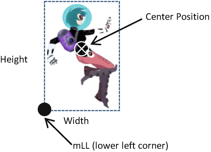
The lower-left corner and size of the bounds for an object
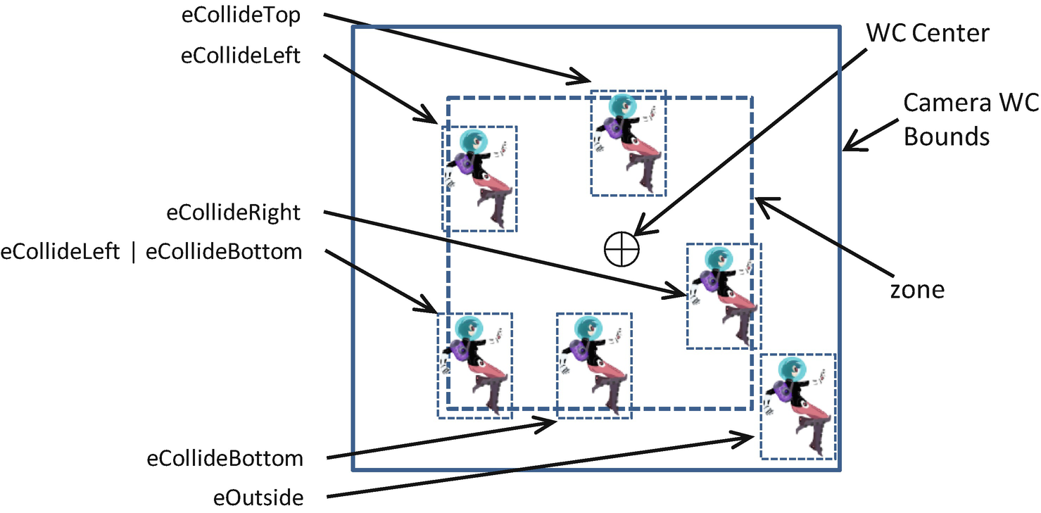
It is interesting to note that in addition to representing the bounds of an object, bounding boxes can be used to represent the bounds of any given rectangular area. For example, recall that the WC visible through the Camera is a rectangular area with the camera’s position located at the center and the WC width/height defined by the game developer. An AABB can be defined to represent the visible WC rectangular area, or the WC window, and used for detecting collision between the WC window and GameObject instances in the game world.
In this book, AABB and “bounding box” are used interchangeably.
The Bounding Box and Collisions Project
Running the Bounding Box and Collisions project
WASD keys: Moves the Hero object
Left-/right-arrow keys: Change the front direction of the Brain object when it is under user control
Up-/down-arrow keys: Increase/decrease the speed of the Brain object
H key: Switches the Brain object to be under user arrow keys control
J key: Switches the Brain object to always point at and move toward the current Hero object position
K key: Switches the Brain object to turn and move gradually toward the current Hero object position
To understand the implementation of the bounding box class
To experience working with the bounding box of a GameObject instance
To compute and work with the bounds of a Camera WC window
To program with object collisions and object and camera WC window collisions
You can find the same external resource files as in the previous project in the assets folder.
Define a Bounding Box Class
- 1.
Create a new file in the src/engine folder; name it bounding_box.js. First, define an enumerated data type with values that identify the colliding sides of a bounding box.
- 2.
Now, define the BoundingBox class and the constructor with instance variables to represent a bound, as illustrated in Figure 6-11. Notice that the eBoundCollideStatus must also be exported such that the rest of the engine, including the client, can also have access.
- 3.
The setBounds() function computes and sets the instance variables of the bounding box:
- 4.
Define a function to determine whether a given position, (x, y), is within the bounds of the box:
- 5.
Define a function to determine whether a given bound intersects with the current one:
- 6.
Define a function to compute the intersection status between a given bound and the current one:
- 7.
Implement the functions that return the X/Y values to the min and max bounds of the bounding box:
Lastly, remember to update the engine access file, index.js, to forward the newly defined functionality to the client.
Use the BoundingBox in the Engine
- 1.
Edit game_object.js to import the newly defined functionality and modify the GameObject class; implement the getBBox() function to return the bounding box of the unrotated Renderable object:
- 2.
Edit camera.js to import from bounding box, and modify the Camera class to compute the collision status between the bounds of a Transform object (typically defined in a Renderable object) and that of the WC window:
Camera WC bounds colliding with the bounds defining a Transform object
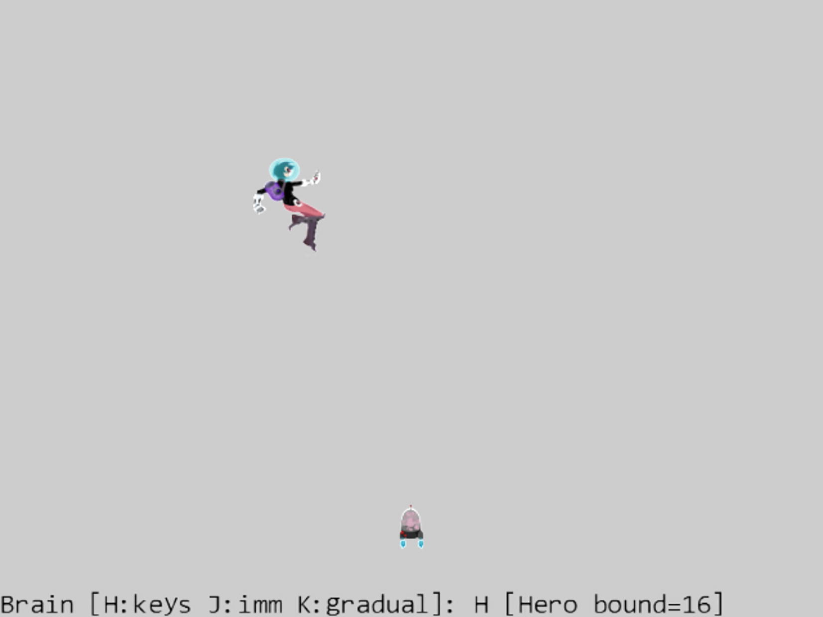
Test Bounding Boxes with MyGame
In the switch statement’s J and K cases, the modification tests for bounding box collision between the Brain and Hero objects before invoking Brain.rotateObjPointTo() and update() to cause the chasing behavior. In this way, the Brain object will stop moving as soon as it touches the bound of the Hero object. In addition, the collision results between the Hero object and 80 percent of the camera WC window are computed and displayed.
Observation
You can now run the project and observe that the Brain object, when in autonomous mode (J or K keys), stops moving as soon as it touches the Hero object. When you move the Hero object around, observe the Hero bound output message begins to echo WC window collisions before the Hero object actually touches the WC window bounds. This is a result of the 0.8, or 80 percent, parameter passed to the mCamera.collideWCBound() function , configuring the collision computation to 80 percent of the current WC window size. When the Hero object is completely within 80 percent of the WC window bounds, the output Hero bound value is 16 or the value of eboundcollideStatus.eInside. Try moving the Hero object to touch the top 20 percent of the window bound, and observe the Hero bound value of 4 or the value of eboundcollideStatus.eCollideTop. Now move the Hero object toward the top-left corner of the window, and observe the Hero bound value of 5 or eboundcollideStatus.eCollideTop | eboundcollideStatus.eCollideLeft. In this way, the collision status is a bitwise-or result of all the colliding bounds.
Per-Pixel Collisions
In the previous example, you saw the results of bounding box collision approximation. Namely, the Brain object’s motion stops as soon as its bounds overlap that of the Hero object. This is much improved over the original situation where the Brain object never stops moving. However, as illustrated in Figure 6-14 , there are two serious limitations to the bounding box–based collisions.
- 1.
The BoundingBox object introduced in the previous example does not account for rotation. This is a well-known limitation for AABB: although the approach is computationally efficient, it does not support rotated objects.
- 2.
The two objects do not actually collide. The fact that the bounds of two objects overlap does not automatically equate to the two objects colliding.
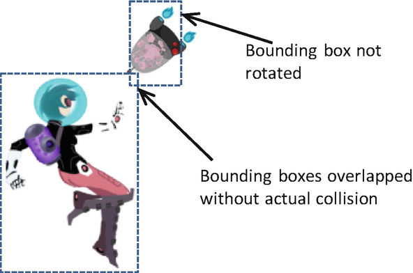
Limitation with bounding box–based collision
In this project, you will implement per-pixel-accurate collision detection, pixel-accurate collision detection, or per-pixel collision detection, to detect the overlapping of nontransparent pixels of two colliding objects. However, keep in mind that this is not an end-all solution. While the per-pixel collision detection is precise, the trade-off is potential performance costs. As an image becomes larger and more complex, it also has more pixels that need to be checked for collisions. This is in contrast to the constant computation cost required for bounding box collision detection.
The Per-Pixel Collisions Project

Running the Per-Pixel Collisions project
Arrow keys: Move the small textured object, the Portal minion
WASD keys: Move the large textured object, the Collector minion
To demonstrate how to detect nontransparent pixel overlap
To understand the pros and cons of using per-pixel-accurate collision detection
A “transparent” pixel is one you can see through completely and, in the case of this engine, has an alpha value of 0. A “nontransparent” pixel has a greater than 0 alpha value, or the pixel does not completely block what is behind it; it may or may not occlude. An “opaque” pixel occludes what is behind it, is “nontransparent,” and has an alpha value of 1. For example, notice that you can “see through” the top region of the Portal object. These pixels are nontransparent but not opaque and should cause a collision when an overlap occurs based on the parameters defined by the project.
You can find the following external resources in the assets folder: the fonts folder that contains the default system fonts, minion_collector.png, minion_portal.png, and minion_sprite.png. Note that minion_collector.png is a large, 1024x1024 image, while minion_portal.png is a small, 64x64 image; minion_sprite.png defines the DyePack sprite element.
Overview of Per-Pixel Collision Algorithm
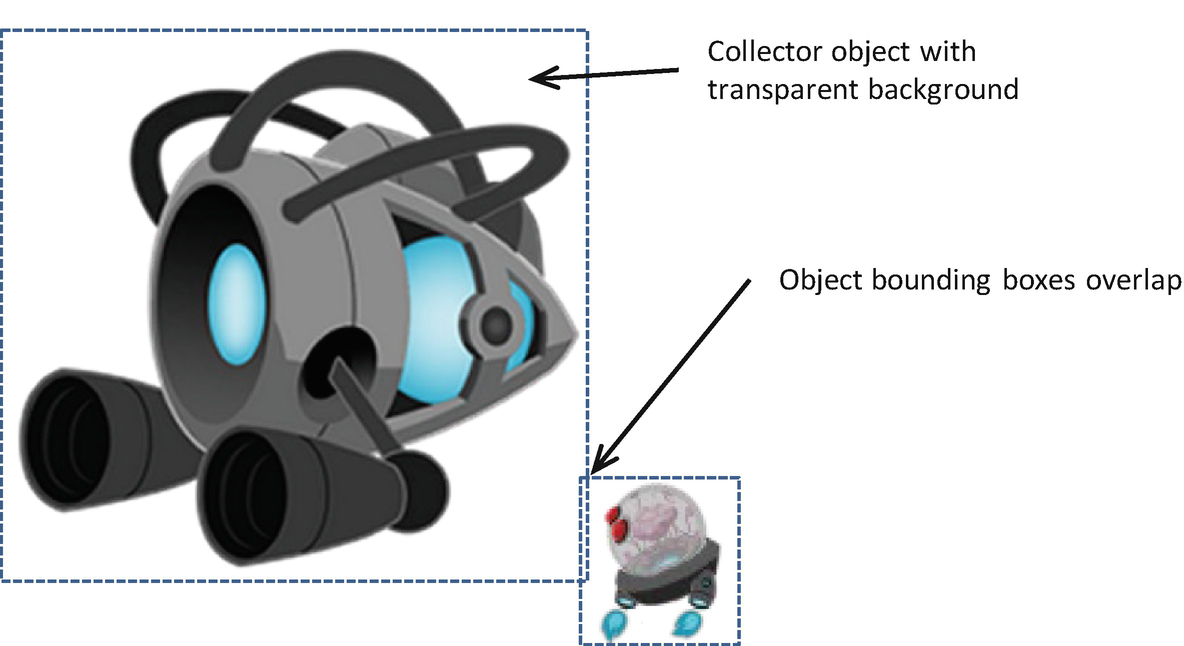
Overlapping bounding boxes without actual collision
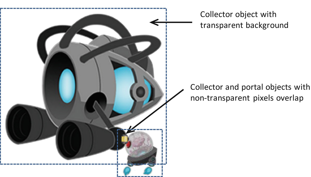
Pixel collision occurring between the large texture and the small texture
The per-pixel transformation to Image-B space from pixelCameraSpace is required because collision checking must be carried out within the same coordinate space.
Notice that in the algorithm Image-A and Image-B are exchangeable. That is, when testing for collision between two images, it does not matter which image is Image-A or Image-B. The collision result will be the same. Either the two images do overlap, or they do not. Additionally, pay attention to the runtime of this algorithm. Each pixel within Image-A must be processed; thus, the runtime is O(N), where N is the number of pixels in Image-A or Image-A’s resolution. For this reason, for performance reason, it is important to choose the smaller of the two images (the Portal minion in this case) as Image-A.
At this point, you can probably see why the performance of pixel-accurate collision detection is concerning. Checking for these collisions during every update with many high-resolution textures can quickly bog down performance. You are now ready to examine the implementation of per-pixel-accurate collision.
Modify Texture to Load a Texture as an Array of Colors
- 1.
In the texture.js file, expand the TextureInfo object to include a new variable for storing the color array of a file texture:
- 2.
Define and export a function to retrieve the color array from the GPU memory:
The getColorArray() function creates a WebGL FRAMEBUFFER, fills the buffer with the desired texture, and retrieves the buffer content into the CPU memory referenced by texInfo.mColorArray .
Modify TextureRenderable to Support Per-Pixel Collision
The TextureRenderable is the most appropriate class for implementing the per-pixel collision functionality. This is because TextureRenderable is the base class for all classes that render textures. Implementation in this base class means all subclasses can inherit the functionality with minimal additional changes.
As the functionality of the TextureRenderable class increases, so will the complexity and size of the implementation source code. For readability and expandability, it is important to maintain the size of source code files. An effective approach is to separate the source code of a class into multiple files according to their functionality.
Organize the Source Code
- 1.
Rename texture_renderable.js.to texture_renderable_main.js. This file defines the basic functionality of the TextureRenderable class.
- 2.
Create a new file in src/engine/renderables and name it texture_renderable_pixel_collision.js. This file will be used to extend the TextureRenderable class functionality in supporting per-pixel-accurate collision. Add in the following code to import from the Texture module and the basic TextureRenderable class, and reexport the TextureRenderable class. For now, this file does not serve any purpose; you will add in the appropriate extending functions in the following subsection.
- 3.
Create a new texture_renderable.js file to serve as the TextureRenderable access point by adding the following code:
With this structure, the texture_renderable_main.js file implements all the basic functionality and exports to texture_renderable_pixel_collision.js, which appends additional functionality to the TextureRenderable class. Finally, texture_renderable.js imports the extended functions from texture_renderable_pixel_collision.js. The users of the TextureRenderable class can simply import from texture_renderable.js and will have access to all of the defined functionality.
In this way, from the perspective of the game developer, texture_renderable.js serves as the access point to the TextureRenderable class and hides the details of the implementation source code structure. At the same time, from the perspective of you as the engine developer, complex implementations are separated into source code files with names indicating the content achieving readability of each individual file.
Define Access to the Texture Color Array
- 1.
Edit the texture_renderable_main.js file, and modify the constructor to add instance variables to hold texture information, including a reference to the retrieved color array, for supporting per-pixel collision detection and for later subclass overrides:
- 2.
Modify the setTexture() function to initialize the instance variables accordingly:
Note that by default, the mColorArry is initialized to null. For CPU memory optimization, the color array is fetched from the GPU only for textures that participate in per-pixel collision. The mElmWidthPixels and mElmHeightPixels variables are the width and height of the texture. These variables are defined for later subclass overrides such that the algorithm can support the collision of sprite elements.
Implement Per-Pixel Collision
- 1.
Edit the texture_renderable_pixel_collision.js file, and define a new function for the TextureRenderable class to set the mColorArray:
JavaScript classes are implemented based on prototype chains. After class construction, instance methods can be accessed and defined via the prototype of the class or aClass.prototype.method. For more information on JavaScript classes and prototypes, please refer to https://developer.mozilla.org/en-US/docs/Web/JavaScript/Inheritance_and_the_prototype_chain.
- 2.
Define a new function to return the alpha value, or the transparency, of any given pixel (x, y):
- 3.
Define a function to compute the WC position (returnWCPos) of a given pixel (i, j):
- 4.
Now, implement the inverse of the previous function, and use a WC position (wcPos) to compute the texture pixel indices (returnIndex):
- 5.
Now it is possible to implement the outlined per-pixel collision algorithm:
The parameter other is a reference to the other TextureRenderable object that is being tested for collision. If pixels do overlap between the objects, the returned value of wcTouchPos is the first detected colliding position in the WC space. Notice that the nested loops terminate as soon as one-pixel overlap is detected or when pixelTouch becomes true. This is an important feature for efficiency concerns. However, this also means that the returned wcTouchPos is simply one of the many potentially colliding points.
Support Per-Pixel Collision in GameObject
This function checks to ensure that the objects are colliding and delegates the actual per-pixel collision to the TextureRenderable objects. Notice the intersectsBound() function for a bounding box intersection check before invoking the potentially expensive TextureRenderable.pixelTouches() function .
Test the Per-Pixel Collision in MyGame
As illustrated in Figure 6-15, the testing of per-pixel collision is rather straightforward, involving three instances of GameObject: the large Collector minion, the small Portal minion, and the DyePack. The Collector and Portal minions are controlled by the arrow and WASD keys, respectively. The details of the implementation of MyGame are similar to the previous projects and are not shown.
Observation
You can now test the collision accuracy by moving the two minions and intersecting them at different locations (e.g., top colliding with the bottom, left colliding with the right) or moving them such that there are large overlapping areas. Notice that it is rather difficult, if not impossible, to predict the actual reported intersection position (position of the DyePack). It is important to remember that the per-pixel collision function is mainly a function that returns true or false indicating whether there is a collision. You cannot rely on this function to compute the actual collision positions.
Lastly, try switching to calling the Collector.pixelTouches() function to detect collisions. Notice the less than real-time performance! In this case, the computation cost of the Collector.pixelTouches() function is 16×16=256 times that of the Portal.pixelTouches() function .
Generalized Per-Pixel Collisions
In the previous section, you saw the basic operations required to achieve per-pixel-accurate collision detection. However, as you may have noticed, the previous project applies only when the textures are aligned along the x/y axes. This means that your implementation does not support collisions between rotated objects.
This section explains how you can achieve per-pixel-accurate collision detection when objects are rotated. The fundamental concepts of this project are the same as in the previous project; however, this version involves working with vector decomposition, and a quick review can be helpful.
Vector Review: Components and Decomposition
 : the normalized component vectors
  and
and  decompose the vector
  into the components
  and
and  .
.
The decomposition of vector 
 and
and  and any vector
  , the following formulae are always true:

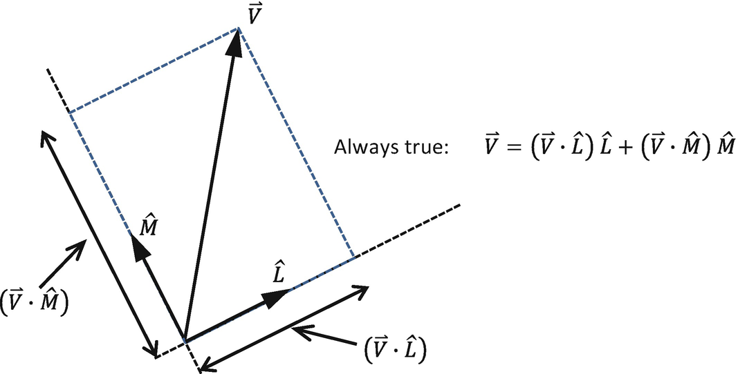
Decomposing a vector by two normalized component vectors
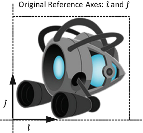
An axes-aligned texture
 and
and  , as shown in Figure 6-21.

A rotated texture and its component vectors
The General Pixel Collisions Project

Running the General Pixel Collisions project
Arrow keys: Move the small textured object, the Portal minion
P key: Rotates the small textured object, the Portal minion
WASD keys: Move the large textured object, the Collector minion
E key: Rotates the large textured object, the Collector minion
To access pixels of a rotated image via vector decomposition
To support per-pixel-accurate collision detection between two rotated textured objects
You can find the same external resource files as in the previous project in the assets folder.
Modify Pixel Collision to Support Rotation
- 1.
Edit the texture_renderable_pixel_collision.js file and modify the _indexToWCPosition() function :
 and
and  normalized component vectors. The variables xDisp and yDisp are the displacements to be offset along xDir and yDir, respectively. The returned value of returnWCPos is a simple displacement from the object’s center position along the xDirDisp and yDirDisp vectors. Note that xDirDisp and yDirDisp are the scaled xDir and yDir vectors.
- 2.
In a similar fashion, modify the _wcPositionToIndex() function to support the rotated normalized vector components:
- 3.
The pixelTouches() function needs to be modified to compute the rotated normalized component vectors:
The variables xDir and yDir are the rotated normalized component vectors  and
and  of this TextureRenderable object, while otherXDir and otherYDir are those of the colliding object. These vectors are used as references for computing transformations from texture index to WC and from WC to texture index.
Modify GameObject to Support Rotation
The listed code shows that if either of the colliding objects is rotated, then two encompassing circles are used to determine whether the objects are sufficiently close for the expensive per-pixel collision computation. The two circles are defined with radii equal to the hypotenuse of the x/y size of the corresponding TextureRenderable objects. The per-pixel collision detection is invoked only if the distance between these two circles is less than the sum of the radii.
Test Generalized Per-Pixel Collision
The code for testing the rotated TextureRenderable objects is essentially identical to that from the previous project, with the exception of the two added controls for rotations. The details of the implementation are not shown. You can now run the project, rotate the two objects, and observe the accurate collision results.
Per-Pixel Collisions for Sprites
The previous project implicitly assumes that the Renderable object is covered by the entire texture map. This assumption means that the per-pixel collision implementation does not support sprite or animated sprite objects. In this section, you will remedy this deficiency.
The Sprite Pixel Collisions Project

Running the Sprite Pixel Collisions project
Arrow and P keys: Move and rotate the Portal minion
WASD keys: Move the Hero
L, R, H, B keys: Select the target for colliding with the Portal minion
To generalize the per-pixel collision implementation for sprite and animated sprite objects
You can find the following external resource files in the assets folder: the fonts folder that contains the default system fonts, minion_sprite.png, and minion_portal.png.
Implement Per-Pixel Collision for SpriteRenderable
- 1.
Modify the SpriteRenderable constructor to call the _setTexInfo() function to initialize per-pixel collision parameters; this function is defined in the next step:
- 2.
Define the _setTexInfo() function to override instance variables defined in the TextureRenderable superclass. Instead of the entire texture image, the instance variables now identify the currently active sprite element.
- 3.
Remember to call the _setTexInfo() function when the current sprite element is updated in the setElementUVCoordinate() and setElementPixelPositions() functions:
Support Accesses to Sprite Pixels in TextureRenderable
Test Per-Pixel Collision for Sprites in MyGame
Portal minion: A simple TextureRenderable object
Hero and Brain: SpriteRenderable objects where the textures shown on the geometries are sprite elements defined in the minion_sprite.png sprite sheet
Left and Right minions: SpriteAnimateRenderable objects with sprite elements defined in the top two rows of the minion_sprite.pnganimated sprite sheet
Observation
- 1.
Try moving the Hero object and observe how the Brain object constantly seeks out and collides with it. This is the case of collision between two SpriteRenderable objects.
- 2.
Press the L/R keys and then move the Portal minion with the WASD keys to collide with the Left or Right minions. Remember that you can rotate the Portal minion with the P key. This is the case of collision between TextureRenderable and SpriteAnimatedRenderable objects.
- 3.
Press the H key and then move the Portal minion to collide with the Hero object. This is the case of collision between TextureRenderable and SpriteRenderable objects.
- 4.
Press the B key and then move the Portal minion to collide with the Brain object. This is the case of collision between rotated TextureRenderable and SpriteRenderable objects .
Summary
This chapter showed you how to encapsulate common behaviors of objects in games and demonstrated the benefits of the encapsulation in the forms of a simpler and better organized control logic in the client’s MyGame test levels. You reviewed vectors in 2D space. A vector is defined by its direction and magnitude. Vectors are convenient for describing displacements (velocities). You reviewed some foundational vector operations, including normalization of a vector and how to calculate both dot and cross products. You worked with these operators to implement the front-facing direction capability and create simple autonomous behaviors such as pointing toward a specific object and chasing.
The need for detecting object collisions became a prominent omission as the behaviors of objects increased in sophistication. The axis-aligned bounding boxes, or AABBs, were introduced as a crude, yet computationally efficient solution for approximating object collisions. You learned the algorithm for per-pixel-accurate collision detection and that its accuracy comes at the cost of performance. You now understand how to mitigate the computational cost in two ways. First, you invoke the pixel-accurate procedure only when the objects are sufficiently close to each other, such as when their bounding boxes collide. Second, you invoke the pixel iteration process based on the texture with a lower resolution.
When implementing pixel-accurate collision, you began with tackling the basic case of working with axis-aligned textures. After that implementation, you went back and added support for collision detection between rotated textures. Finally, you generalized the implementation to support collisions between sprite elements. Solving the easiest case first lets you test and observe the results and helps define what you might need for the more advanced problems (rotation and subregions of a texture in this case).
At the beginning of this chapter, your game engine supported interesting sophistication in drawing ranging from the abilities to define WC space, to view the WC space with the Camera object, and to draw visually pleasing textures and animations on objects. However, there was no infrastructure for supporting the behaviors of the objects. This shortcoming resulted in clustering of initialization and control logic in the client-level implementations. With the object behavior abstraction, mathematics, and collision algorithms introduced and implemented in this chapter, your game engine functionality is now better balanced. The clients of your game engine now have tools for encapsulating specific behaviors and detecting collisions. The next chapter reexamines and enhances the functionality of the Camera object. You will learn to control and manipulate the Camera object and work with multiple Camera objects in the same game.
Game Design Considerations
Chapters 1–5 introduced foundation techniques for drawing, moving, and animating objects on the screen. The Scene Objects project from Chapter 4 described a simple interaction behavior and showed you how to change the game screen based on the location of a rectangle: recall that moving the rectangle to the left boundary caused the level to visually change, while the Audio Support project added contextual sound to reinforce the overall sense of presence. Although it’s possible to build an intriguing (albeit simple) puzzle game using only the elements from Chapters 1 to 5, things get much more interesting when you can integrate object detection and collision triggers; these behaviors form the basis for many common game mechanics and provide opportunities to design a wide range of interesting gameplay scenarios.
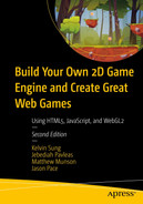
Starting with the Game Objects project, you can see how the screen elements start working together to convey the game setting; even with the interaction in this project limited to character movement, the setting is beginning to resolve into something that conveys a sense of place. The hero character appears to be flying through a moving scene populated by a number of mechanized robots, and there’s a small object in the center of the screen that you might imagine could become some kind of special pickup.
Even at this basic stage of development it’s possible to brainstorm game mechanics that could potentially form the foundation for a full game. If you were designing a simple game mechanic based on only the screen elements found in the Game Objects project, what kind of behaviors would you choose and what kind of actions would you require the player to perform? As one example, imagine that the hero character must avoid colliding with the flying robots and that perhaps some of the robots will detect and pursue the hero in an attempt to stop the player’s progress; maybe the hero is also penalized in some way if they come into contact with a robot. Imagine perhaps that the small object in the center of the screen allows the hero to be invincible for a fixed period of time and that we’ve designed the level to require temporary invincibility to reach the goal, thus creating a more complex and interesting game loop (e.g., avoid the pursuing robots to reach the power up, activate the power up and become temporarily invincible, use invincibility to reach the goal). With these few basic interactions, we’ve opened opportunities to explore mechanics and level designs that will feel very familiar from many different kinds of games, all with just the inclusion of the object detection, chase, and collision behaviors covered in Chapter 6. Try this design exercise yourself using just the elements shown in the Game Objects project: What kinds of simple conditions and behaviors might you design to make your experience unique? How many ways can you think of to use the small object in the center of the screen? The final design project in Chapter 12 will explore these themes in greater detail.
This is also a good opportunity to brainstorm some of the other nine elements of game design discussed in Chapter 1. What if the game wasn’t set in space with robots? Perhaps the setting is in a forest, or under water, or even something completely abstract. How might you incorporate audio to enhance the sense of presence and reinforce the game setting? You’ll probably be surprised by the variety of settings and scenarios you come up with. Limiting yourself to just the elements and interactions covered through Chapter 6 is actually a beneficial exercise as design constraints often help the creative process by shaping and guiding your ideas. Even the most advanced video games typically have a fairly basic set of core game loops as their foundation.
The Vectors: Front and Chase project is interesting from both a game mechanic and presence perspective. Many games, of course, require objects in the game world to detect the hero character and will either chase or try to avoid the player (or both if the object has multiple states). The project also demonstrates two different approaches to chase behavior, instant and smooth pursuit, and the game setting will typically influence which behavior you choose to implement. The choice between instant and smooth pursuit is a great example of subtle behaviors that can significantly influence the sense of presence. If you were designing a game where ships were interacting on the ocean, for example, you would likely want their pursuit behavior to take real-world inertia and momentum into consideration because ships can’t instantly turn and respond to changes in movement; rather, they move smoothly and gradually, demonstrating a noticeable delay in how quickly they can respond to a moving target. Most objects in the physical world will display the same inertial and momentum constraint to some degree, but there are also situations where you may want game objects to respond directly to path changes (or, perhaps, you want to intentionally flout real-world physics and create a behavior that isn’t based on the limitations of physical objects). The key is to always be intentional about your design choices, and it’s good to remember that virtually no implementation details are too small to be noticed by players.
The Bounding Box and Collisions project introduces the key element of detection to your design arsenal, allowing you to begin including more robust cause-and-effect mechanics that form the basis for many game interactions. Chapter 6 discusses the trade-offs of choosing between the less precise but more performant bounding box collision detection method and the precise but resource-intensive per-pixel detection method. There are many situations where the bounding-box approach is sufficient, but if players perceive collisions to be arbitrary because the bounding boxes are too different from the actual visual objects, it can negatively impact the sense of presence. Detection and collision are even more powerful design tools when coupled with the result from the Per-Pixel Collisions project. Although the dye pack in this example was used to indicate the first point of collision, you can imagine building interesting causal chains around a new object being produced as the result of two objects colliding (e.g., player pursues object, player collides with object, object “drops” a new object that enables the player to do something they couldn’t do before). Game objects that move around the game screen will typically be animated, of course, so the Sprite Pixel Collisions project describes how to implement collision detection when the object boundaries aren’t stationary.
With the addition of the techniques in Chapter 6, you now have a critical mass of behaviors that can be combined to create truly interesting game mechanics covering the spectrum from action games to puzzlers. Of course, game mechanic behaviors are only one of the nine elements of game design and typically aren’t sufficient on their own to create a magical gameplay experience: the setting, visual style, meta-game elements, and the like all have something important to contribute. The good news is that creating a memorable game experience need not be as elaborate as you often believe and great games continue being produced based on relatively basic combinations of the behaviors and techniques covered in Chapters 1–6. The games that often shine the brightest aren’t always the most complex, but rather they’re often the games where every aspect of each of the nine elements of design is intentional and working together in harmony. If you give the appropriate attention and focus to all aspects of the game design, you’re on a great track to produce something great whether you’re working on your own or you’re part of a large team.