Use any image or photograph as a texture representing characters or objects in your game
Understand and use texture coordinates to identify a location on an image
Optimize texture memory utilization by combining multiple characters and objects into one image
Produce and control animations using sprite sheets
Display texts of different fonts and sizes anywhere in your game
Introduction
Custom-composed images are used to represent almost all objects including characters, backgrounds, and even animations in most 2D games. For this reason, the proper support of image operations is core to 2D game engines. A game typically works with an image in three distinct stages: loading, rendering, and unloading.
Loading is the reading of the image from the hard drive of the web server into the client’s system main memory, where it is processed and stored in the graphics subsystem. Rendering occurs during gameplay when the loaded image is drawn continuously to represent the respective game objects. Unloading happens when an image is no longer required by the game and the associated resources are reclaimed for future uses. Because of the slower response time of the hard drive and the potentially large amount of data that must be transferred and processed, loading images can take a noticeable amount of time. This, together with the fact that, just like the objects that images represent, the usefulness of an image is usually associated with individual game level, image loading and unloading operations typically occur during game-level transitions. To optimize the number of loading and unloading operations, it is a common practice to combine multiple lower-resolution images into a single larger image. This larger image is referred to as a sprite sheet .
To represent objects, images with meaningful drawings are pasted, or mapped, on simple geometries. For example, a horse in a game can be represented by a square that is mapped with an image of a horse. In this way, a game developer can manipulate the transformation of the square to control the horse. This mapping of images on geometries is referred to as texture mapping in computer graphics.
The illusion of movement, or animation, can be created by cycling through strategically mapping selected images on the same geometry. For example, during subsequent game loop updates, different images of the same horse with strategically drawn leg positions can be mapped on the same square to create the illusion that the horse is galloping. Usually, these images of different animated positions are stored in one sprite sheet or an animated sprite sheet. The process of sequencing through these images to create animation is referred to as sprite animation or sprite sheet animation.
This chapter first introduces you to the concept of texture coordinates such that you can understand and program with the WebGL texture mapping interface. You will then build a core texture component and the associated classes to support mapping with simple textures, working with sprite sheets that contain multiple objects, creating and controlling motions with animated sprite sheets, and extracting alphabet characters from a sprite sheet to display text messages.
A texture is an image that is loaded into the graphics system and ready to be mapped onto a geometry. When discussing the process of texture mapping, “an image” and “a texture” are often used interchangeably. A pixel is a color location in an image and a texel is a color location in a texture.
Texture Mapping and Texture Coordinates
As discussed, texture mapping is the process of pasting an image on a geometry, just like putting a sticker on an object. In the case of your game engine, instead of drawing a constant color for each pixel occupied by the unit square, you will create GLSL shaders to strategically select texels from the texture and display the corresponding texel colors at the screen pixel locations covered by the unit square. The process of selecting a texel, or converting a group of texels into a single color, to be displayed to a screen pixel location is referred to as texture sampling. To render a texture-mapped pixel, the texture must be sampled to extract a corresponding texel color.
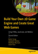
The Texture Coordinate System and the corresponding uv values defined for all images
There are conventions that define the v axis increasing either upward or downward. In all examples of this book, you will program WebGL to follow the convention in Figure 5-1, with the v axis increasing upward.

Defining Texture Space uv values to map the entire image onto the geometry in Model Space
The Texture Shaders Project

Running the Texture Shaders project with both scenes
The controls of the project are as follows, for both scenes:
Right-arrow key: Moves the middle rectangle toward the right. If this rectangle passes the right window boundary, it will be wrapped to the left side of the window.
Left-arrow key: Moves the middle rectangle toward the left. If this rectangle crosses the left window boundary, the game will transition to the next scene.
To demonstrate how to define uv coordinates for geometries with WebGL
To create a texture coordinate buffer in the graphics system with WebGL
To build GLSL shaders to render the textured geometry
To define the Texture core engine component to load and process an image into a texture and to unload a texture
To implement simple texture tinting, a modification of all texels with a programmer-specified color
You can find the following external resource files in the assets folder: a scene-level file (blue_level.xml) and four images (minion_collector.jpg, minion_collector.png, minion_portal.jpg, and minion_portal.png).
Overview
texture_vs.glsl and texture_fs.glsl: These are new files created to define GLSL shaders for supporting drawing with uv coordinates. Recall that the GLSL shaders must be loaded into WebGL and compiled during the initialization of the game engine.
vertex_buffer.js: This file is modified to create a corresponding uv coordinate buffer to define the texture coordinate for the vertices of the unit square.
texture_shader.js : This is a new file that defines TextureShader as a subclass of SimpleShader to interface the game engine with the corresponding GLSL shaders (TextureVS and TextureFS).
texture_renderable.js: This is a new file that defines TextureRenderable as a subclass of Renderable to facilitate the creation, manipulation, and drawing of multiple instances of textured objects.
shader_resources.js : Recall that this file defines a single instance of SimpleShader to wrap over the corresponding GLSL shaders to be shared system wide by all instances of Renderable objects. In a similar manner, this file is modified to define an instance of TextureShader to be shared by all instances of TextureRenderable objects.
gl.js: This file is modified to configure WebGL to support drawing with texture maps.
texture.js : This is a new file that defines the core engine component that is capable of loading, activating (for rendering), and unloading texture images.
my_game.js and blue_level.js: These game engine client files are modified to test the new texture mapping functionality.
Two new source code folders, src/engine/shaders and src/engine/renderables, are created for organizing the engine source code. These folders are created in anticipation of the many new shader and renderer types required to support the corresponding texture-related functionality. Once again, continuous source code reorganization is important in supporting the corresponding increase in complexity. A systematic and logical source code structure is critical in maintaining and expanding the functionality of large software systems.
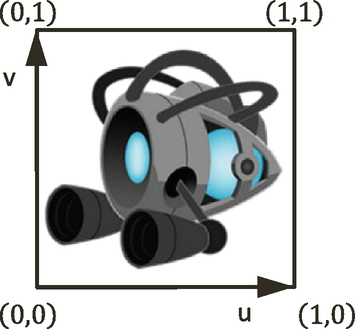
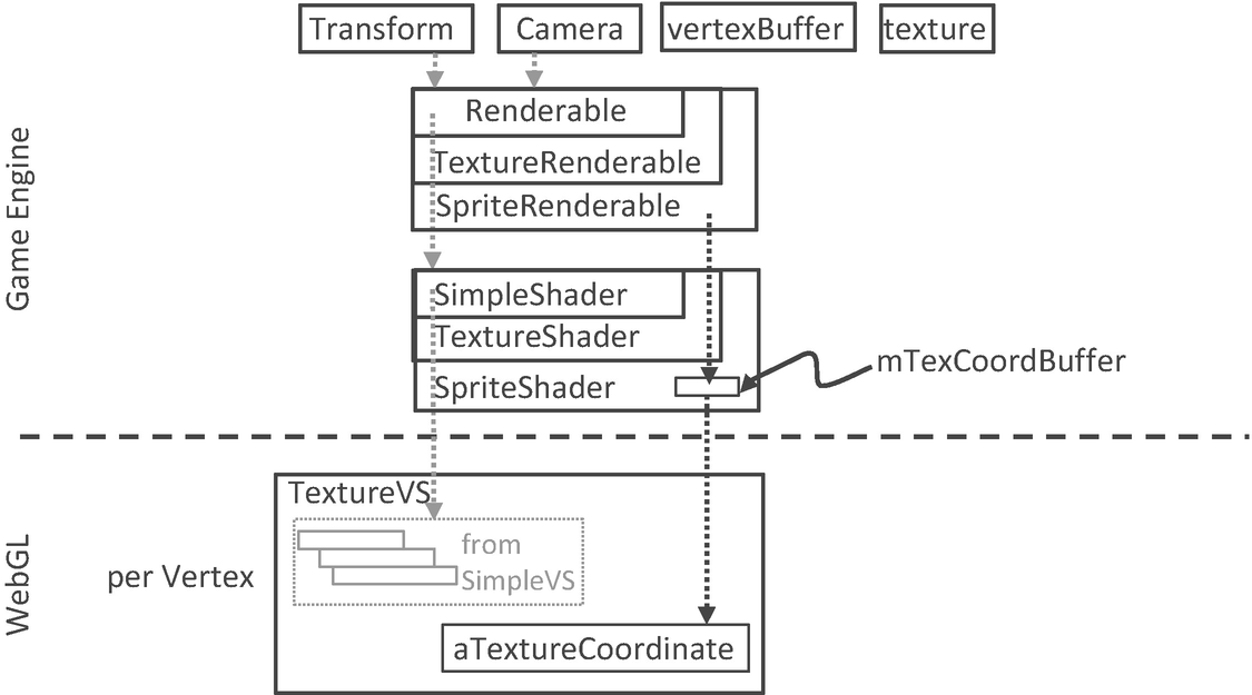
Extension of SimpleShader/Renderable Architecture
The SimpleShader and Renderable architecture
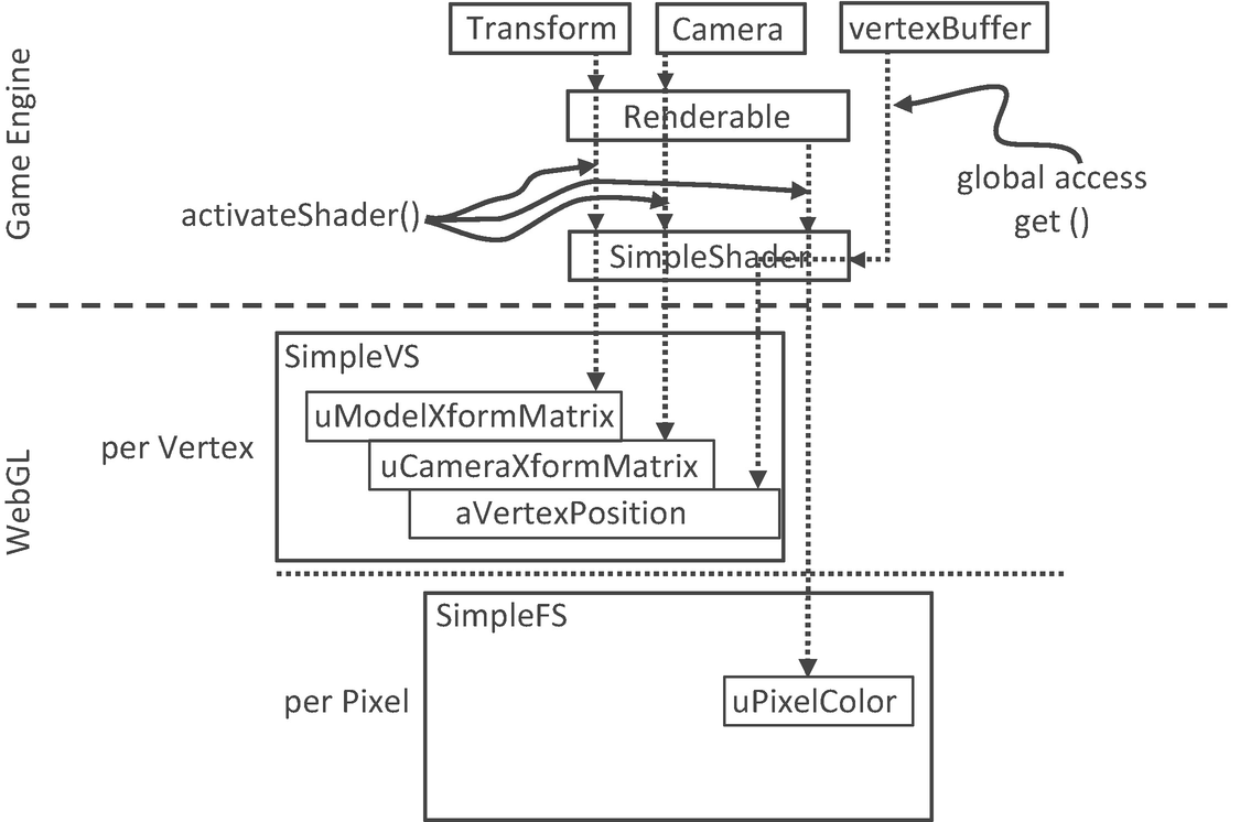
The TextureVS/FS GLSL shaders and the corresponding TextureShader/TextureRenderable object pair
GLSL Texture Shader
- 1.
Create a new file in the src/glsl_shaders folder and name it texture_vs.glsl.
- 2.
Add the following code to the texture_vs.glsl file:
- a.
The first additional line adds the aTextureCoordinate attribute . This defines a vertex to include a vec3 (aVertexPosition, the xyz position of the vertex) and a vec2 (aTextureCoordinate, the uv coordinate of the vertex).
- b.
The second declares the varying vTexCoord variable. The varying keyword in GLSL signifies that the associated variable will be linearly interpolated and passed to the fragment shader. As explained earlier and illustrated in Figure 5-2, uv values are defined only at vertex positions. In this case, the varying vTexCoord variable instructs the graphics hardware to linearly interpolate the uv values to compute the texture coordinate for each invocation of the fragment shader.
- c.
The third and final line assigns the vertex uv coordinate values to the varying variable for interpolation and forwarding to the fragment shader.
- 1.
Create a new file in the src/glsl_shaders folder and name it texture_fs.glsl.
- 2.
Add the following code to the texture_fs.glsl file to declare the variables. The sampler2D data type is a GLSL utility that is capable of reading texel values from a 2D texture. In this case, the uSampler object will be bound to a GLSL texture such that texel values can be sampled for every pixel rendered. The uPixelColor is the same as the one from SimpleFS. The vTexCoord is the interpolated uv coordinate value for each pixel.
- 3.
Add the following code to compute the color for each pixel:
The texture2D() function samples and reads the texel value from the texture that is associated with uSampler using the interpolated uv values from vTexCoord. In this example, the texel color is modified, or tinted, by a weighted sum of the color value defined in uPixelColor according to the transparency or the value of the corresponding alpha channel. In general, there is no agreed-upon definition for tinting texture colors. You are free to experiment with different ways to combine uPixelColor and the sampled texel color. For example, you can try multiplying the two. In the provided source code file, a few alternatives are suggested. Please do experiment with them.
Define and Set Up Texture Coordinates
- 1.
Modify vertex_buffer.js to define both xy and uv coordinates for the unit square. As illustrated in Figure 5-2, the mTextureCoordinates variable defines the uv values for the corresponding four xy values of the unit square defined sequentially in mVerticesOfSquare. For example, (1, 1) are the uv values associated with the (0.5, 0.5, 0) xy position, (0, 1) for (-0.5, 0.5, 0), and so on.
- 2.
Define the variable, mGLTextureCoordBuffer, to keep a reference to the WebGL buffer storage for the texture coordinate values of mTextureCoordinates and the corresponding getter function:
- 3.
Modify the init() function to include a step D to initialize the texture coordinates as a WebGL buffer. Notice the initialization process is identical to that of the vertex xy coordinates except that the reference to the new buffer is stored in mGLTextureCoordBuffer and the transferred data are the uv coordinate values.
- 4.
Remember to release the allocated buffer during final cleanup:
- 5.
Finally, remember to export the changes:
Interface GLSL Shader to the Engine
- 1.
Create a new folder called shaders in src/engine. Move the simple_shader.js file into this folder, and do not forget to update the reference path in index.js.
- 2.
Create a new file in the src/engine/shaders folder and name it texture_shader.js .
In the listed code, take note of the following:
- a.
The defined TextureShader class is an extension, or subclass, to the SimpleShader class.
- b.
The constructor implementation first calls super(), the constructor of SimpleShader. Recall that the SimpleShader constructor will load and compile the GLSL shaders defined by the vertexShaderPath and fragmentShaderPath parameters and set mVertexPositionRef to reference the aVertexPosition attribute defined in the shader.
- c.
In the rest of the constructor, the mTextureCoordinateRef keeps a reference to the aTextureCoordinate attribute defined in the texture_vs.glsl.
- d.
In this way, both the vertex position (aVertexPosition) and texture coordinate (aTextureCoordinate) attributes are referenced by a JavaScript TextureShader object.
- 3.
Override the activate() function to enable the texture coordinate data. The superclass super.activate() function sets up the xy vertex position and passes the values of pixelColor, trsMatrix, and cameraMatrix to the shader. The rest of the code binds mTextureCoordinateRef, the texture coordinate buffer defined in the vertex_buffer module, to the aTextureCoordinate attribute in the GLSL shader and mSampler to texture unit 0 (to be detailed later).
With the combined functionality of SimpleShader and TextureShader, after the activate() function call, both of the attribute variables (aVertexPosition and aTextureCoordinate) in the GLSL texture_vs shader are connected to the corresponding buffers in the WebGL memory.
Facilitate Sharing with shader_resources
- 1.
In shader_resources.js, add the variables to hold a texture shader:
- 2.
Define a function to retrieve the texture shader:
- 3.
Create the instance of texture shader in the createShaders() function:
- 4.
Modify the init() function to append the loadPromise to include the loading of the texture shader source files:
- 5.
Remember to release newly allocated resources during cleanup:
- 6.
Lastly, remember to export the newly defined functionality:
TextureRenderable Class
Just as the Renderable class encapsulates and facilitates the definition and drawing of multiple instances of SimpleShader objects, a corresponding TextureRenderable class needs to be defined to support the drawing of multiple instances of TextureShader objects.
Changes to the Renderable Class
- 1.
Create the src/engine/renderables folder and move renderable.js into this folder. Remember to update index.js to reflect the file location change.
- 2.
Define the _setShader() function to set the shader for the Renderable. This is a protected function which allows subclasses to modify the mShader variable to refer to the appropriate shaders for each corresponding subclass.
Functions with names that begin with “_” are either private or protected and should not be called from outside of the class. This is a convention followed in this book and not enforced by JavaScript.
Define the TextureRenderable Class
- 1.
Create a new file in the src/engine/renderables folder and name it texture_renderable.js. Add the constructor. Recall that super() is a call to the superclass (Renderable) constructor; similarly, the super.setColor() and super._setShader() are calls to the superclass functions. As will be detailed when discussing the engine texture resource module, the myTexture parameter is the path to the file that contains the texture image.
- 2.
Define a draw() function to append the function defined in the Renderable class to support textures. The texture.activate() function activates and allows drawing with the specific texture. The details of this function will be discussed in the following section.
- 3.
Define a getter and setter for the texture reference:
- 4.
Finally, remember to export the class:
Texture Support in the Engine
To support drawing with textures, the rest of the game engine requires two main modifications: WebGL context configuration and a dedicated engine component to support operations associated with textures.
Configure WebGL to Support Textures
The parameter passed to mCanvas.getContext() informs the browser that the canvas should be opaque. This can speed up the drawing of transparent content and images. The blendFunc() function enables transparencies when drawing images with the alpha channel. The pixelStorei() function defines the origin of the uv coordinate to be at the lower-left corner.
Create the Texture Resource Module
- 1.
Create a new file in the src/engine/resources folder and name it texture.js. This file will implement the Texture engine component.
- 2.
Define the TextureInfo class to represent a texture in the game engine. The mWidth and mHeight are the pixel resolution of the texture image, and mGLTexID is a reference to the WebGL texture storage.
For efficiency reasons, many graphics hardware only supports texture with image resolutions that are in powers of 2, such as 2x4 (21x 22), or 4x16 (22x 24), or 64x256 (26x 28), and so on. This is also the case for WebGL. All examples in this book only work with textures with resolutions that are powers of 2.
- 3.
Import the core resource management functionality from the resource_map:
- 4.
Define a function to load an image asynchronously as a promise and push the promise to be part of the pending promises in the map. Distinct from the text and audio resources, JavaScript Image API supports straightforward image file loading, and the map.loadDecodeParse() is not required in this case. Once an image is loaded, it is passed to the processLoadedImage() function with its file path as the name.
- 5.
Add an unload() function to clean up the engine and release WebGL resources:
- 6.
Now define the processLoadedImage() function to convert the format of an image and store it to the WebGL context. The gl.createTexture() function creates a WebGL texture buffer and returns a unique ID. The texImage2D() function stores the image into the WebGL texture buffer, and generateMipmap() computes a mipmap for the texture. Lastly, a TextureInfo object is instantiated to refer to the WebGL texture and stored into the resource_map according to the file path to the texture image file.
A mipmap is a representation of the texture image that facilitates high-quality rendering. Please consult a computer graphics reference book to learn more about mipmap representation and the associated texture mapping algorithms.
- 7.
Define a function to activate a WebGL texture for drawing:
- a.
The get() function locates the TextureInfo object from the resource_map based on the textureName. The located mGLTexID is used in the bindTexture() function to activate the corresponding WebGL texture buffer for rendering.
- b.
The texParameteri() function defines the rendering behavior for the texture. The TEXTURE_WRAP_S/T parameters ensure that the texel values will not wrap around at the texture boundaries. The TEXTURE_MAG_FILTER parameter defines how to magnify a texture, in other words, when a low-resolution texture is rendered to many pixels in the game window. The TEXTURE_MIN_FILTER parameter defines how to minimize a texture, in other words, when a high-resolution texture is rendered to a small number of pixels.
- c.
The LINEAR and LINEAR_MIPMAP_LINEAR configurations generate smooth textures by blurring the details of the original images, while the commented out NEAREST option will result in unprocessed textures best suitable for pixelated effects. Notice that in this case, color boundaries of the texture image may appear jagged.
In general, it is best to use texture images with similar resolution as the number of pixels occupied by the objects in the game. For example, a square that occupies a 64x64 pixel space should ideally use a 64x64 texel texture.
- 8.
Define a function to deactivate a texture as follows. This function sets the WebGL context to a state of not working with any texture.
- 9.
Finally, remember to export the functionality:
Export New Functionality to the Client
Testing of Texture Mapping Functionality
With the described modifications, the game engine can now render constant color objects as well as objects with interesting and different types of textures. The following testing code is similar to that from the previous example where two scenes, MyGame and BlueLevel, are used to demonstrate the newly added texture mapping functionality. The main modifications include the loading and unloading of texture images and the creation and drawing of TextureRenderable objects. In addition, the MyGame scene highlights transparent texture maps with alpha channel using PNG images, and the BlueScene scene shows corresponding textures with images in the JPEG format.
As in all cases of building a game, it is essential to ensure that all external resources are properly organized. Recall that the assets folder is created specifically for the organization of external resources. Take note of the four new texture files located in the assets folder: minion_collector.jpg, minion_collector.png, minion_portal.jpg, and minion_portal.png.
Modify the BlueLevel Scene File to Support Textures
The TextureSquare element is similar to Square with the addition of a Texture attribute that specifies which image file should be used as a texture map for the square. Note that as implemented in texture_fs.glsl, the alpha value of the Color element is used for tinting the texture map. The XML scene description is meant to support slight tinting of the minion_portal.jpg texture and no tinting of the minion_collector.jpg texture. This texture tinting effect can be observed in the right image of Figure 5-3. In addition, notice that both images specified are in the JPEG format. Since the JPEG format does not support the storing of alpha channel, the unused regions of the two images show up as white areas outside the portal and collector minions in the right image of Figure 5-3.
Modify SceneFileParser
The scene file parser, scene_file_parser.js , is modified to support the parsing of the updated blue_scene.xml, in particular, to parse Square elements into Renderable objects and TextureSquare elements into TextureRenderable objects. For details of the changes, please refer to the source code file in the src/my_game/util folder.
Test BlueLevel with JPEGs
- 1.
Edit blue_level.js and modify the constructor to define constants to represent the texture images:
- 2.
Initiate loading of the textures in the load() function:
- 3.
Likewise, add code to clean up by unloading the textures in the unload() function :
- 4.
Support loading of the next scene with the next() function:
- 5.
Parse the textured squares in the init() function:
- 6.
Include appropriate code in the update() function to continuously change the tinting of the portal TextureRenderable, as follows:
- a.
Index 1 of mSqSet is the portal TextureRenderable object , and index 3 of the color array is the alpha channel.
- b.
The listed code continuously increases and wraps the alpha value of the mColor variable in the TextureRenderable object. Recall that the values of this variable are passed to TextureShader and then loaded to the uPixelColor of TextureFS for tinting the texture map results.
- c.
As defined in the first TextureSquare element in the blue_scene.xml file, the color defined for the portal object is red. For this reason, when running this project, in the blue level, the portal object appears to be blinking in red.
Test MyGame with PNGs
- 1.
Edit my_game.js; modify the MyGame constructor to define texture image files and the variables for referencing the TextureRenderable objects:
- 2.
Initiate the loading of the textures in the load() function:
- 3.
Make sure you remember to unload the textures in unload():
- 4.
Define the next() function to start the blue level:
- 5.
Create and initialize the TextureRenderables objects in the init() function :
- 6.
The modification to the draw() function draws the two new TextureRenderable objects by calling their corresponding draw() functions, while the modification to the update() function is similar to that of the BlueLevel discussed earlier. Please refer to the my_game.js source code file in the src/my_game folder for details.
When running the example for this project in the chapter5/5.1.texture_shaders folder, once again take note of the results of continuously changing the texture tinting—the blinking of the portal minion in red. In addition, notice the differences between the PNG-based textures in the MyGame level and the corresponding JPEG ones with white borders in the BlueLevel. It is visually more pleasing and accurate to represent objects using textures with the alpha (or transparency) channel. PNG is one of the most popular image formats that supports the alpha channel.
Observations
This project has been the longest and most complicated one that you have worked with. This is because working with texture mapping requires you to understand texture coordinates, the implementation cuts across many of the files in the engine, and the fact that actual images must be loaded, converted into textures, and stored/accessed via WebGL. To help summarize the changes, Figure 5-6 shows the game engine states in relation to the states of an image used for texture mapping and some of the main game engine operations.

Overview of the states of an image file and the corresponding WebGL texture
Drawing with Sprite Sheets
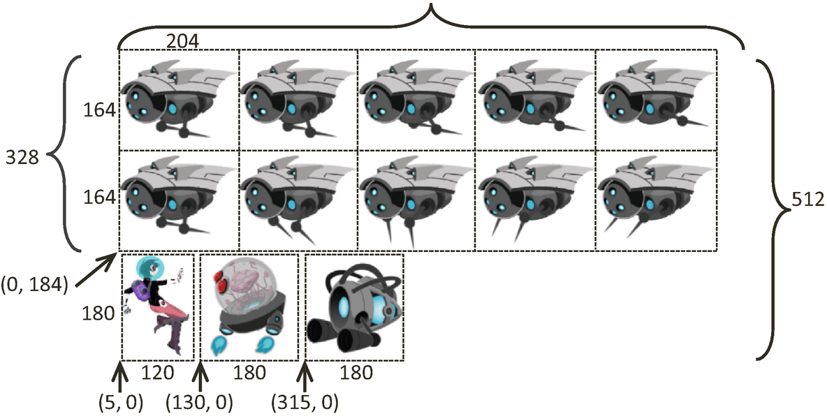
Example sprite sheet: minion_sprite.png composed of lower-resolution images of different objects
Sprite sheets are defined to optimize both memory and processing requirements. For example, recall that WebGL only supports textures that are defined by images with 2x × 2y resolutions. This requirement means that the Dye character at a resolution of 120x180 must be stored in a 128x256 (27 × 28) image in order for it to be created as a WebGL texture. Additionally, if the 13 elements of Figure 5-7 were stored as separate image files, then it would mean 13 slow file system accesses would be required to load all the images, instead of one single system access to load the sprite sheet.
Pixel positions: The lower-left corner is (315, 0), and the upper-right corner is (495, 180).
UV values: The lower-left corner is (0.308, 0.0), and the upper-right corner is (0.483, 0.352).
Use in Model Space : Texture mapping of the element is accomplished by associating the corresponding uv values with the xy values at each vertex position.
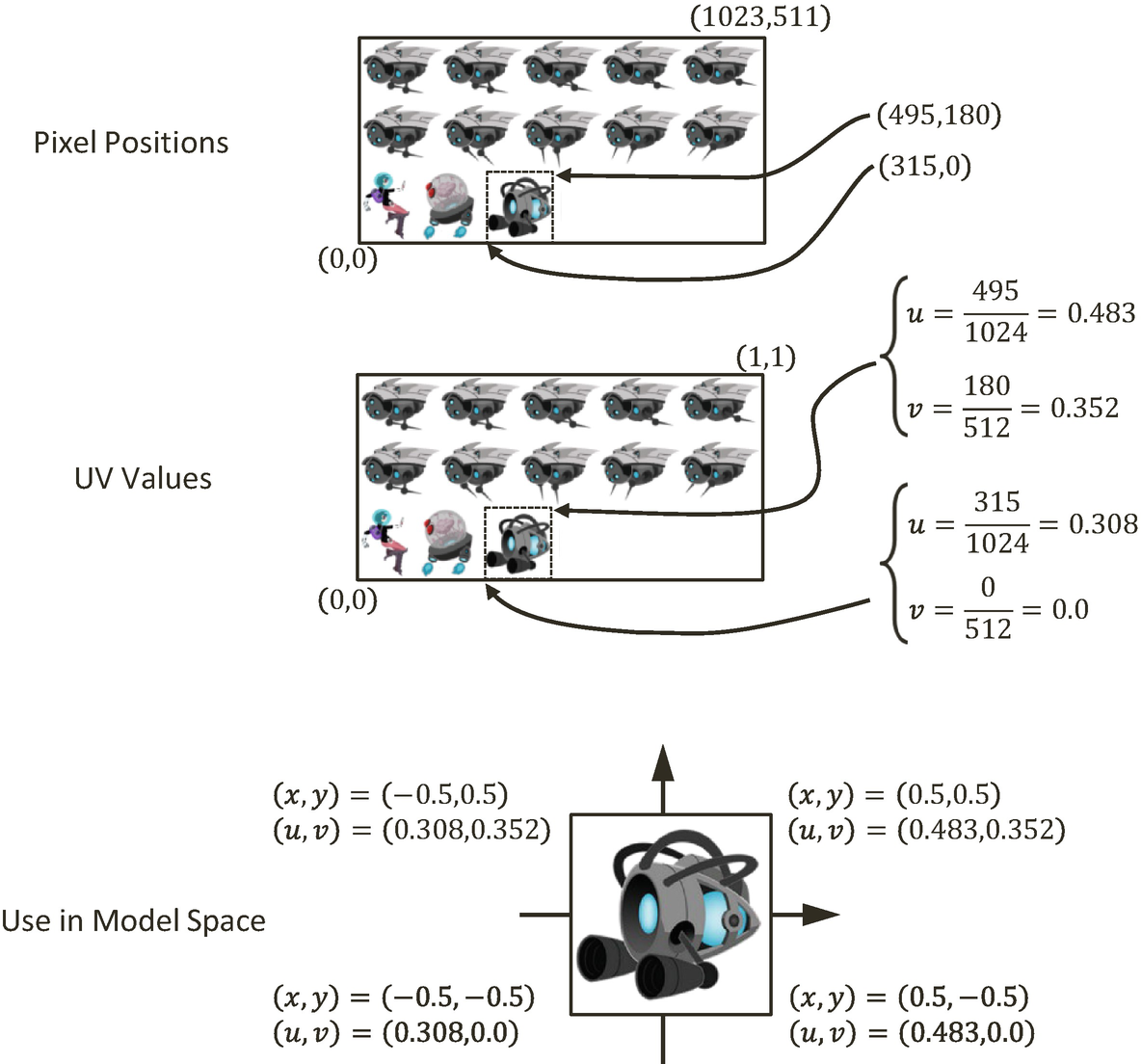
A conversion of coordinate from pixel position to uv values and used for mapping on geometry
The Sprite Shaders Project
Running the Sprite Shaders project
Right-arrow key: Moves the Dye character (the hero) right and loops to the left boundary when the right boundary is reached
Left-arrow key: Moves the hero left and resets the position to the middle of the window when the left boundary is reached
To gain a deeper understanding of texture coordinates
To experience defining subregions within an image for texture mapping
To draw squares by mapping from sprite sheet elements
To prepare for working with sprite animation and bitmap fonts
You can find the following external resource files in the assets folder: consolas-72.png and minion_sprite.png . Notice that minion_sprite.png is the image shown in Figure 5-7.
Defining a texture coordinate buffer in the SpriteShader
Interface GLSL Texture Shaders to the Engine with SpriteShader
- 1.
Create a new file in the src/engine/shaders folder and name it sprite_shader.js.
- 2.
Define the SpriteShader class and its constructor to extend the TextureShader class:
- 3.
Define a function to set the WebGL texture coordinate buffer:
- 4.
Override the texture coordinate accessing function, _getTexCoordBuffer(), such that when the shader is activated, the locally allocated dynamic buffer is returned and not the global static buffer. Note that the activate() function is inherited from TextureShader.
- 5.
Remember to export the class:
SpriteRenderable Class
- 1.
Create a new file in the src/engine/renderables folder and name it sprite_renderable.js.
- 2.
Define the SpriteRenderable class and constructor to extend from the TextureRenderable class. Notice that the four instance variables, mElmLeft, mElmRight, mElmTop, and mElmBottom, together identify a subregion within the Texture Space. These are the bounds of a sprite sheet element.
- 3.
Define an enumerated data type with values that identify corresponding offset positions of a WebGL texture coordinate specification array:
An enumerated data type has a name that begins with an “e”, as in eTexCoordArrayIndex.
- 4.
Define functions to allow the specification of uv values for a sprite sheet element in both texture coordinate space (normalized between 0 and 1) and with pixel positions (which are converted to uv values):
- 5.
Add a function to construct the texture coordinate specification array that is appropriate for passing to the WebGL context:
- 6.
Override the draw() function to load the specific texture coordinate values to WebGL context before the actual drawing:
- 7.
Finally, remember to export the class and the defined enumerated type:
Facilitate Sharing with shader_resources
- 1.
In the engine/core/shader_resources.js file, import SpriteShader, add a variable for storing, and define the corresponding getter function to access the shared SpriteShader instance:
- 2.
Modify the createShaders() function to create the SpriteShader:
- 3.
Update the cleanUp() function for proper release of resources:
- 4.
Make sure to export the new functionality:
Export New Functionality to the Client
Testing the SpriteRenderable
- 1.
The constructing, loading, unloading, and drawing of MyGame are similar to previous examples, so the details will not be repeated here. Please refer to the source code in the src/my_game folder for details.
- 2.
Modify the init() function as follows.
- a.
After the camera is set up in step A, notice that in step B both mPortal and mCollector are created based on the same image, kMinionSprite , with the respective setElementPixelPositions() and setElementUVCoordinate() calls to specify the actual sprite element to use for rendering.
- b.
Step C creates two additional SpriteRenderable objects: mFontImage and mMinion. The sprite element uv coordinate settings are the defaults where the texture image will cover the entire geometry.
- c.
Similar to step B, step D creates the hero character as a SpriteRenderable object based on the same kMinionSprite image. The sprite sheet element that corresponds to the hero is identified with the setElementPixelPositions() call.
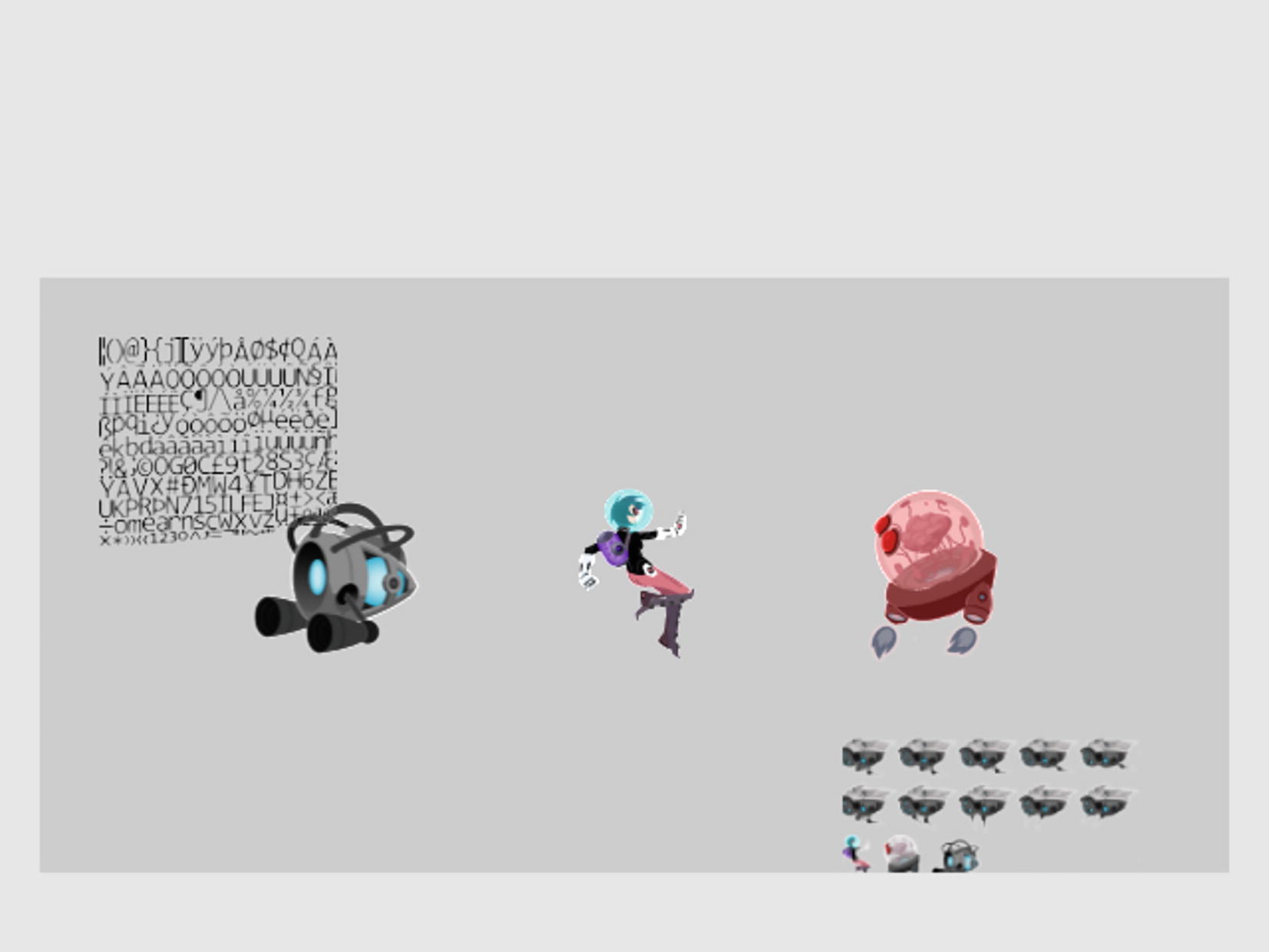
Notice that in this example, four of the five SpriteRenderable objects created are based on the same kMinionSprite image.
- 3.
The update() function is modified to support the controlling of the hero object and changes to the uv values.
- a.
Observe that the keyboard control and the drawing of the hero object are identical to previous projects.
- b.
Notice the calls to setElementUVCoordinate() for mFontImage and mMinion. These calls continuously decrease and reset the V values that correspond to the bottom, the U values that correspond to the right for mFontImage, the V values that correspond to the top, and the U values that correspond to the left for mMinion. The end results are the continuous changing of texture and the appearance of a zooming animation on these two objects
Sprite Animations
In games, you often want to create animations that reflect the movements or actions of your characters. In the previous chapter, you learned about moving the geometries of these objects with transformation operators. However, as you have observed when controlling the hero character in the previous example, if the textures on these objects do not change in ways that correspond to the control, the interaction conveys the sensation of moving a static image rather than setting a character in motion. What is needed is the ability to create the illusion of animations on geometries when desired.
In the previous example, you observed from the mFontImage and mMinion objects that the appearance of an animation can be created by constantly changing the uv values on a texture-mapped geometry. As discussed at the beginning of this chapter, one way to control this type of animation is by working with an animated sprite sheet.
Overview of Animated Sprite Sheets
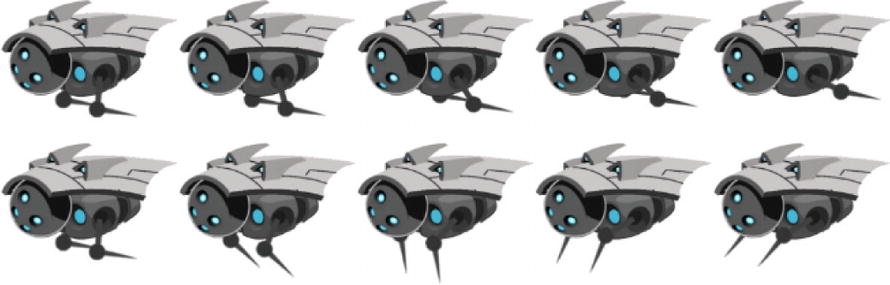
An animated sprite sheet organized into two rows representing two animated sequences of the same object
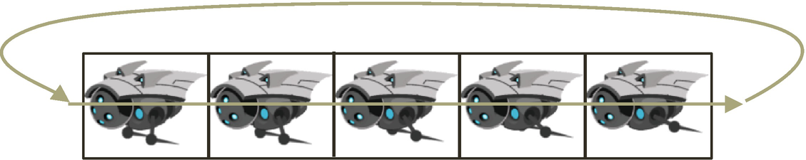
A sprite animation sequence that loops
The Sprite Animation Project
Running the Sprite Animate Shaders project
Right-arrow key: Moves the hero right; when crossing the right boundary, the hero is wrapped back to the left boundary
Left-arrow key: Opposite movements of the right arrow key
Number 1 key: Animates by showing sprite elements continuously from right to left
Number 2 key: Animates by showing sprite elements moving back and forth continuously from left to right and right to left
Number 3 key: Animates by showing sprite elements continuously from left to right
Number 4 key: Increases the animation speed
Number 5 key: Decreases the animation speed
To understand animated sprite sheets
To experience the creation of sprite animations
To define abstractions for implementing sprite animations
You can find the same files as in the previous project in the assets folder.
SpriteAnimateRenderable Class
Sprite animation can be implemented by strategically controlling the uv values of a SpriteRenderable to display the appropriate sprite element at desired time periods. For this reason, only a single class, SpriteAnimateRenderable , needs to be defined to support sprite animations.
- 1.
Create a new file in the src/engine/renderables folder and name it sprite_animate_renderable.js.
- 2.
Define an enumerated data type for the three different sequences to animate:
The eAnimationType enum defines three modes for animation:
- a.
eRight starts at the leftmost element and animates by iterating toward the right along the same row. When the last element is reached, the animation continues by starting from the leftmost element again.
- b.
eLeft is the reverse of eRight; it starts from the right, animates toward the left, and continues by starting from the rightmost element after reaching the leftmost element.
- c.
eSwing is a continuous loop from left to right and then from right to left.
- 3.
Define the SpriteAnimateRenderable class to extend from SpriteRenderable and define the constructor:
- a.
The first set, including mFirstElmLeft, mElmTop, and so on, defines the location and dimensions of each sprite element and the number of elements in the animation. This information can be used to accurately compute the texture coordinate for each sprite element when the elements are ordered by rows and columns. Note that all coordinates are in texture coordinate space (0 to 1).
- b.
The second set stores information on how to animate, the mAnimationType of left, right, or swing, and how much time, mUpdateInterval, to wait before advancing to the next sprite element. This information can be changed during runtime to reverse, loop, or control the speed of a character’s movement.
- c.
The third set, mCurrentAnimAdvance and mCurrentElm, describes offset for advancing and the current frame number. Both of these variables are in units of element counts and are not designed to be accessed by the game programmer because they are used internally to compute the next sprite element for display.
- 4.
Define the _initAnimation() function to compute the proper vales for mCurrentAnimAdance and mCurrentElm according to the current animation type:
- 5.
Define the _setSpriteElement() function to compute and load the uv values of the currently identified sprite element for rendering:
- 6.
Define a function to set the animation type. Note that the animation is always reset to start from the beginning when the animation type (left, right, or swing) is changed.
- 7.
Define a function for specifying a sprite animation sequence. The inputs to the function are in pixels and are converted to texture coordinates by dividing by the width and height of the image.
- 8.
Define functions to change animation speed, either directly or by an offset:
- 9.
Define a function to advance the animation for each game loop update:
- 10.
Finally, remember to export the defined class and enumerated animation type:
Export New Functionality to the Client
Testing Sprite Animation
- 1.
The constructing, loading, unloading, and drawing of MyGame are similar to the previous example and the details are not repeated.
- 2.
In the init() function , add code to create and initialize the SpriteAnimateRenderable objects between steps C and D:
- 3.
The update() function must invoke the SpriteAnimateRenderable object’s updateAnimation() function to advance the sprite animation:
The keys 1, 2, and 3 change the animation type, and keys 4 and 5 change the animation speed. Note that the limit of the animation speed is the update rate of the game loop.
Fonts and Drawing of Text
A valuable tool that many games use for a variety of tasks is text output. Drawing of text messages is an efficient way to communicate to the user as well as you, the developer. For example, text messages can be used to communicate the game’s story, the player’s score, or debugging information during development. Unfortunately, WebGL does not support the drawing of text. This section briefly introduces bitmap fonts and introduces FontRenderable objects to support the drawing of texts.
Bitmap Fonts

An example bitmap font sprite image

A snippet of the XML file with the decoding information for the bitmap font image shown in Figure 5-14
Notice that the decoding information as shown in Figure 5-15 uniquely defines the uv coordinate positions for each character in the image, as shown in Figure 5-14. In this way, displaying individual characters from a bitmap font sprite image can be performed in a straightforward manner by the SpriteRenderable objects .
There are many bitmap font file formats. The format used in this book is the AngleCode BMFont–compatible font in XML form. BMFont is an open source software that converts vector fonts, such as TrueType and OpenType, into bitmap fonts. See www.angelcode.com/products/bmfont/ for more information.
The Font Support Project
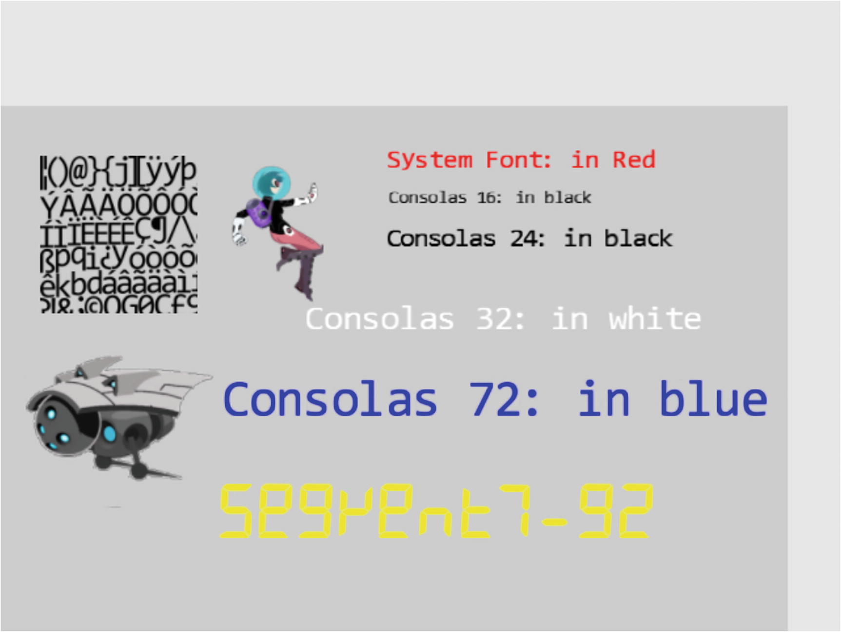
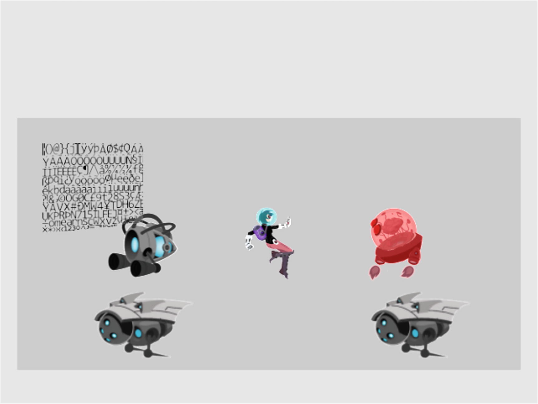
Running the Font Support project
Number keys 0, 1, 2, and 3: Select the Consolas, 16, 24, 32, or 72 fonts, respectively, for size modification.
Up/down key while holding down X/Y key: Increases or decreases (arrow keys) the width (X key) or the height (Y key) of the selected font.
Left- and right-arrow keys: Move the hero left or right. The hero wraps if it exits the bounds.
To understand bitmap fonts
To gain a basic understanding of drawing text strings in a game
To implement text drawing support in your game engine
You can find the following external resource files in the assets folder: consolas-72.png and minion_sprite.png. In the assets/fonts folder are the bitmap font sprite image files and the associated XML files that contain the decoding information: consolas-16.fnt, consolas-16.png, consolas-24.fnt, consolas-24.png, consolas-32.fnt, consolas-32.png, consolas-72.fnt, consolas-72.png, segment7-96.fnt, segment7-96.png, system-default-font.fnt, and system-default-font.png.
Notice that the .fnt and .png files are paired. The former contains decoding information for the latter. These file pairs must be included in the same folder for the engine to load the font properly. system-default-font is the default font for the game engine, and it is assumed that this font is always present in the asset/fonts folder.
The actions of parsing, decoding, and extracting of character information from the .fnt files are independent from the foundational operations of a game engine. For this reason, the details of these operations are not presented. If you are interested, you should consult the source code.
Loading and Storing Fonts in the Engine
- 1.
Create a new file in the src/engine/resources folder and name it font.js.
- 2.
Import the resource management functionality from the xml module for loading the .fnt file and the texture module for the .png sprite image file, and define local constants for these file extensions:
- 3.
Define a class for storing uv coordinate locations and the size associated with a character. This information can be computed based on the contents from the .fnt file.
- 4.
Define two functions to return proper extensions based on a path with no file extension. Note that fontName is a path to the font files but without any file extensions. For example, assets/fonts/system-default-font is the string and the two functions identify the two associated .fnt and .png files.
- 5.
Define the load() and unload() functions. Notice that two file operations are actually invoked in each: one for the .fnt and the second for the .png files.
- 6.
Define a function to inquire the loading status of a given font:
- 7.
Define a function to compute CharacterInfo based on the information presented in the .fnt file:
Details of decoding and extracting information for a given character are omitted because they are unrelated to the rest of the game engine implementation.
For details of the .fnt format information, please refer to www.angelcode.com/products/bmfont/doc/file_format.html.
- 8.
Finally, remember to export the functions from this module:
Adding a Default Font to the Engine
- 1.
Create a file in the src/engine/resources folder and name it default_resources.js, import functionality from the font and resource_map modules, and define a constant string and its getter function for the path to the default system font:
- 2.
Define an init() function to issue the default system font loading request in a JavaScript Promise and append the Promise to the array of outstanding load requests in the resource_map. Recall that the loop.start() function in the loop module waits for the fulfillment of all resource_map loading promises before starting the game loop. For this reason, as in the case of all other asynchronously loaded resources, by the time the game loop begins, the default system font will have been properly loaded.
- 3.
Define the cleanUp() function to release all allocated resources, in this case, unload the font:
- 4.
Lastly, remember to export all defined functionality:
Defining a FontRenderable Object to Draw Texts
- 1.
Create a new file in the src/engine/renderables folder and name it font_renderable.js.
- 2.
Define the FontRenderable class and its constructor to accept a string as its parameter:
- a.
The aString variable is the message to be drawn.
- b.
Notice that FontRenderable objects do not customize the behaviors of SpriteRenderable objects. Rather, it relies on a SpriteRenderable object to draw each character in the string. For this reason, FontRenderable is not a subclass of but instead contains an instance of the SpriteRenderable object, the mOneChar variable.
- 3.
Define the draw() function to parse and draw each character in the string using the mOneChar variable :
The dimension of each character is defined by widthOfOneChar and heightOfOneChar where the width is simply dividing the total FontRenderable width by the number of characters in the string. The for loop then performs the following operations:
- a.
Extracts each character in the string
- b.
Calls the getCharInfo() function to receive the character’s uv values and size information in charInfo
- c.
Uses the uv values from charInfo to identify the sprite element location for mOneChar (by calling and passing the information to the mOneChar.setElementUVCoordinate() function )
- d.
Uses the size information from charInfo to compute the actual size (xSize and ySize) and location offset for the character (xOffset and yOffset) and draws the character mOneChar with the appropriate settings
- 4.
Implement the getters and setters for the transform, the text message to be drawn, the font to use for drawing, and the color:
- 5.
Define the setTextHeight() function to define the height of the message to be output:
- 6.
Finally, remember to export the defined class:
FontRenderable does not support the rotation of the entire message. Text messages are always drawn horizontally from left to right.
Initialize, Cleaning, and Export Font Functionality
- 1.
Edit index.js to import functionality from the font and default_resources modules and the FontRenderable class:
- 2.
Add default resources initialization and cleanup in the engine init() and cleanUp() functions:
- 3.
Remember to export the newly defined functionality:
Testing Fonts
- 4.
In the my_game.js file, modify the constructor to define corresponding variables for printing the messages, and modify the draw() function to draw all objects accordingly. Please refer to the src/my_game/my_game.js file for the details of the code.
- 5.
Modify the load() function to load the textures and fonts. Once again, notice that the font paths, for example, assets/fonts/consolas-16, do not include file name extensions. Recall that this path will be appended with .fnt and .png, where two separate files will be loaded to support the drawing of fonts.
- 6.
Modify the unload() function to unload the textures and fonts:
- 7.
Define a private _initText() function to set the color, location, and height of a FontRenderable object. Modify the init() function to set up the proper WC system and initialize the fonts. Notice the calls to setFont() function to change the font type for each message.
- 8.
Modify the update() function with the following:
- a.
Select which FontRenderable object to work with based on keyboard 0 to 4 input.
- b.
Control the width and height of the selected FontRenderable object when both the left/right arrow and X/Y keys are pressed.
You can now interact with the Font Support project to modify the size of each of the displayed font message and to move the hero toward the left and right.
Summary
In this chapter, you learned how to paste, or texture map, images on unit squares to better represent objects in your games. You also learned how to identify a selected subregion of an image and texture map to the unit square based on the normalize-ranged Texture Coordinate System. The chapter then explained how sprite sheets can reduce the time required for loading texture images while facilitating the creation of animations. This knowledge was then generalized and applied to the drawing of bitmap fonts.
The implementation of texture mapping and sprite sheet rendering takes advantage of an important aspect of game engine architecture: the SimpleShader/Renderable object pair where JavaScript SimpleShader objects are defined to interface with corresponding GLSL shaders and Renderable objects to facilitate the creation and interaction with multiple object instances. For example, you created TextureShader to interface with TextureVS and TextureFS GLSL shaders and created TextureRenderable for the game programmers to work with. This same pattern is repeated for SpriteShader and SpriteRenderable. The experience from SpriteShader objects paired with SpriteAnimateRenderable shows that, when appropriate, the same shader object can support multiple renderable object types in the game engine. This SimpleShader/Renderable pair implementation pattern will appear again in Chapter 8, when you learn to create 3D illumination effects.
At the beginning of this chapter, your game engine supports the player manipulating objects with the keyboard and the drawing of these objects in various sizes and orientations. With the functionality from this chapter, you can now represent these objects with interesting images and create animations of these objects when desired. In the next chapter, you will learn about defining and supporting behaviors for these objects including pseudo autonomous behaviors such as chasing and collision detections.
Game Design Considerations
In Chapter 4, you learned how responsive game feedback is essential for making players feel connected to a game world and that this sense of connection is known as presence in game design. As you move through future chapters in this book, you’ll notice that most game design is ultimately focused on enhancing the sense of presence in one way or another, and you’ll discover that visual design is one of the most important contributors to presence. Imagine, for example, a game where an object controlled by the player (also known as the hero object) must maneuver through a 2D platformer-style game world; the player’s goal might be to use the mouse and keyboard to jump the hero between individual surfaces rendered in the game without falling through gaps that exist between those surfaces. The visual representation of the hero and other objects in the environment determines how the player identifies with the game setting, which in turn determines how effectively the game creates presence: Is the hero represented as a living creature or just an abstract shape like a square or circle? Are the surfaces represented as building rooftops, as floating rocks on an alien planet, or simply as abstract rectangles? There is no right or wrong answer when it comes to selecting a visual representation or game setting, but it is important to design a visual style for all game elements that feels unified and integrated into whatever game setting you choose (e.g., abstract rectangle platforms may negatively impact presence if your game setting is a tropical rainforest).
The Texture Shaders project demonstrated how .png images with transparency, more effectively integrate game elements into the game environment than formats like .jpg that don’t support transparency. If you move the hero (represented here as simply a rectangle) to the right, nothing on the screen changes, but if you move the hero to the left, you’ll eventually trigger a state change that alters the displayed visual elements as you did in the Scene Objects project from Chapter 4. Notice how much more effectively the robot sprites are integrated into the game scene when they’re .png files with transparency on the gray background compared to when they’re .jpg images without transparency on the blue background.
The Sprite Shaders project introduces a hero that more closely matches other elements in the game setting: you’ve replaced the rectangle from the Texture Shaders project with a humanoid figure stylistically matched to the flying robots on the screen, and the area of the rectangular hero image not occupied by the humanoid figure is transparent. If you were to combine the hero from the Sprite Shaders project with the screen-altering action in the Texture Shaders project, imagine that as the hero moves toward the robot on the right side of the screen, the robot might turn red when the hero gets too close. The coded events are still simple at this point, but you can see how the visual design and a few simple triggered actions can already begin to convey a game setting and enhance presence.
Note that as game designers we often become enamored with highly detailed and elaborate visual designs, and we begin to believe that higher fidelity and more elaborate visual elements are required to make the best games; this drive for ever-more powerful graphics is the familiar race that many AAA games engage in with their competition. While it’s true that game experiences and the sense of presence can be considerably enhanced when paired with excellent art direction, excellence does not always require elaborate and complex. Great art direction relies on developing a unified visual language where all elements harmonize with each other and contribute to driving the game forward and that harmony can be achieved with anything from simple shapes and colors in a 2D plane to hyperreal 3D environments and every combination in between.
Adding animated motion to the game’s visual elements can further enhance game presence because animation brings a sense of cinematic dynamism to gameplay that further connects players to the game world. We typically experience motion in our world as interconnected systems; when you walk across the room, for example, you don’t just glide without moving your body but move different parts of your body together in different ways. By adding targeted animations to objects onscreen that cause those objects to behave in ways you might expect complex systems to move or act, you connect players in a more immersive and convincing way to what’s going on in the game world. The Sprite Animation project demonstrates how animation increases presence by allowing you to articulate the flying robot’s spikes, controlling direction and speed. Imagine again combining the Sprite Animation project with the earlier projects in this chapter; as the hero moves closer to the robot, it might first turn red, eventually triggering the robot’s animations and moving it either toward or away from the player. Animations often come fairly late in the game design process because it’s usually necessary to first have the game mechanic and other systems well defined to avoid time-consuming changes that may be required as environments and level designs are updated. Designers typically use simple placeholder assets in the early stages of development, adding polished and animated final assets only when all of the other elements of gameplay have been finalized to minimize the need for rework.
As was the case with visual design, the animation approach need not be complex to be effective. While animation needs to be intentional and unified and should feel smooth and stutter-free unless it’s intentionally designed to be otherwise, a wide degree of artistic license can be employed in how movement is represented onscreen.
The Font Support project introduced you to game fonts. While fonts rarely have a direct impact on gameplay, they can have a dramatic impact on presence. Fonts are a form of visual communication, and the style of the font is often as important as the words it conveys in setting tone and mood and can either support or detract from the game setting and visual style. Pay particular attention to the fonts displayed in this project, and note how the yellow font conveys a digital feeling that’s matched to the science fiction–inspired visual style of the hero and robots, while the Consolas font family with its round letterforms feels a bit out of place with this game setting (sparse though the game setting may still be). As a more extreme example, imagine how disconnected a flowing calligraphic script font (the type typically used in high-fantasy games) would appear in a futuristic game that takes place on a spaceship.
There are as many visual style possibilities for games as there are people and ideas, and great games can feature extremely simple graphics. Remember that excellent game design is a combination of the nine contributing elements (return to the introduction if you need to refresh your memory), and the most important thing to keep in mind as a game designer is maintaining focus on how each of those elements harmonizes with and elevates the others to create something greater than the sum of its parts.