Implement operations that are commonly employed in manipulating a camera
Interpolate values between old and new to create a smooth transition
Understand how some motions or behaviors can be described by simple mathematical formulations
Build games with multiple camera views
Transform positions from the mouse-clicked pixel to the World Coordinate (WC) position
Program with mouse input in a game environment with multiple cameras
Introduction
Your game engine is now capable of representing and drawing objects. With the basic abstraction mechanism introduced in the previous chapter, the engine can also support the interactions and behaviors of these objects. This chapter refocuses the attention on controlling and interacting with the Camera object that abstracts and facilitates the presentation of the game objects on the canvas. In this way, your game engine will be able to control and manipulate the presentation of visually appealing game objects with well-structured behaviors.
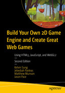
Review of WC parameters that define a Camera object
In this book, the WC window or WC bounds are used to refer to the WC window bounds.
The Camera object abstraction allows the game programmer to ignore the details of WC bounds and the HTML canvas and focus on designing a fun and entertaining gameplay experience. Programming with a Camera object in a game level should reflect the use of a physical video camera in the real world. For example, you may want to pan the camera to show your audiences the environment, you may want to attach the camera on an actress and share her journey with your audience, or you may want to play the role of a director and instruct the actors in your scene to stay within the visual ranges of the camera. The distinct characteristics of these examples, such as panning or following a character’s view, are the high-level functional specifications. Notice that in the real world you do not specify coordinate positions or bounds of windows.
This chapter introduces some of the most commonly encountered camera manipulation operations including clamping, panning, and zooming. Solutions in the form of interpolation will be derived to alleviate annoying or confusing abrupt transitions resulting from the manipulation of cameras. You will also learn about supporting multiple camera views in the same game level and working with mouse input.
Camera Manipulations
In a 2D world, you may want to clamp or restrict the movements of objects to be within the bounds of a camera, to pan or move the camera, or to zoom the camera into or away from specific areas. These high-level functional specifications can be realized by strategically changing the parameters of the Camera object: the WC center and the Wwc × Hwc of the WC window. The key is to create convenient functions for the game developers to manipulate these values in the context of the game. For example, instead of increasing/decreasing the width/height of the WC windows, zoom functions can be defined for the programmer.
The Camera Manipulations Project
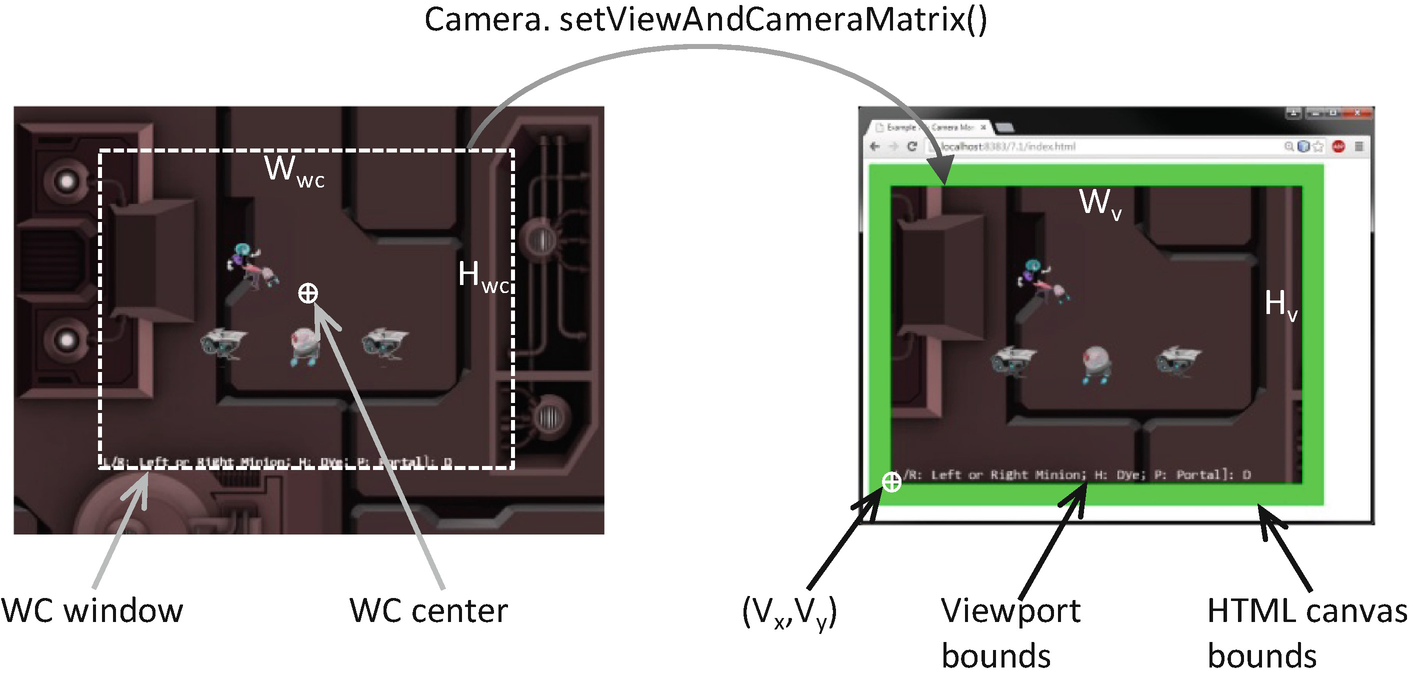
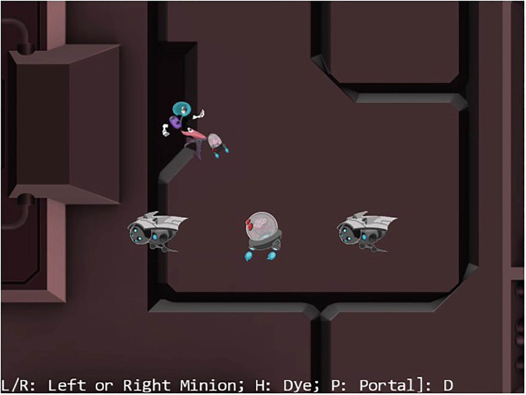
Running the Camera Manipulations project
WASD keys: Move the Dye character (the Hero object). Notice that the camera WC window updates to follow the Hero object when it attempts to move beyond 90 percent of the WC bounds.
Arrow keys: Move the Portal object. Notice that the Portal object cannot move beyond 80 percent of the WC bounds.
L/R/P/H keys: Select the Left minion, Right minion, Portal object, or Hero object to be the object in focus; the L/R keys also set the camera to center on the Left or Right minion.
N/M keys: Zoom into or away from the center of the camera.
J/K keys: Zoom into or away while ensuring the constant relative position of the currently in-focus object. In other words, as the camera zooms, the positions of all objects will change except that of the in-focus object.
To experience some of the common camera manipulation operations
To understand the mapping from manipulation operations to the corresponding camera parameter values that must be altered
To implement camera manipulation operations
You can find the following external resources in the assets folder: the fonts folder that contains the default system fonts and three texture images (minion_portal.png, minion_sprite.png, and bg.png). The Portal object is represented by the first texture image, the remaining objects are sprite elements of minion_sprite.png, and the background is a large TextureRenderable object texture mapped with bg.png.
Organize the Source Code
camera_main.js for implementing the basic functionality from previous projects
camera_manipulation.js for supporting the newly introduced manipulation operations
camera.js for serving as the class access point
- 1.
Create a new folder called cameras in src/engine. Move the camera.js file into this folder and rename it to camera_main.js.
- 2.
Create a new file in src/engine/cameras and name it camera_manipulation.js. This file will be used to extend the Camera class functionality in supporting manipulations. Add in the following code to import and export the basic Camera class functionality. For now, this file does not contain any useful source code and thus does not serve any purpose. You will define the appropriate extension functions in the following subsection.
- 3.
Create a new camera.js to serve as the Camera access point by adding the following code:
With this structure of the source code files, camera_main.js implements all the basic functionality and exports to camera_manipulation.js that defines additional functionality for the Camera class. Finally, camera.js imports the extended functions from camera_manipulation.js. The users of the Camera class can simply import from camera.js and will have access to all of the defined functionality. This allows camera.js to serve as the access point to the Camera class while hiding the details of the implementation source code structure.
Support Clamping to Camera WC Bounds
The aXform object can be the Transform of a GameObject or Renderable object. The clampAtBoundary() function ensures that the bounds of the aXform remain inside the WC bounds of the camera by clamping the aXform position. The zone variable defines a percentage of clamping for the WC bounds. For example, a 1.0 would mean clamping to the exact WC bounds, while a 0.9 means clamping to a bound that is 90 percent of the current WC window size. It is important to note that the clampAtBoundary() function operates only on bounds that collide with the camera WC bounds. For example, if the aXform object has its bounds that are completely outside of the camera WC bounds, it will remain outside.
Define Camera Manipulation Operations in camera_manipulation.js File
- 1.
Edit camera_manipulate.js. Ensure you are adding code between the initial import and final export of the Camera class functionality.
- 2.
Import the bounding box collision status, and define the panWidth() function to pan the camera based on the bounds of a Transform object. This function is complementary to the clampAtBoundary() function, where instead of changing the aXform position, the camera is moved to ensure the proper inclusion of the aXform bounds. As in the case of the clampAtBoundary() function, the camera will not be changed if the aXform bounds are completely outside the tested WC bounds area.
- 3.
Define camera panning functions panBy() and panTo() by appending to the Camera class prototype. These two functions change the camera WC center by adding a delta to it or moving it to a new location.
- 4.
Define functions to zoom the camera with respect to the center or a target position:
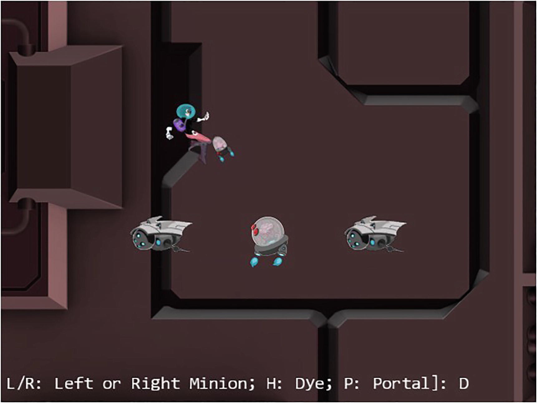
Zooming toward the WC Center and toward a target position
Manipulating the Camera in MyGame
In the listed code, the first four if statements select the in-focus object, where L and R keys also re-center the camera by calling the panTo() function with the appropriate WC positions. The second set of four if statements control the zoom, either toward the WC center or toward the current in-focus object. Then the function clamps the Brain and Portal objects to within 90 percent and 80 percent of the WC bounds, respectively. The function finally ends by panning the camera based on the transform (or position) of the Hero object.
You can now run the project and move the Hero object with the WASD keys. Move the Hero object toward the WC bounds to observe the camera being pushed. Continue pushing the camera with the Hero object; notice that because of the clampAtBoundary() function call, the Portal object will in turn be pushed such that it never leaves the camera WC bounds. Now press the L/R key to observe the camera center switching to the center on the Left or Right minion. The N/M keys demonstrate straightforward zooming with respect to the center. To experience zooming with respect to a target, move the Hero object toward the top left of the canvas and then press the H key to select it as the zoom focus. Now, with your mouse pointer pointing at the head of the Hero object, you can press the K key to zoom out first and then the J key to zoom back in. Notice that as you zoom, all objects in the scene change positions except the areas around the Hero object. Zooming into a desired region of a world is a useful feature for game developers with many applications. You can experience moving the Hero object around while zooming into/away from it.
Interpolation
It is now possible to manipulate the camera based on high-level functions such as pan or zoom. However, the results are often sudden or visually incoherent changes to the rendered image, which may result in annoyance or confusion. For example, in the previous project, the L or R key causes the camera to re-center with a simple assignment of new WC center values. The abrupt change in camera position results in the sudden appearance of a seemingly new game world. This is not only visually distracting but can also confuse the player as to what has happened.
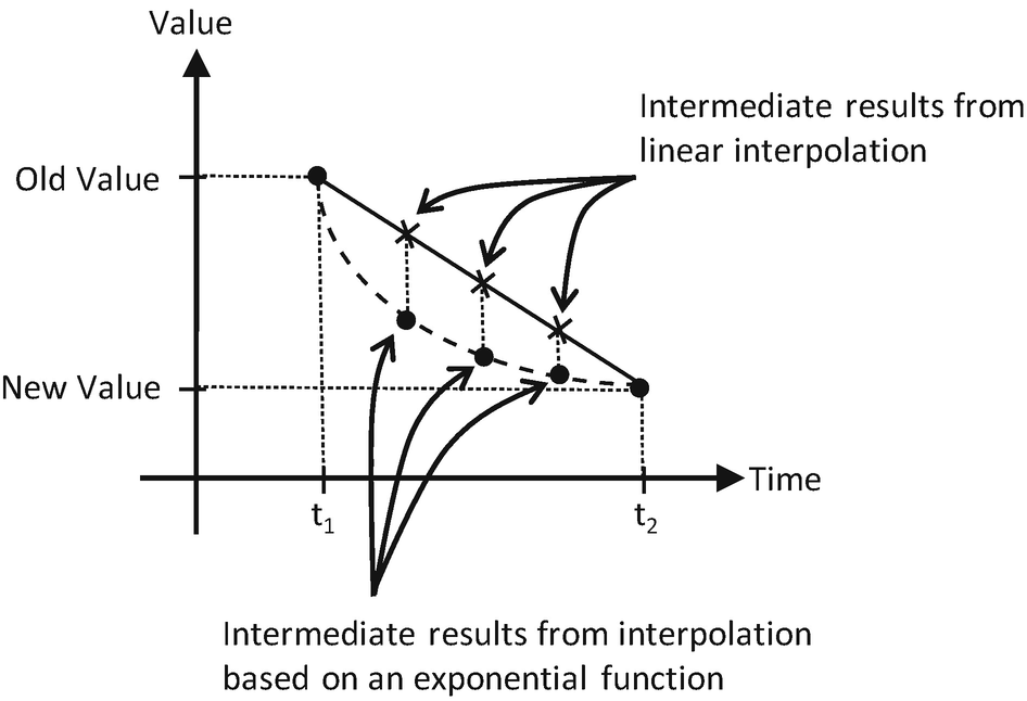
Interpolating values based on linear and exponential functions
Figure 7-4 shows that there are multiple ways to interpolate values over time. For example, linear interpolation computes intermediate results according to the slope of the line connecting the old and new values. In contrast, an exponential function may compute intermediate results based on percentages from previous values. In this way, with linear interpolation, a camera position would move from an old to new position with a constant speed similar to a moving (or panning) a camera at some constant speed. In comparison, the interpolation based on the given exponential function would move the camera position rapidly at first and then slow down quickly over time giving a sensation of moving and focusing the camera on a new target.
Human motions and movements typically follow the exponential interpolation function. For example, try turning your head from facing the front to facing the right or moving your hand to pick up an object on your desk. Notice that in both cases, you began with a relatively quick motion and slowed down significantly when the destination is in close proximity. That is, you probably started by turning your head quickly and slowed down rapidly as your view approaches your right side, and it is likely your hand started moving quickly toward the object and slowed down significantly when the hand is almost reaching the object. In both of these examples, your displacements followed the exponential interpolation function as depicted in Figure 7-4, quick changes followed by a rapid slow down as the destination approaches. This is the function you will implement in the game engine because it mimics human movements and is likely to seem natural to human players.
Linear interpolation is often referred to as LERP or lerp. The result of lerp is the linear combination of an initial and a final value. In this chapter, and in almost all cases, the exponential interpolation depicted in Figure 7-4 is approximated by repeatedly applying the lerp function where in each invocation, the initial value is the result of the previous lerp invocation. In this way, the exponential function is approximated with a piecewise linear function.
This section introduces the Lerp and LerpVec2 utility classes to support smooth and gradual camera movements resulting from camera manipulation operations.
The Camera Interpolations Project
Running the Camera Interpolations project
WASD keys: Move the Dye character (the Hero object). Notice that the camera WC window updates to follow the Hero object when it attempts to move beyond 90 percent of the WC bounds.
Arrow keys: Move the Portal object. Notice that the Portal object cannot move beyond 80 percent of the WC bounds.
L/R/P/H keys: Select the Left minion, Right minion, Portal object, or Hero object to be the object in focus. The L/R keys also set the camera to focus on the Left or Right minion.
N/M keys: Zoom into or away from the center of the camera.
J/K keys: Zoom into or away while ensuring constant relative position of the currently in-focus object. In other words, as the camera zooms, the positions of all objects will change except that of the in-focus object.
To understand the concept of interpolation between given values
To implement interpolation supporting gradual camera parameter changes
To experience interpolated changes in camera parameters
As in previous projects, you can find external resource files in the assets folder.
Interpolation as a Utility
Similar to the Transform class supporting transformation functionality and the BoundingBox class supporting collision detection, a Lerp class can be defined to support interpolation of values. To keep the source code organized, a new folder should be defined to store these utilities.
Create the src/engine/utils folder and move the transform.js and bounding_box.js files into this folder.
The Lerp Class
- 1.
Create a new file in the src/engine/utils folder, name it lerp.js, and define the constructor. This class is designed to interpolate values from mCurrentValue to mFinalValue in the duration of mCycles. During each update, intermediate results are computed based on the mRate increment on the difference between mCurrentValue and mFinalValue, as shown next.
- 2.
Define the function that computes the intermediate results:
- 3.
Define a function to configure the interpolation. The mRate variable defines how quickly the interpolated result approaches the final value. A mRate of 0.0 will result in no change at all, where 1.0 causes instantaneous change. The mCycle variable defines the duration of the interpolation process .
- 4.
Define relevant getter and setter functions. Note that the setFinal() function both sets the final value and triggers a new round of interpolation computation.
- 5.
Define the function to trigger the computation of each intermediate result:
- 6.
Finally, make sure to export the defined class:
The LerpVec2 Class
- 1.
Create a new file in the src/engine/utils folder, name it lerp_vec2.js, and define its constructor:
- 2.
Override the _interpolateValue() function to compute intermediate results for vec2:
The vec2.lerp() function defined in the gl-matrix.js file computes the vec2 components for x and y. The computation involved is identical to the _interpolateValue() function in the Lerp class.
Lastly, remember to update the engine access file, index.js, to forward the newly defined Lerp and LerpVec2 functionality to the client.
Represent Interpolated Intermediate Results with CameraState
- 1.
Create a new file in the src/engine/cameras folder, name it camera_state.js, import the defined Lerp functionality, and define the constructor:
- 2.
Define the getter and setter functions:
- 3.
Define the update function to trigger the interpolation computation:
- 4.
Define a function to configure the interpolation :
The stiffness variable is the mRate of Lerp. It defines how quickly the interpolated intermediate results should converge to the final value. As discussed in the Lerp class definition, this is a number between 0 and 1, where 0 means the convergence will never happen and a 1 means instantaneous convergence. The duration variable is the mCycle of Lerp. It defines the number of update cycles it takes for the results to converge. This must be a positive integer value.
Note that as the sophistication of the engine increases, so does the complexity of the supporting code. In this case, you have designed an internal utility class, CameraState, for storing the internal state of a Camera object to support interpolation. This is an internal engine operation. There is no reason for the game programmer to access this class, and thus, the engine access file, index.js, should not be modified to forward the definition.
Integrate Interpolation into Camera Manipulation Operations
- 1.
Edit the camera_main.js file and import the newly defined CameraState class:
- 2.
Modify the Camera constructor to replace the center and width variables with an instance of CameraState:
- 3.
Now, edit the camera_manipulation.js file to define the functions to update and configure the interpolation functionality of the CameraState object:
- 4.
Modify the panBy() camera manipulation function to support the CameraState object as follows:
- 5.
Update panWith() and zoomTowards() functions to receive and set WC center to the newly defined CameraState object:
Testing Interpolation in MyGame
The call to update the camera for computing interpolated intermediate results is the only change in the my_game.js file. You can now run the project and experiment with the smooth and gradual changes resulting from camera manipulation operations. Notice that the interpolated results do not change the rendered image abruptly and thus maintain the sense of continuity in space from before and after the manipulation commands. You can try changing the stiffness and duration variables to better appreciate the different rates of interpolation convergence.
Camera Shake and Object Oscillation Effects
In video games, shaking the camera can be a convenient way to convey the significance or mightiness of events, such as the appearance of an enemy boss or the collisions between large objects. Similar to the interpolation of values, the camera shake movement can also be modeled by straightforward mathematical formulations.
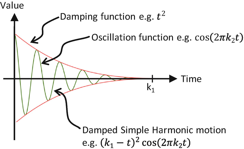
Consider how a camera shake may occur in a real-life situation. For instance, while shooting with a video camera, say you are surprised or startled by someone or that something collided with you. Your reaction will probably be slight disorientation followed by quickly refocusing on the original targets. From the perspective of the camera, this reaction can be described as an initial large displacement from the original camera center followed by quick adjustments to re-center the camera. Mathematically, as illustrated in Figure 7-6, damped simple harmonic motions, which can be represented with the damping of trigonometric functions, can be used to describe these types of displacements.
The displacements of a damped simple harmonic motion
The Camera Shake and Object Oscillate Project

Running the Camera Shake and Object Oscillate project
Q key: Initiates the positional oscillation of the Dye character and the camera shake effects.
WASD keys: Move the Dye character (the Hero object). Notice that the camera WC window updates to follow the Hero object when it attempts to move beyond 90 percent of the WC bounds.
Arrow keys: Move the Portal object. Notice that the Portal object cannot move beyond 80 percent of the WC bounds.
L/R/P/H keys: Select the Left minion, Right minion, Portal object, or Hero object to be the object in focus. The L/R keys also set the camera to focus on the Left or Right minion.
N/M keys: Zoom into or away from the center of the camera.
J/K keys: Zoom into or away while ensuring constant relative position of the currently in-focus object. In other words, as the camera zooms, the positions of all objects will change except that of the in-focus object.
To gain some insight into modeling displacements with simple mathematical functions
To experience the oscillate effect on an object
To experience the shake effect on a camera
To implement oscillations as damped simple harmonic motion and to introduce pseudo-randomness to create the camera shake effect
As in previous projects, you can find external resource files in the assets folder.
Abstract the Shake Behavior
Oscillate: The base class that implements simple harmonic oscillation of a value over time
Shake: An extension of the Oscillate class that introduces randomness to the magnitudes of the oscillations to simulate slight chaos of the shake effect on a value
ShakeVec2: An extension of the Shake class that expands the Shake behavior to two values such as a position
Create the Oscillate Class to Model Simple Harmonic Motion
- 1.
Create a new file in the src/engine/utils folder and name it oscillate.js. Define a class named Oscillate and add the following code to construct the object:
- 2.
Define the damped simple harmonic motion:
 , is the damping factor. This function returns a value between -1 and 1 and can be scaled as needed.
The damped simple harmonic motion that specifies value oscillation
- 3.
Define a protected function to retrieve the value of the next damped harmonic motion. This function may seem trivial and unnecessary. However, as you will observe in the next subsection, this function allows a shake subclass to overwrite and inject randomness.
- 4.
Define functions to check for the end of the oscillation and for restarting the oscillation:
- 5.
Lastly, define a public function to trigger the calculation of oscillation. Notice that the computed oscillation result must be scaled by the desired magnitude, mMag:
Create the Shake Class to Randomize an Oscillation
You can now extend the oscillation behavior to convey a sense of shaking by introducing pseudo-randomness into the effect .
- 1.
Create a new file, shake.js, in the src/engine/utils folder. Define the Shake class to extend Oscillate and add the following code to construct the object:
- 2.
Overwrite the _nextValue() to randomize the sign of the oscillation results as follows. Recall that the _nextValue() function is called from the public getNext() function to retrieve the oscillating value. While the results from the damped simple harmonic oscillation continuously and predictably decrease in magnitude, the associated signs of the values are randomized causing sudden and unexpected discontinuities conveying a sense of chaos from the results of a shake.
Create the ShakeVec2 Class to Model the Shaking of a vec2, or a Position
You can now generalize the shake effect to support the shaking of two values simultaneously. This is a useful utility because positions in 2D games are two-value entities and positions are convenient targets for shake effects. For example, in this project, the shaking of the camera position, a two-value entity, simulates the camera shake effect.
- 1.
Create a new file, shake_vec2.js, in the src/engine/utils folder. Define the ShakeVec2 class to extend the Shake class. Similar to the constructor parameters of the Shake super classes, the deltas and freqs parameters are 2D, or vec2, versions of magnitude and frequency for shaking in the x and y dimensions. In the constructor, the xShake instance variable keeps track of shaking effect in the x dimension. Note the y-component parameters, array indices of 1, in the super() constructor invocation. The Shake super class keeps track of the shaking effect in the y dimension.
- 2.
Extend the reStart() and getNext() functions to support the second dimension:
Lastly, remember to update the engine access file, index.js, to forward the newly defined Oscillate, Shake, and ShakeVec2 functionality to the client.
Define the CameraShake Class to Abstract the Camera Shaking Effect
- 1.
Create a new file, camera_shake.js, in the src/engine/cameras folder, and define the constructor to receive the camera state, the state parameter, and shake configurations: deltas, freqs, and shakeDuration. The parameter state is of datatype CameraState, consisting of the camera center position and width.
- 2.
Define the function that triggers the displacement computation for accomplishing the shaking effect. Notice that the shake results are offsets from the original position. The given code adds this offset to the original camera center position.
- 3.
Define utility functions: inquire if shaking is done, restart the shaking, and getter/setter functions.
Similar to CameraState, CameraShake is also a game engine internal utility and should not be exported to the client game programmer. The engine access file, index.js, should not be updated to export this class.
Modify the Camera to Support Shake Effect
- 1.
Modify camera_main.js and camera_manipulation.js to import camera_shake.js as shown:
- 2.
In camera_main.js, modify the Camera constructor to initialize a CameraShake object:
- 3.
Modify step B of the setViewAndCameraMatrix() function to use the CameraShake object’s center if it is defined:
- 4.
Modify the camera_manipulation.js file to add support to initiate and restart the shake effect:
- 5.
Continue working with the camera_manipulation.js file, and modify the update() function to trigger a camera shake update if one is defined:
Testing the Camera Shake and Oscillation Effects in MyGame
- 1.
Define a new instance variable for creating oscillation or bouncing effect on the Dye character:
- 2.
Modify the update() function to trigger the bouncing and camera shake effects with the Q key. In the following code, note the advantage of well-designed abstraction. For example, the camera shake effect is opaque where the only information a programmer needs to specify is the actual shake behavior, that is, the shake magnitude, frequency, and duration. In contrast, the oscillating or bouncing effect of the Dye character position is accomplished by explicitly inquiring and using the mBounce results.
You can now run the project and experience the pseudo-random damped simple harmonic motion that simulates the camera shake effect. You can also observe the oscillation of the Dye character’s x position. Notice that the displacement of the camera center position will undergo interpolation and thus result in a smoother final shake effect. You can try changing the parameters when creating the mBounce object or when calling the mCamera.shake() function to experiment with different oscillation and shake configurations. Recall that in both cases the first two parameters control the initial displacements and the frequency (number of cosine periods) and the third parameter is the duration of how long the effects should last.
Multiple Cameras
Video games often present the players with multiple views into the game world to communicate vital or interesting gameplay information, such as showing a mini-map to help the player navigate the world or providing a view of the enemy boss to warn the player of what is to come.
In your game engine, the Camera class abstracts the graphical presentation of the game world according to the source and destination areas of drawing. The source area of the drawing is the WC window of the game world, and the destination area is the viewport region on the canvas. This abstraction already effectively encapsulates and supports the multiple view idea with multiple Camera instances. Each view in the game can be handled with a separate instance of the Camera object with distinct WC window and viewport configurations.
The Multiple Cameras Project
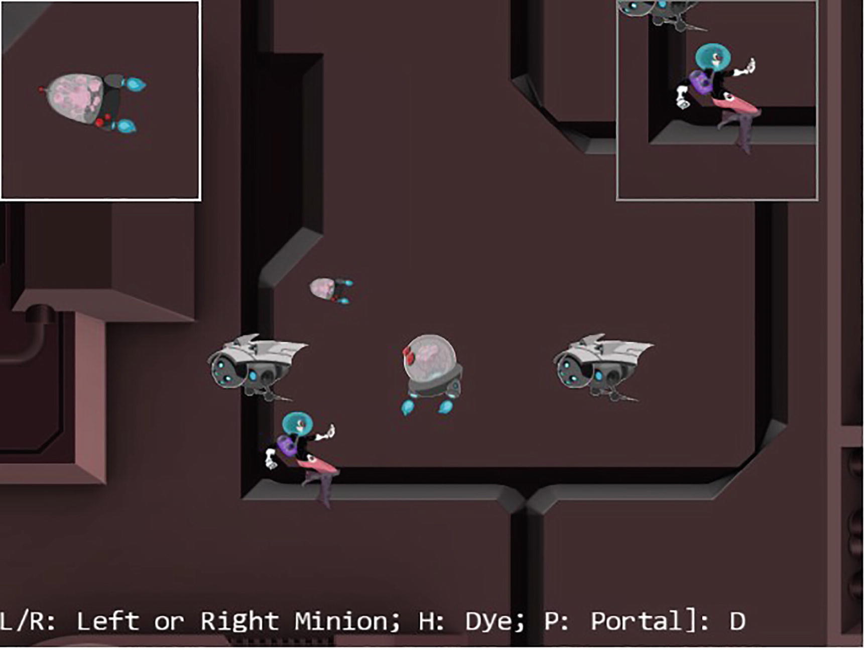
Running the Multiple Cameras project
Q key: Initiates the positional oscillation of the Dye character and the camera shake effects.
WASD keys: Move the Dye character (the Hero object). Notice that the camera WC window updates to follow the Hero object when it attempts to move beyond 90 percent of the WC bounds.
Arrow keys: Move the Portal object. Notice that the Portal object cannot move beyond 80 percent of the WC bounds.
L/R/P/H keys: Select the Left minion, Right minion, Portal object, or Hero object to be the object in focus. The L/R keys also set the camera to focus on the Left or Right minion.
N/M keys: Zoom into or away from the center of the camera.
J/K keys: Zoom into or away while ensuring the constant relative position of the currently in-focus object. In other words, as the camera zooms, the positions of all objects will change except that of the in-focus object.
To understand the camera abstraction for presenting views into the game world
To experience working with multiple cameras in the same game level
To appreciate the importance of interpolation configuration for cameras with specific purposes
As in previous projects, you can find external resource files in the assets folder.
Modify the Camera
- 1.
Edit camera_main.js and modify the Camera constructor to allow programmers to define a bound number of pixels to surround the viewport of the camera:
- 2.
Define the setViewport() function :
- 3.
Define the getViewport() function to return the actual bounds that are reserved for this camera. In this case, it is the mScissorBound instead of the potentially smaller viewport bounds.
- 4.
Modify the setViewAndCameraMatrix() function to bind scissor bounds with mScissorBound instead of the viewport bounds:
Testing Multiple Cameras in MyGame
- 1.
Modify the init() function to define three Camera objects. Both the mHeroCam and mBrainCam define a two-pixel boundary for their viewports, with the mHeroCam boundary defined to be gray (the background color) and with mBrainCam white. Notice the mBrainCam object’s stiff interpolation setting informing the camera interpolation to converge to new values in ten cycles.
- 2.
Define a helper function to draw the world that is common to all three cameras:
- 3.
Modify the MyGame object draw() function to draw all three cameras. Take note of the mMsg object only being drawn to mCamera, the main camera. For this reason, the echo message will appear only in the viewport of the main camera.
- 4.
Modify the update() function to pan the mHeroCam and mBrainCam with the corresponding objects and to move the mHeroCam viewport continuously:
Viewports typically do not change their positions during gameplays. For testing purposes, the following code moves the mHeroCam viewport continuously from left to right in the canvas.
You can now run the project and notice the three different viewports displayed on the HTML canvas. The two-pixel-wide bounds around the mHeroCam and mBrainCam viewports allow easy visual parsing of the three views. Observe that the mBrainCam viewport is drawn on top of the mHeroCam. This is because in the MyGame.draw() function , the mBrainCam is drawn last. The last drawn object always appears on the top. You can move the Hero object to observe that mHeroCam follows the hero and experience the smooth interpolated results of panning the camera.
Now try changing the parameters to the mBrainCam.configLerp() function to generate smoother interpolated results, such as by setting the stiffness to 0.1 and the duration to 100 cycles. Note how it appears as though the camera is constantly trying to catch up to the Brain object. In this case, the camera needs a stiff interpolation setting to ensure the main object remains in the center of the camera view. For a much more drastic and fun effect, you can try setting mBrainCam to have much smoother interpolated results, such as with a stiffness value of 0.01 and a duration of 200 cycles. With these values, the camera can never catch up to the Brain object and will appear as though it is wandering aimlessly around the game world.
Mouse Input Through Cameras
The mouse is a pointing input device that reports position information in the Canvas Coordinate space. Recall from the discussion in Chapter 3 that the Canvas Coordinate space is simply a measurement of pixel offsets along the x/y axes with respect to the lower-left corner of the canvas. Remember that the game engine defines and works with the WC space where all objects and measurements are specified in WC. For the game engine to work with the reported mouse position, this position must be transformed from Canvas Coordinate space to WC.
mouseDCX = mouseX − Vx
mouseDCY = mouseY − Vy

Mouse position on canvas and viewport


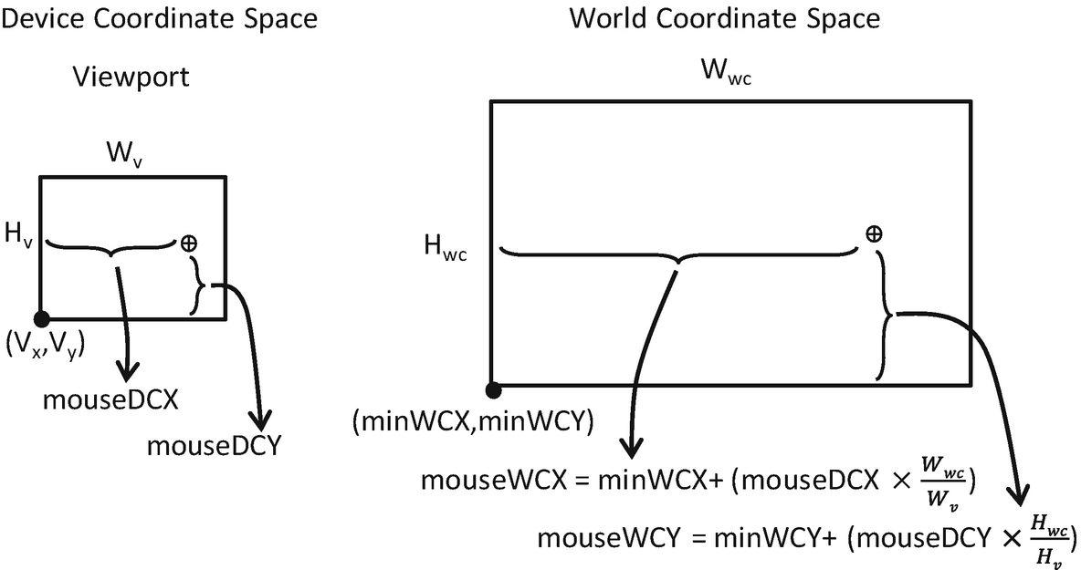
Mouse position in viewport DC space and WC space
With the knowledge of how to transform positions from the Canvas Coordinate space to the WC space, it is now possible to implement mouse input support in the game engine.
The Mouse Input Project

Running the Mouse Input project
Left mouse button clicked in the main Camera view: Drags the Portal object
Middle mouse button clicked in the HeroCam view: Drags the Hero object
Right/middle mouse button clicked in any view: Hides/shows the Portal object
Q key: Initiates the positional oscillation of the Dye character and the camera shake effects
WASD keys: Move the Dye character (the Hero object) and push the camera WC bounds
Arrow keys: Move the Portal object
L/R/P/H keys: Select the in-focus object with L/R keys refocusing the camera to the Left or Right minion
N/M and J/K keys: Zoom into or away from the center of the camera or the in-focus object
To understand the Canvas Coordinate space to WC space transform
To appreciate the importance of differentiating between viewports for mouse events
To implement transformation between coordinate spaces
To support and experience working with mouse input
As in previous projects, you can find external resource files in the assets folder.
Modify index.js to Pass Canvas ID to Input Component
Implement Mouse Support in input.js
- 1.
Edit input.js and define the constants to represent the three mouse buttons:
- 2.
Define the variables to support mouse input. Similar to keyboard input, mouse button states are arrays of three boolean elements, each representing the state of the three mouse buttons.
- 3.
Define the mouse movement event handler:
- 4.
Define the mouse button click handler to record the button event:
- 5.
Define the mouse button release handler to facilitate the detection of a mouse button click event. Recall from the keyboard input discussion in Chapter 4 that in order to detect the button up event, you should test for a button state that was previously released and currently clicked. The mouseUp() handler records the released state of a mouse button.
- 6.
Modify the init() function to receive the canvasID parameter and initialize mouse event handlers:
- 7.
Modify the update() function to process mouse button state changes in a similar fashion to the keyboard. Take note of the mouse-click condition that a button that was previously not clicked is now clicked.
- 8.
Define the functions to retrieve mouse position and mouse button states:
- 9.
Lastly, remember to export the newly defined functionality:
Modify the Camera to Support Viewport to WC Space Transform
The Camera class encapsulates the WC window and viewport and thus should be responsible for transforming mouse positions. Recall that to maintain readability, the Camera class source code files are separated according to functionality. The basic functions of the class are defined in camera_main.js. The camera_manipulate.js file imports from camera_main.js and defines additional manipulation functions. Lastly, the camera.js file imports from camera_manipulate.js to include all the defined functions and exports the Camera class for external access.
- 1.Create a new file in the src/engine/cameras folder and name it camera_input.js. This file will expand the Camera class by defining the mouse input support functions. Import the following files:
camera_manipulation.js for all the defined functions for the Camera class
eViewport constants for accessing the viewport array
input module to access the mouse-related functions
- 2.
Define functions to transform mouse positions from Canvas Coordinate space to the DC space, as illustrated in Figure 7-10:
- 3.
Define a function to determine whether a given mouse position is within the viewport bounds of the camera:
- 4.
Define the functions to transform the mouse position into the WC space, as illustrated in Figure 7 11:
Testing the Mouse Input in MyGame
The camera.isMouseInViewport() condition is checked when the viewport context is important, as in the case of a left mouse button click in the main camera view or a middle mouse button click in the mHeroCam view. This is in contrast to a right or middle mouse button click for setting the visibility of the Portal object. These two mouse clicks will cause execution no matter where the mouse position is.
You can now run the project and verify the correctness of the transformation to WC space. Click and drag with left mouse button in the main view, or middle mouse button in the mHeroCam view, to observe the accurate movement of the corresponding object as they follow the changing mouse position. The left or middle mouse button drag actions in the wrong views have no effect on the corresponding objects. For example, a left mouse button drag in the mHeroCam or mBrainCam view has no effect on the Portal object. However, notice that the right or middle mouse button click controls the visibility of the Portal object, independent of the location of the mouse pointer. Be aware that the browser maps the right mouse button click to a default pop-up menu. For this reason, you should avoid working with right mouse button clicks in your games.
Summary
This chapter was about controlling and interacting with the Camera object. You have learned about the most common camera manipulation operations including clamping, panning, and zooming. These operations are implemented in the game engine with utility functions that map the high-level specifications to actual WC window bound parameters. The sudden, often annoying, and potentially confusing movements from camera manipulations are mitigated with the introduction of interpolation. Through the implementation of the camera shake effect, you have discovered that some movements can be modeled by simple mathematical formulations. You have also experienced the importance of effective Camera object abstraction in supporting multiple camera views. The last section guided you through the implementation of transforming a mouse position from the Canvas Coordinate space to the WC space.
In Chapter 5, you found out how to represent and draw an object with a visually appealing image and control the animation of this object. In Chapter 6, you read about how to define an abstraction to encapsulate the behaviors of an object and the fundamental support required to detect collisions between objects. This chapter was about the “directing” of these objects: what should be visible, where the focus should be, how much of the world to show, how to ensure smooth transition between foci, and how to receive input from the mouse. With these capabilities, you now have a well-rounded game engine framework that can represent and draw objects, model and manage the behaviors of the objects, and control how, where, and what objects are shown.
The following chapters will continue to examine object appearance and behavior at more advanced levels, including creating lighting and illumination effects in a 2D world and simulating and integrating behaviors based on simple classical mechanics.
Game Design Considerations
You’ve learned the basics of object interaction, and it’s a good time to start thinking about creating your first simple game mechanic and experimenting with the logical conditions and rules that constitute well-formed gameplay experiences. Many designers approach game creation from the top-down (meaning they start with an idea for an implementation of a specific genre like a real-time strategy, tower defense, or role-playing game), which we might expect in an industry like video games where the creators typically spend quite a bit of time as content consumers before transitioning into content makers. Game studios often reinforce this top-down design approach, assigning new staff to work under seasoned leads to learn best practices for whatever genre that particular studio works in. This has proven effective for training designers who can competently iterate on known genres, but it’s not always the best path to develop well-rounded creators who can design entirely new systems and mechanics from the ground-up.
The aforementioned might lead us to ask, “What makes gameplay well formed?” At a fundamental level, a game is an interactive experience where rules must be learned and applied to achieve a specified outcome; all games must meet this minimum criterion, including card, board, physical, video, and other game types. Taking it a step further, a good game is an interactive experience with rules people enjoy learning and applying to achieve an outcome they feel invested in. There’s quite a bit to unpack in this brief definition, of course, but as a general rule, players will enjoy a game more when the rules are discoverable, consistent, and make logical sense and when the outcome feels like a satisfactory reward for mastering those rules. This definition applies to both individual game mechanics and entire game experiences. To use a metaphor, it can be helpful to think of game designs as being built with letters (interactions) that form words (mechanics) that form sentences (levels) that ultimately form readable content (genres). Most new designers attempt to write novels before they know the alphabet, and everyone has played games where the mechanics and levels felt at best like sentences written with poor grammar and at worst like unsatisfying, random jumbles of unintelligible letters.
Over the next several chapters, you’ll learn about more advanced features in 2D game engines, including simulations of illumination and physical behaviors. You’ll also be introduced to a set of design techniques enabling you to deliver a complete and well-formed game level, integrating these techniques and utilizing more of the nine elements of game design discussed in Chapter 4 in an intentional way and working from the ground-up to deliver a unified experience. In the earliest stages of design exploration, it’s often helpful to focus only on creating and refining the basic game mechanics and interaction model; at this stage, try to avoid thinking about setting, meta-game, systems design, and the like (these will be folded into the design as it progresses).
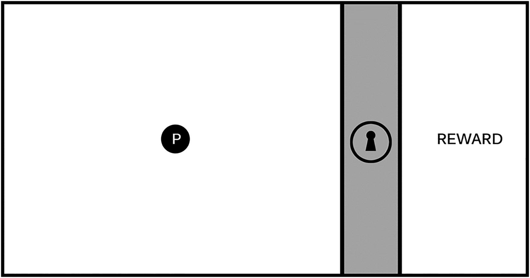
The image represents a single game screen divided into three areas. A playable area on the left with a hero character (the circle marked with a P), an impassable barrier marked with a lock icon, and a reward area on the right
The screen represented in Figure 7-13 is a useful starting place when exploring new mechanics. The goal for this exercise is to create one logical challenge that a player must complete to unlock the barrier and reach the reward. The specific nature of the task can be based on a wide range of elemental mechanics: it might involve jumping or shooting, puzzle solving, narrative situations, or the like. The key is to keep this first iteration simple (this first challenge should have a limited number of components contributing to the solution) and discoverable (players must be able to experiment and learn the rules of engagement so they can intentionally solve the challenge). You’ll add complexity and interest to the mechanic in later iterations, and you’ll see how elemental mechanics can be evolved to support many kinds of game types.
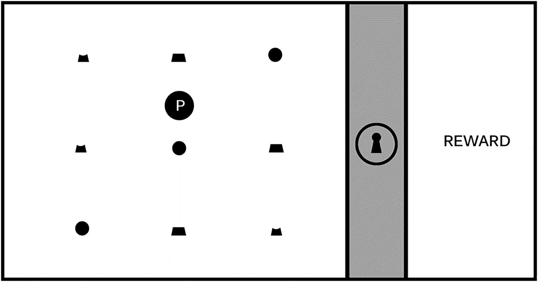
The game screen is populated with an assortment of individual objects
As the player moves the hero character around the game screen, the shapes “activate” with a highlight (#1); activating certain shapes causes a section of the lock and one-third of the surrounding ring to glow (#2)
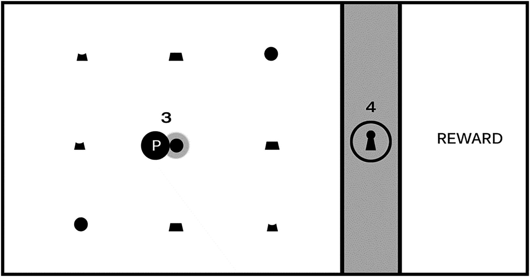
Activating some shapes (#3) will not cause the lock and ring to glow (#4)
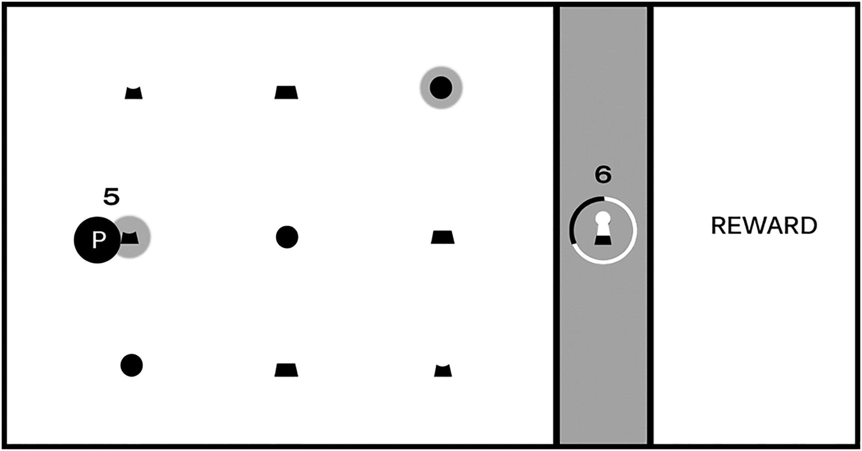
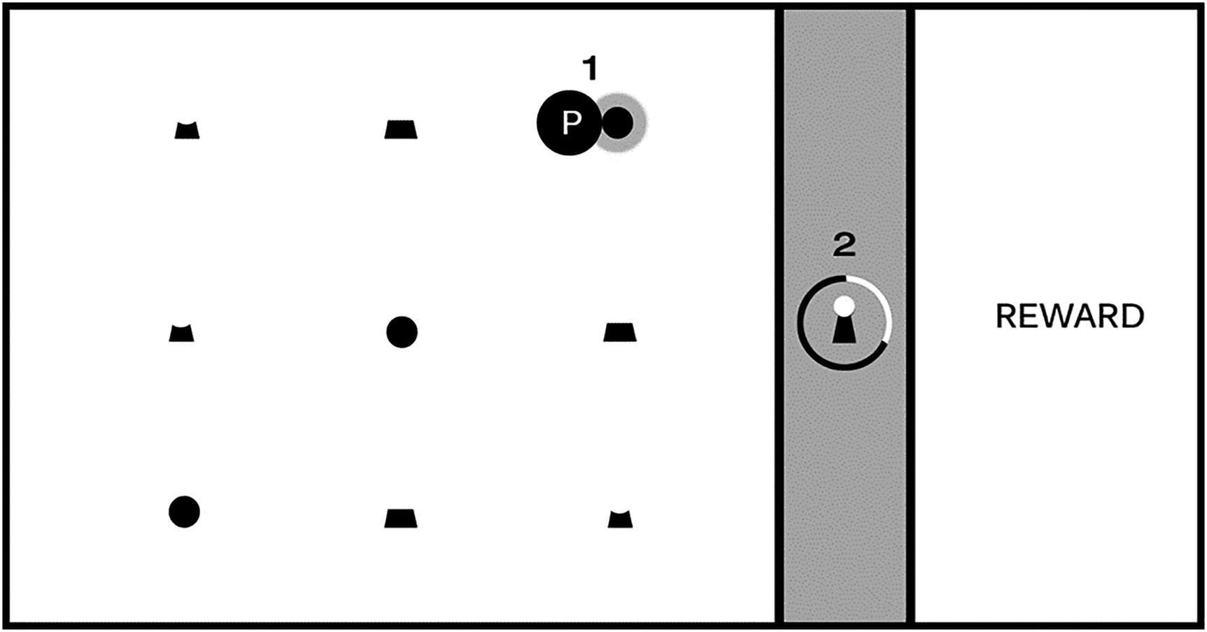
After the first object was activated (the circle in the upper right) and caused the top section of the lock and first third of the ring to glow, as shown in Figure 7-15, the second object in the correct sequence (#5) caused the middle section of the lock and second third of the ring to glow (#6)
You (and players) should now have all required clues to learn the rules of this mechanic and solve the puzzle. There are three shapes the player can interact with and only one instance of each shape per row; the shapes are representations of the top, middle, and bottom of the lock icon, and as shown in Figure 7-15, activating the circle shape caused the corresponding section of the lock to glow. Figure 7-16, however, did not cause the corresponding section of the lock to glow, and the difference is the “hook” for this mechanic: sections of the lock must be activated in the correct relative position: top in the top row, middle in the middle row, bottom on the bottom (you might also choose to require that players activate them in the correct sequence starting with the top section, although that requirement is not discoverable just from looking at Figures 7-15 to 7-17).
Congratulations, you’ve now created a well-formed and logically consistent (if simple) puzzle, with all of the elements needed to build a larger and more ambitious level! This unlocking sequence is a game mechanic without narrative context: the game screen is intentionally devoid of game setting, visual style, or genre alignment at this stage of design because we don’t want to burden our exploration yet with any preconceived expectations. It can benefit you as a designer to spend time exploring game mechanics in their purest form before adding higher-level game elements like narrative and genre, and you’ll likely be surprised at the unexpected directions, these simple mechanics will take you as you build them out.
Simple mechanics like the one in this example can be described as “complete a multistage task in the correct sequence to achieve a goal” and are featured in many kinds of games; any game that requires players to collect parts of an object and combine them in an inventory to complete a challenge, for example, utilizes this mechanic. Individual mechanics can also be combined with other mechanics and game features to form compound elements that add complexity and flavor to your game experience.
The camera exercises in this chapter provide good examples for how you might add interest to a single mechanic; the simple Camera Manipulations project, for example, demonstrates a method for advancing game action. Imagine in the previous example that after a player receives a reward for unlocking the barrier, they move the hero object to the right side of the screen and advance to a new “room” or area. Now imagine how gameplay would change if the camera advanced the screen at a fixed rate when the level started; the addition of autoscrolling changes this mechanic considerably because the player must solve the puzzle and unlock the barrier before the advancing barrier pushes the player off the screen. The first instance creates a leisurely puzzle-solving game experience, while the latter increases the tension considerably by giving the player a limited amount of time to complete each screen. In an autoscrolling implementation, how might you lay out the game screen to ensure the player had sufficient time to learn the rules and solve the puzzle?
The Multiple Cameras project can be especially useful as a mini-map that provides information about places in the game world not currently displayed on the game screen; in the case of the previous exercise, imagine that the locked barrier appeared somewhere else in the game world other than the player’s current screen and that a secondary camera acting as a mini-map displayed a zoomed out view of the entire game world map. As the game designer, you might want to let the player know when they complete a task that allows them to advance and provide information about where they need to go next, so in this case, you might flash a beacon on the mini-map calling attention to the barrier that just unlocked and showing the player where to go. In the context of our “game design is like a written language” metaphor, adding additional elements like camera behavior to enhance or extend a simple mechanic is one way to begin forming “adjectives” that add interest to the basic nouns and verbs we’ve been creating from the letters in the game design alphabet.
A game designer’s primary challenge is typically to create scenarios that require clever experimentation while maintaining logical consistency; it’s perfectly fine to frustrate players by creating devious scenarios requiring creative problem solving (we call this “good” frustration), but it’s generally considered poor design to frustrate players by creating scenarios that are logically inconsistent and make players feel that they succeeded in a challenge only by random luck (“bad” frustration). Think back to the games you’ve played that have resulted in bad frustration: where did they go wrong, and what might the designers have done to improve the experience?
The locked room scenario is a useful design tool because it forces you to construct basic mechanics, but you might be surprised at the variety of scenarios that can result from this exercise. Try a few different approaches to the locked room puzzle and see where the design process takes you, but keep it simple. For now, stay focused on one-step events to unlock the room that require players to learn only one rule. You’ll revisit this exercise in the next chapter and begin creating more ambitious mechanics that add additional challenges.