
Chapter 8: Building R2-D2
Who isn't a Star Wars fan here? As a child, I would make sure to watch the latest offerings from Star Wars on the very first day of release. One of the reasons to love Star Wars is the number of crazy and fancy robots in the movie and the kinds of special actions they do. Of all these robots, I really loved R2-D2 from day 1. Its movement and unique design with a rotating head have always kept me glued to the character. Which is your favorite Star Wars robot? In this chapter, you will be building an R2-D2 robot and solving fun programming tasks:

Figure. 8.1 – R2-D2 robot from Star Wars
Let's first understand what a pulley is and how it works. A pulley is one of six simple machines used to make our pulling efforts easy. Some common applications of pulleys are as follows:
- Curtains/blinds: A pulley is used to open and close the blinds and helps in pulling the curtains up and down.
- Flower basket: A pulley mechanism holds the flower basket, and we can easily lower it when we want to flower the plants.
- Ropeways.
- Rock climbing equipment.
Like a gear, a pulley system also has a drive and a driven pulley. In your robot, the pulley attached to the neck of R2-D2 will be a driven pulley:

Figure 8.2 – Pulley mechanism (reference image for designer)
This chapter will cover the following areas:
- Building the R2-D2 robot.
- Let's code the robot to move on a specific path
- Time for a challenge.
In this robot, you will be using a single motor drive that will not allow you to make turns. You will be using a pulley mechanism to rotate the head of your R2-D2.
Technical requirements
In this chapter, you will need the following:
- A LEGO BOOST kit with six AAA batteries, fully charged
- A laptop/desktop with Scratch 3.0 programming and an active internet connection
- A diary/notebook with a pencil and eraser
Building the R2-D2 robot
Let's build the following robot:
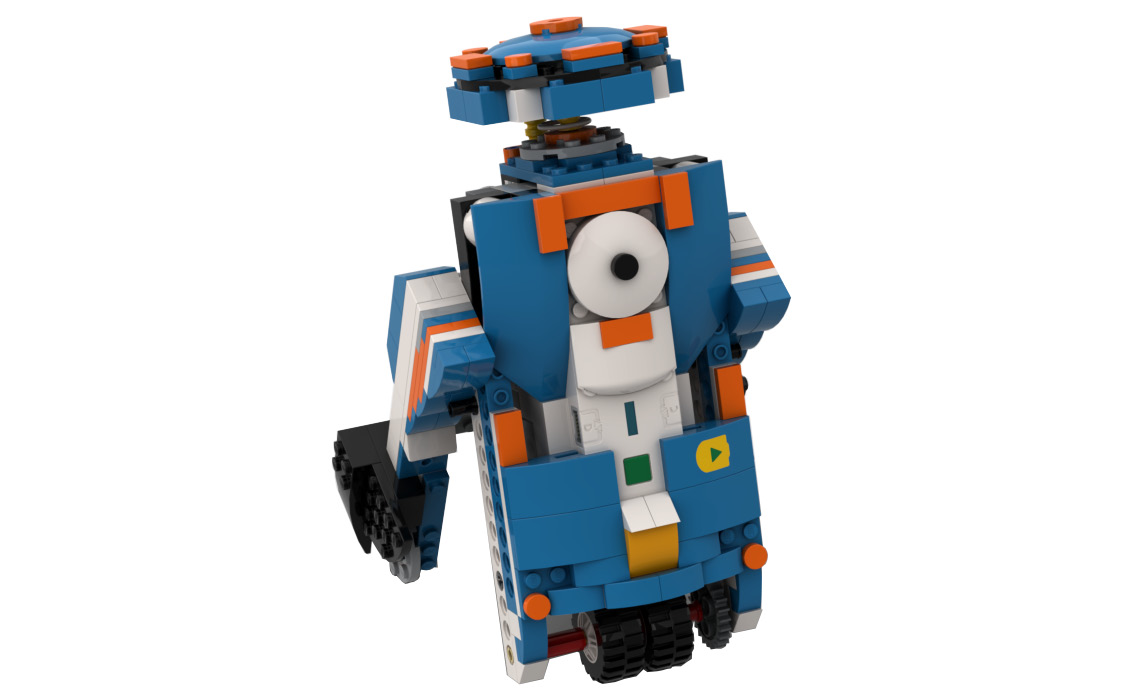
Figure 8.3 – R2-D2 robot using the BOOST kit
We will use the following building instructions:
- Take your BOOST Hub. Ensure that the batteries are fully charged:

Figure 8.4
- Take two 1x2 bricks with a horizontal snap and connect them to the BOOST Hub:
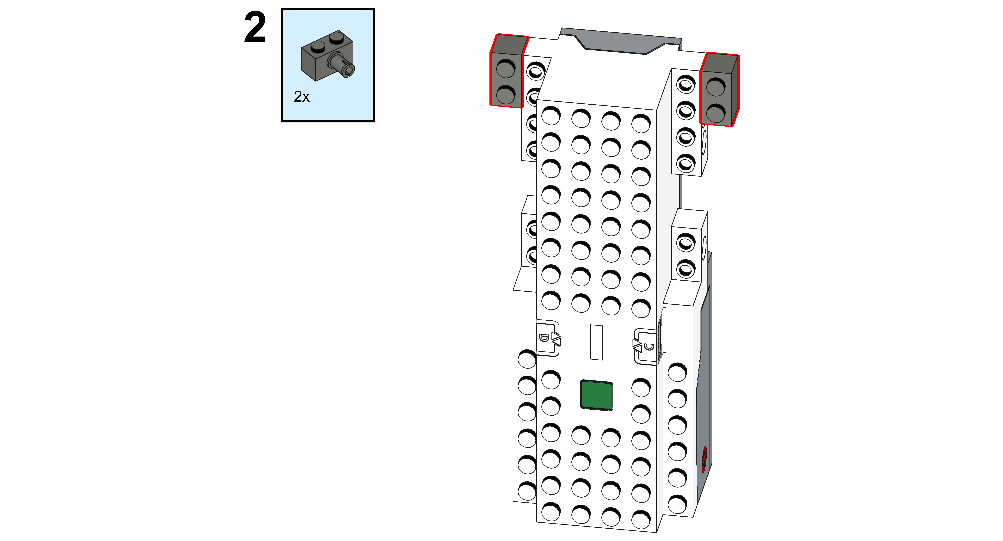
Figure 8.5
- Take two 2x2 round plates and connect them to the back side of the BOOST Hub as shown in the following figure:

Figure 8.6
- Now take two 1x6 bricks with a bow and two 1x11 Technic bricks. Connect them to the BOOST Hub, one above the other:
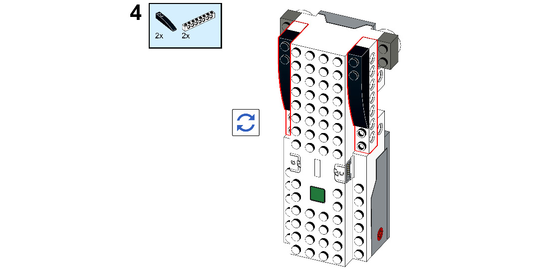
Figure 8.7
- Take two 2x6 bricks with a bow, one 2M cross axle, and one 1x1 beam. Connect the 2x6 bricks with a bow to the 1x2 bricks and 2M cross axle in motor A of the BOOST Hub, then insert a 1x1 beam:
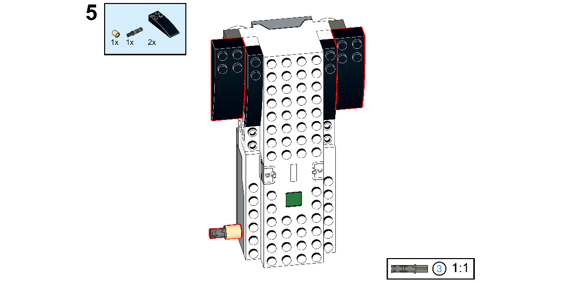
Figure 8.8
- Take two 1x16 Technic bricks and connect them to the back side of the 2x6 brick with a bow, as shown in the following figure:
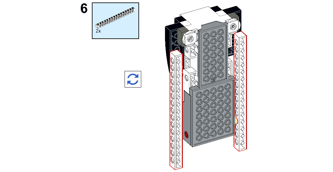
Figure 8.9
- Take one 3M stopper axle and one 24-tooth spur gear. Connect the spur gear to motor B of the BOOST Hub, then insert the 3M stopper axle onto it:

Figure 8.10
- Take one full bushing, one 5M stopper axle, and one 24-tooth spur gear. Connect the 5M stopper axle to the 15th hole of the Technic brick, then connect the 24-tooth spur gear and full bushing to it, as shown here:

Figure 8.11
- Take one wheel and connect it to the recently attached 5M stopper axle:
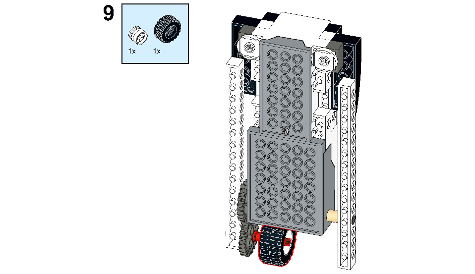
Figure 8.12
- Take one cross axle extension. Connect it to the recently attached 5M stopper axle after the wheel:
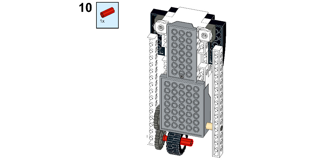
Figure 8.13
- Take one 3M axle. Connect it to the cross-axle extension:
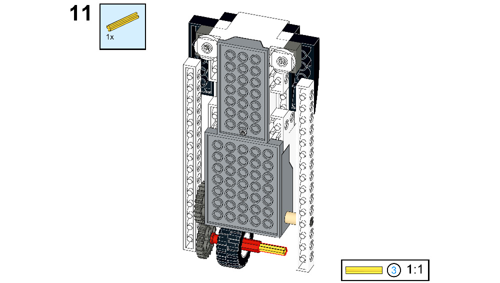
Figure 8.14
- Take one wheel and connect it to the recently attached 3M axle:
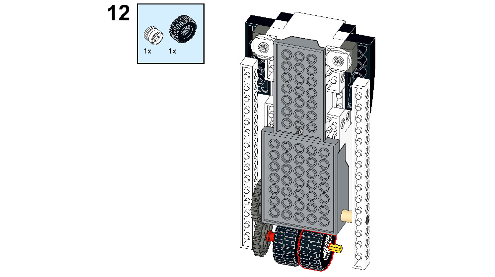
Figure 8.15
- Take one connector peg with a cross axle and one cross axle extension. Connect it to the 3M axle as shown in the following figure:

Figure 8.16
- Take two 1x10 Technic bricks and connect them to the 1x16 Technic brick as shown in the following figure:

Figure 8.17
- Take two 1x1 beams and two 1x2 roof tiles. Connect them to the 1x16 Technic brick as shown in the following figure:
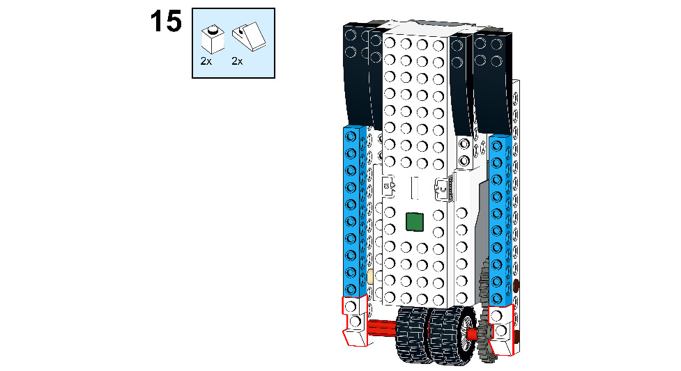
Figure 8.18
- Now, take two 1x1 plates and two 1x11 plates. Connect the 1x11 plate to the recently attached 1x10 Technic brick and connect the 1x1 plate to the 1x2 roof tile:
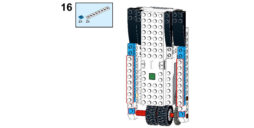
Figure 8.19
- Take two 1x2x2/3 plates with a bow. Connect them to the recently attached 1x1 plate and 1x1 beam:
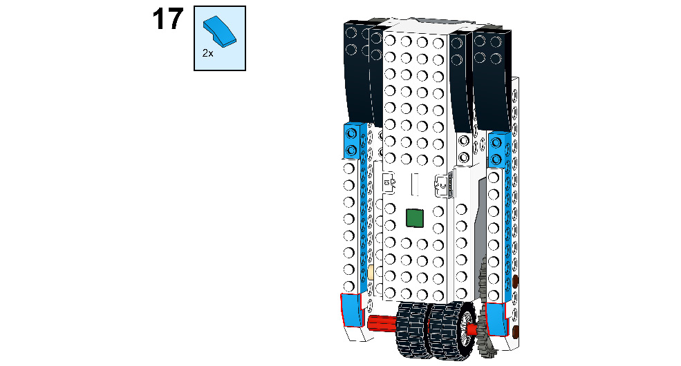
Figure 8.20
- Now, take two 2x2 round bricks. Connect them to the 2x6 brick with a bow:
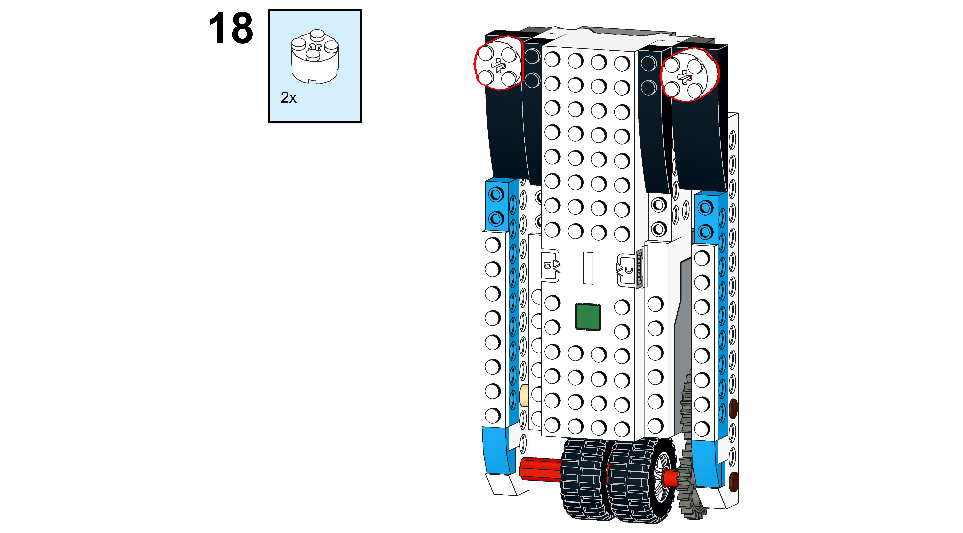
Figure 8.21
- Take two 1x2 angle plates. Connect them to the top of the BOOST Hub as shown in the following figure:
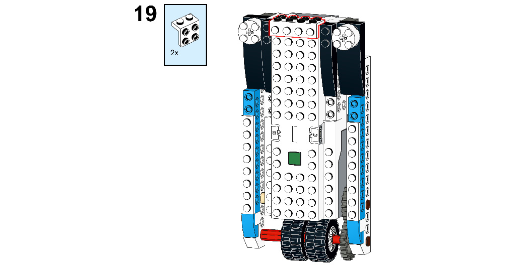
Figure 8.22
- Now, take one 1x4 plate. Connect it to the back side of the recently attached 1x2 angle plate:

Figure 8.23
- Take two 1x2 1.5-bot angular plates. Connect them to the recently attached 1x4 plate:
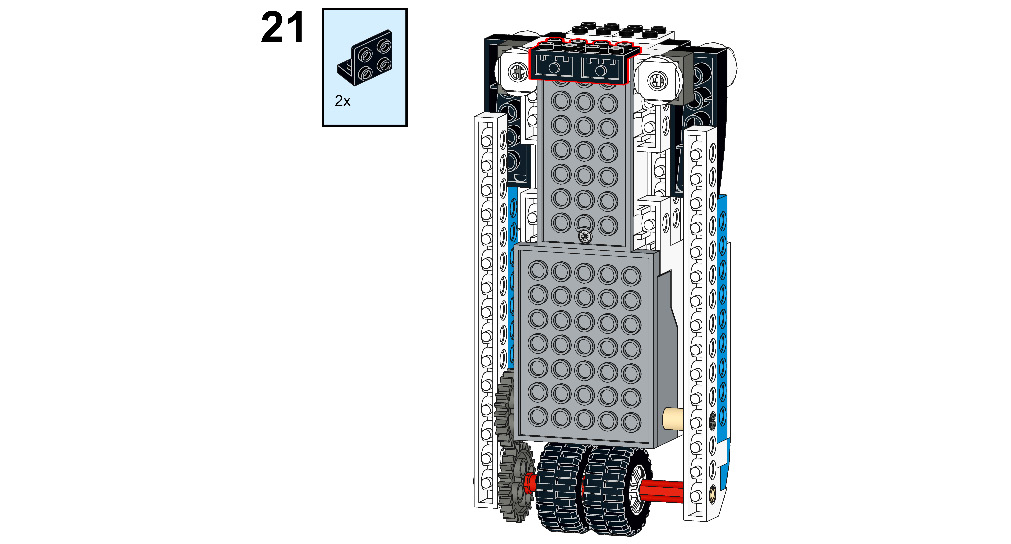
Figure 8.24
- Take two 2x6 plates. Connect them to the top of the 1x2 1.5-bot angular plate and the 1X2 angle plate as shown in the following figure:

Figure 8.25
- Take four 1x2 plates. Connect them to the 2x6 plate as shown in the following figure:

Figure 8.26
- Take one 3M axle and one 4x4 round plate. Connect the 3M axle to the 4x4 round plate, then connect it to the recently attached 1x2 plate:
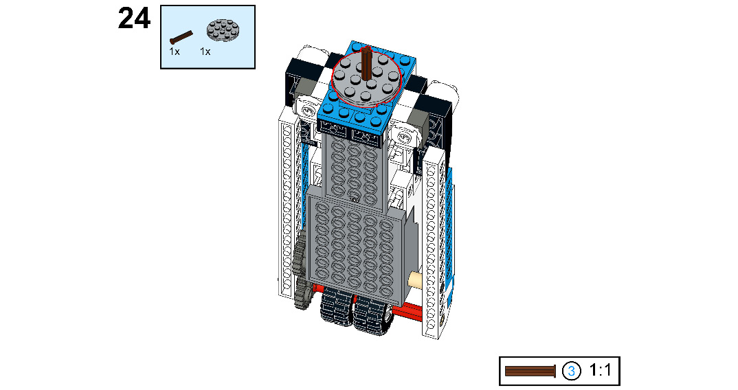
Figure 8.27
- Take two half bushings and one 2x2 flat tile. First, connect the flat tile to the 2x2 angular plate, and then connect the half bushings through the axle:
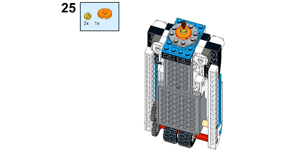
Figure 8 28
- Take one 3x11x2 left shell and one 3x11x2 right shell. Connect them to the 1x6 brick with a bow as shown in the following figure:
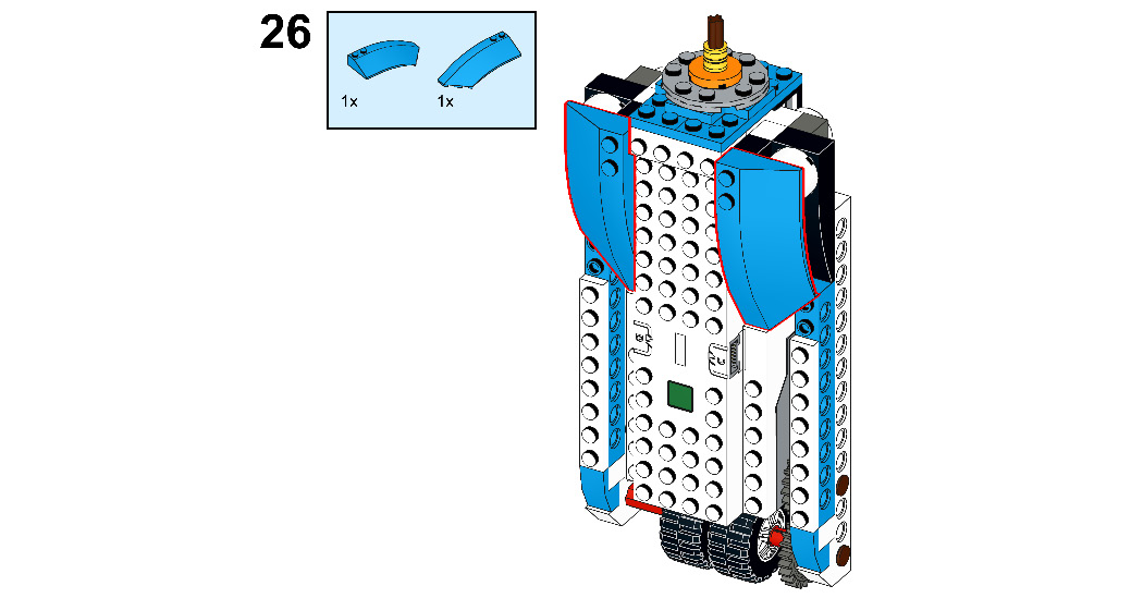
Figure 8.29
- Take two 1x2 flat tiles and one 1x4 flat tile. Connect the 1x4 flat tile to the 1x2 angle plate and the 1x2 flat tiles to the 3x11x2 left shell and the 3x11x2 right shell:

Figure 8.30
- Now, take one 4x4 round plate. Connect it to the BOOST Hub as shown in the following figure:
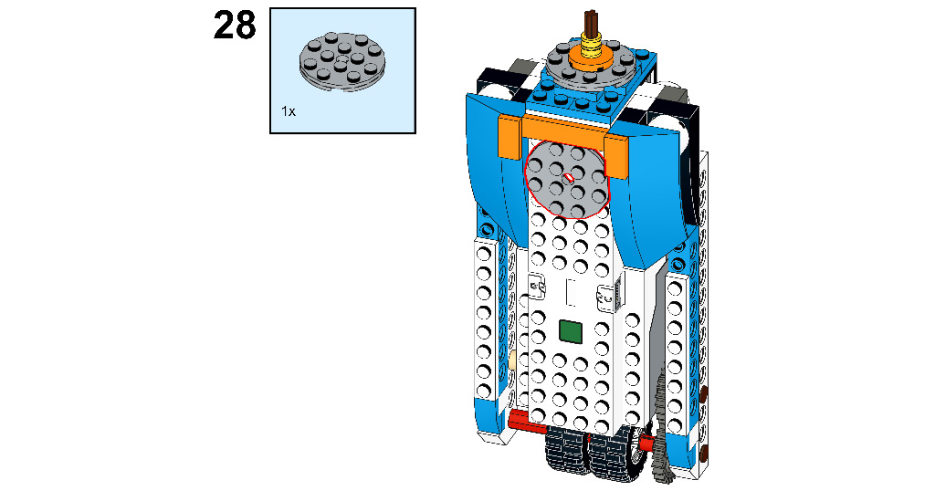
Figure 8.31
- Take one 3x4x2 plate with a bow and one round plate. Connect the round plate to the 4x4 round plate and the 3x4x2 plate with a bow to the BOOST Hub as shown in the following figure:
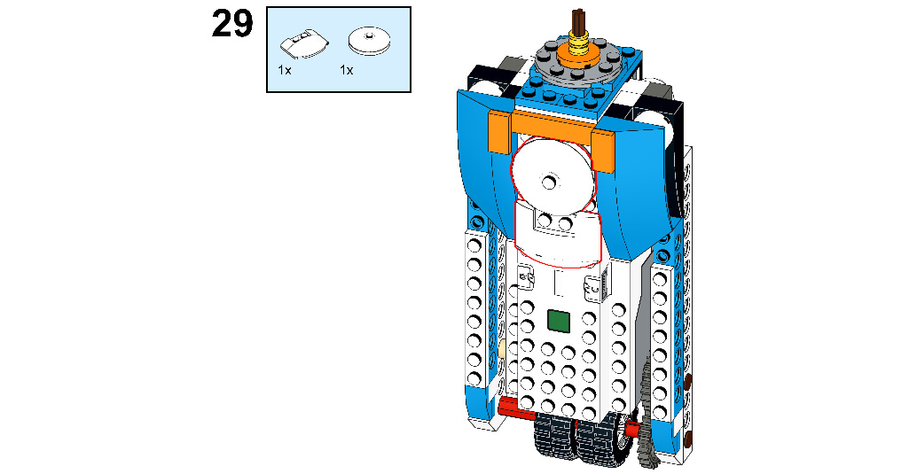
Figure 8.32
- Take three 1x2 flat tiles. Connect two flat tiles to the 1x11 plate and one flat tile to the 3x4x2 plate with a bow:
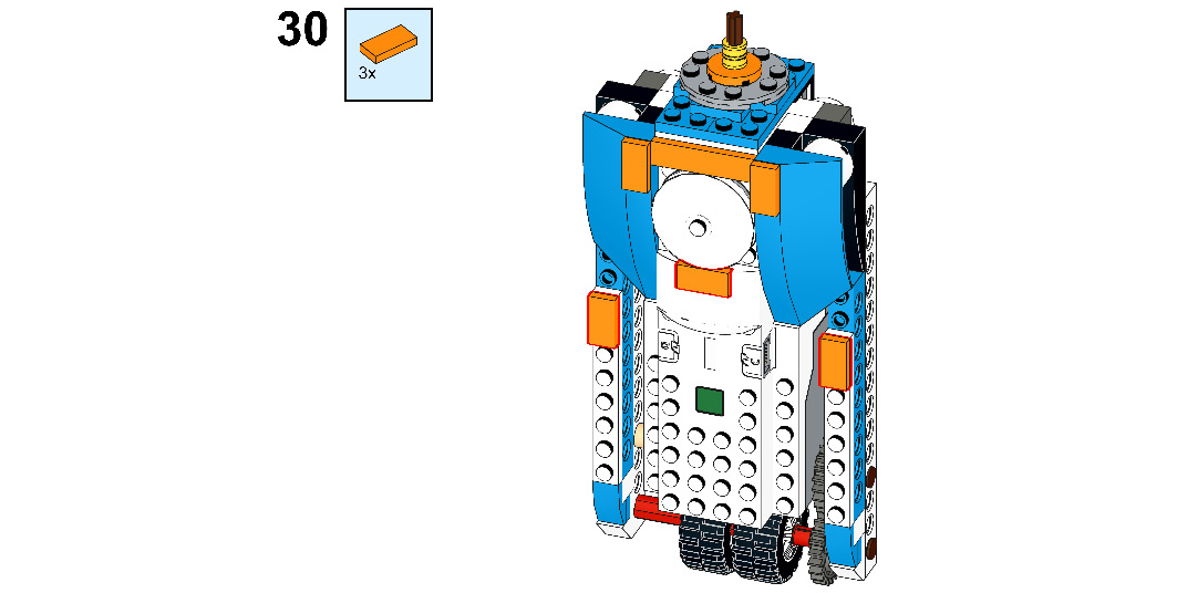
Figure 8.33
- Now, take six 2x3 plates. Connect them to the BOOST Hub as shown in the following figure:

Figure 8.34
- Now, take three 2x4 bricks with a bow and one 2x4 brick. Connect them to the 2x3 plate as shown in the following figure:
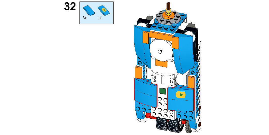
Figure 8.35
- Take two 1x2 plates. Connect them to the BOOST Hub as shown here:
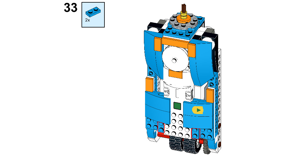
Figure 8.36
- Take four 1x2x2/3 plates with a bow. Connect them to the recently attached 1x2 plate as shown in the following figure:
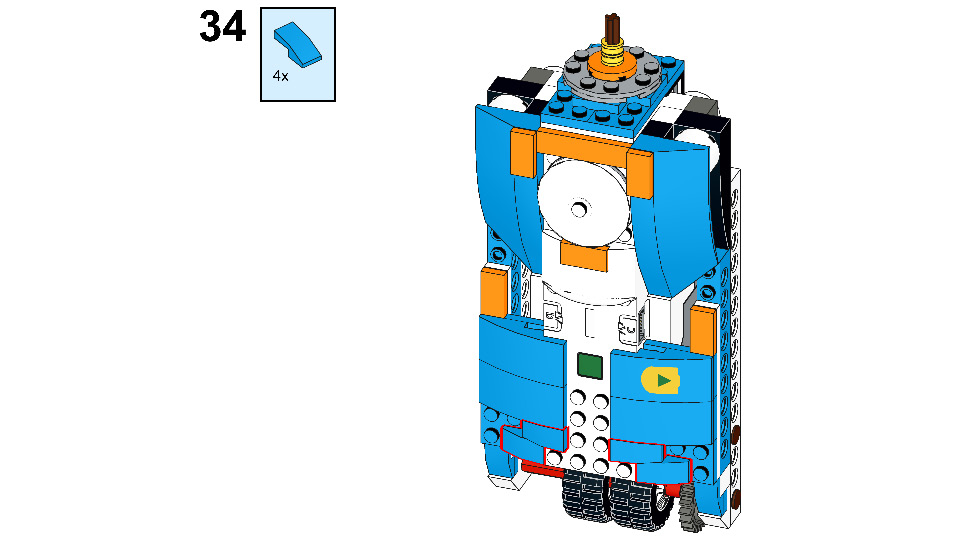
Figure 8.37
- Take two 1x2 roof tiles. Connect them to the BOOST Hub as shown in the following figure:
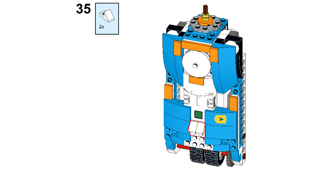
Figure 8.38
- Take one 2x2x2/3 plate with a bow. Connect it to the recently attached 1x2 roof tile and the BOOST Hub:
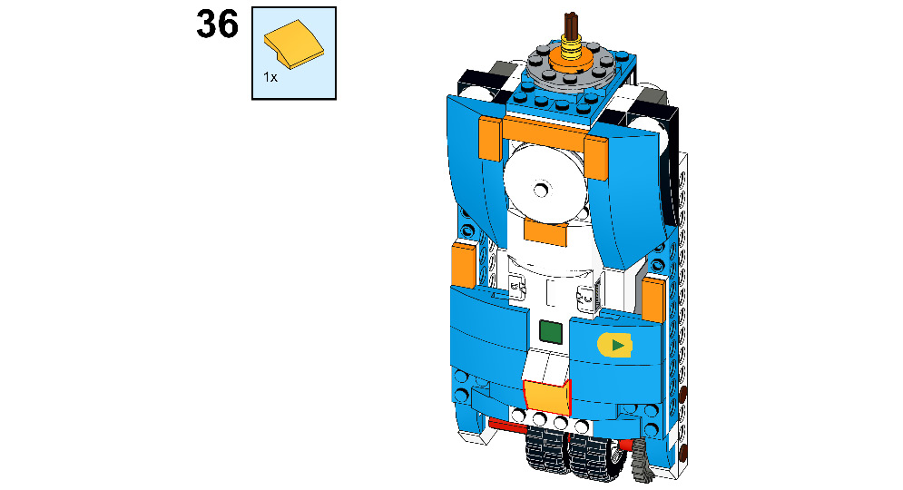
Figure 8.39
- Take one 1x2 plate. Connect it to the bottom side of the BOOST Hub:

Figure 8.40
- Take two 1x2x2/3 plates with a bow and connect them to the 1x2 plate:

Figure 8.41
- Now, take two 1x1 orange flat tiles and one 1x1 black flat tile. Connect the orange flat tile to the 2x3 plate and the black flat tile to the round plate:
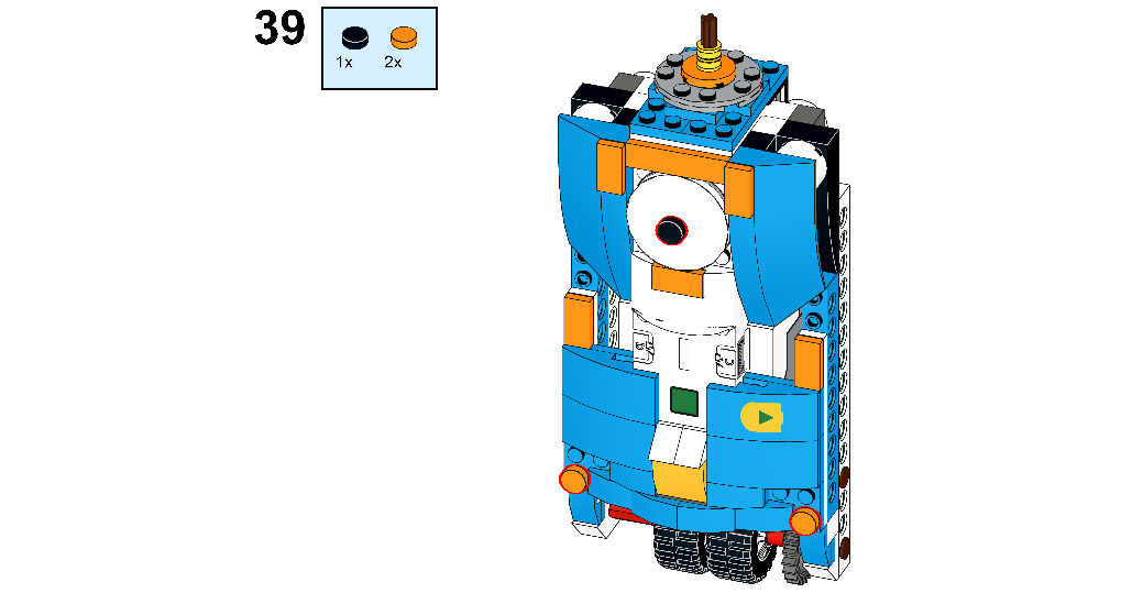
Figure 8.42
- Take four connector pegs. Connect them to the first hole and the fifth hole of the 1x16 Technic brick:
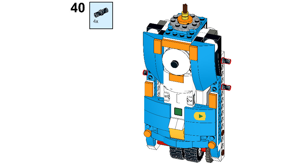
Figure 8.43
- Now, take one external motor from your BOOST kit. Flip your robot and connect this motor below the 1x2 bricks, as shown in the following figure:
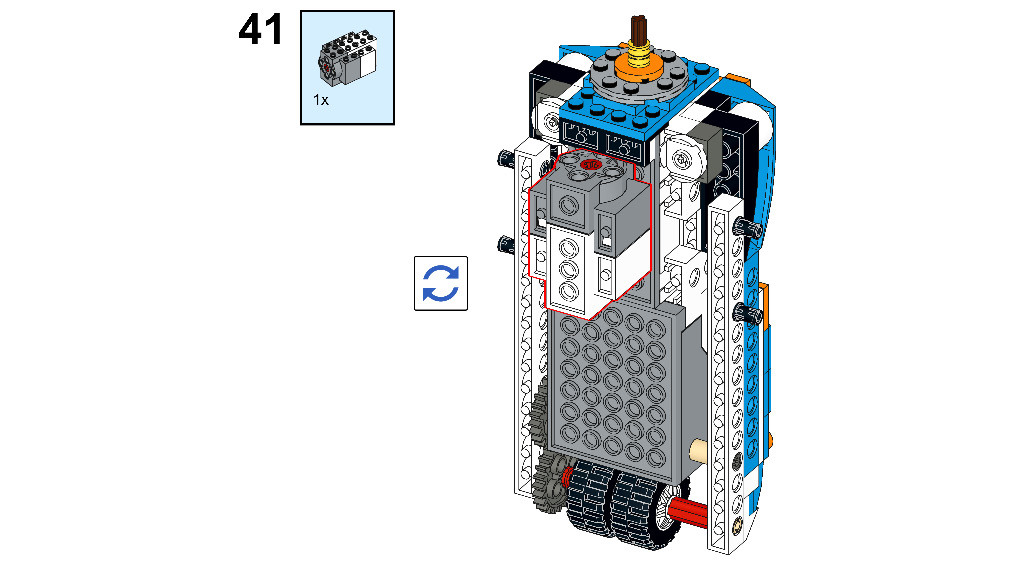
Figure 8.44
- Take two 3M connector pegs. Connect them to the external motor:
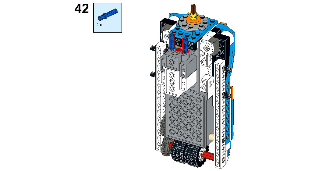
Figure 8.45
- Take two 3M Technic beams. Connect them to the recently attached 3M connector peg:
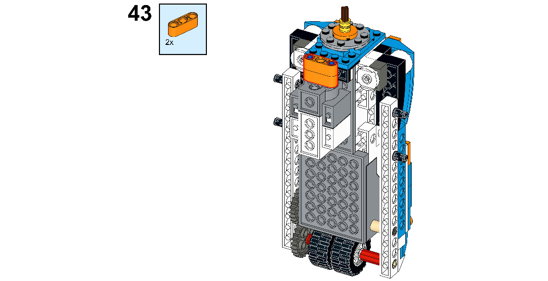
Figure 8.46
- Take two half bushings and one 4M stopper axle. Insert the half bushing on the 4M stopper axle, then connect the 4M stopper axle to the external motor through the 3M beam:
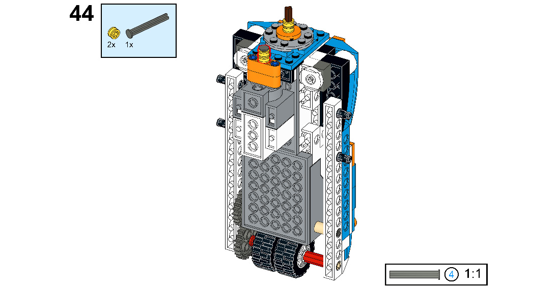
Figure 8.47
- Take one rubber band. Connect it to the half bushing as shown in the following figure:
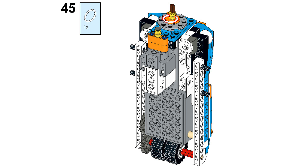
Figure 8.48
- Now, stretch the rubber band and connect it to the half bushing of the external motor:
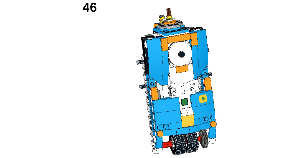
Figure 8.49
- Now, take one 2x2 round brick:
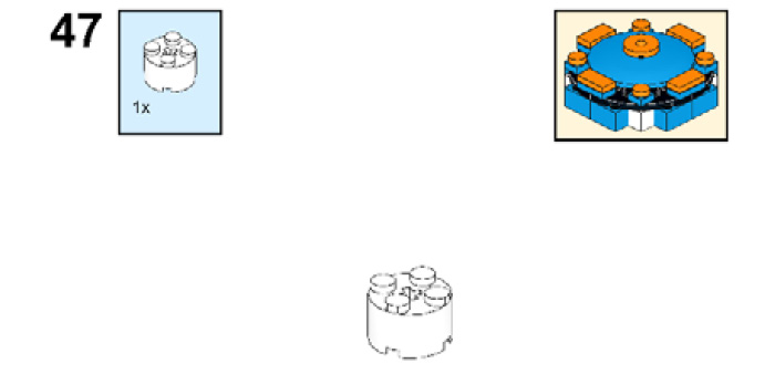
Figure 8.50
- Take four 4x4 ¼-circle plates. Arrange them as shown in the following figure:
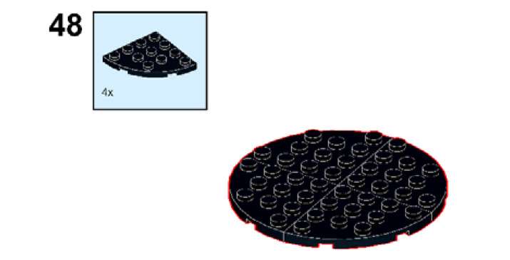
Figure 8.51
- Take one 4x6 brick. Connect it to the back side of the ¼-circle plate and connect the 2x2 round brick to the center of the ¼-circle plate:

Figure 8.52
- Take four 1x1 bricks. Connect them to the ¼-circle plate as shown in the following figure:
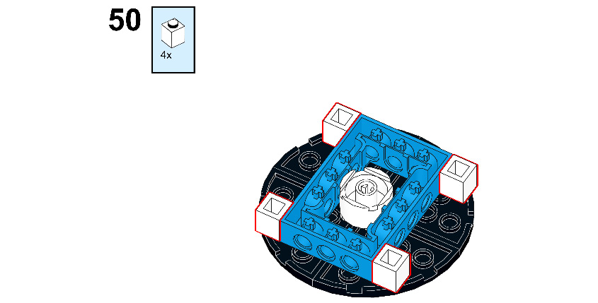
Figure 8.53
- Take four 2x2 roof tiles. Connect them to both sides of the ¼-circle plate:
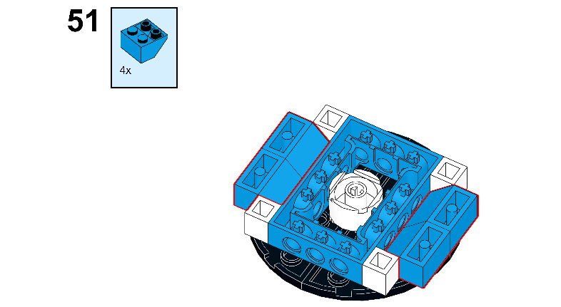
Figure 8.54
- Take four 1x2 bricks and connect them to the ¼-circle plate as shown in the following figure:
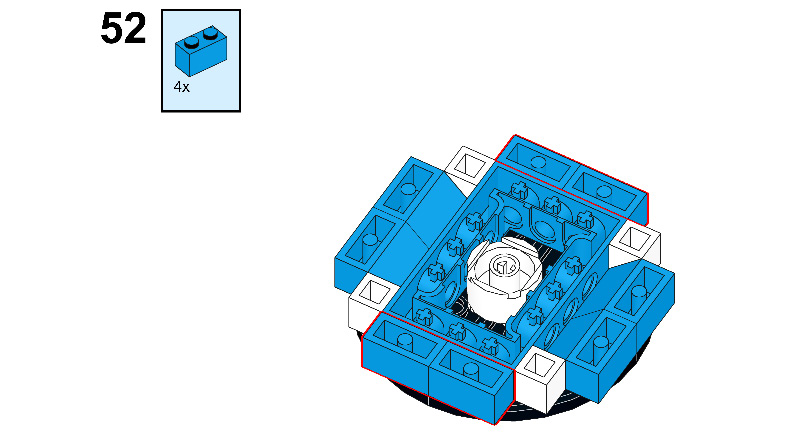
Figure 8.55
- Take one 4x4 round plate. Connect it to the top side of the ¼-circle plate:

Figure 8.56
- Take one 2x2 round plate. Connect it to the 4x4 round plate:
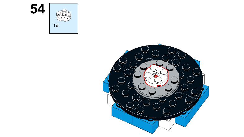
Figure 8.57
- Take one 6x6 parabola. Connect it to the 2x2 round plate as shown in the following figure:
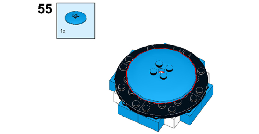
Figure 8.58
- Take one 2x2 flat round tile. Connect it to the 6x6 parabola:
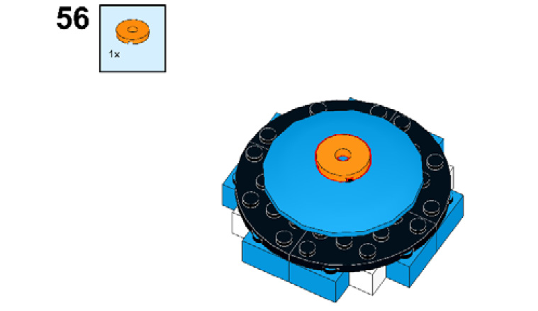
Figure 8.59
- Take four 1x2 plates. Connect them to all sides of the ¼ round plate as shown in the following figure:
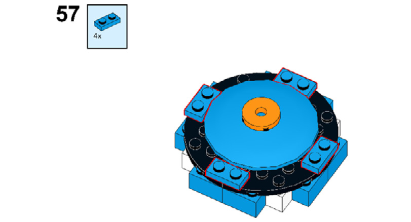
Figure 8.60
- Take four 1x1 plates. Connect them to the middle of the ¼ round plate as shown in the following figure:
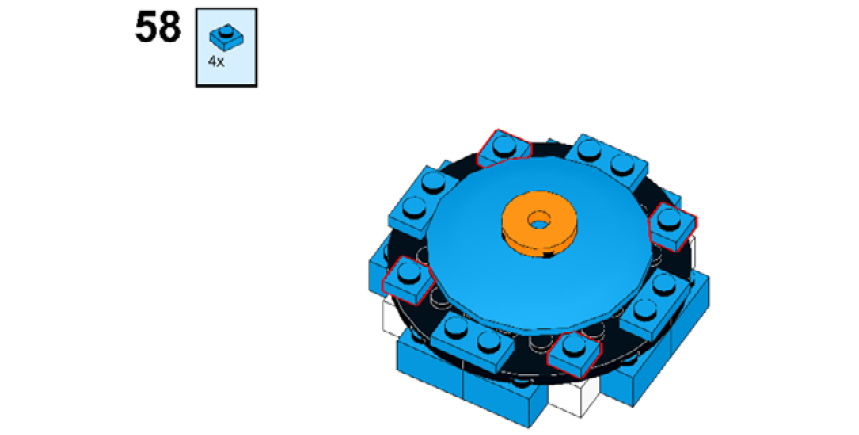
Figure 8.61
- Take four 1x2 flat tiles. Connect them to the 1x2 plate as shown here:

Figure 8.62
- Take four 1x1 flat round tiles. Connect them to the 1x1 plate:
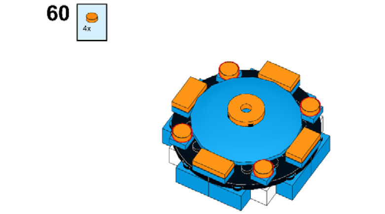
Figure 8.63
- Take the R2-D2 head and align it with the 3M axle:
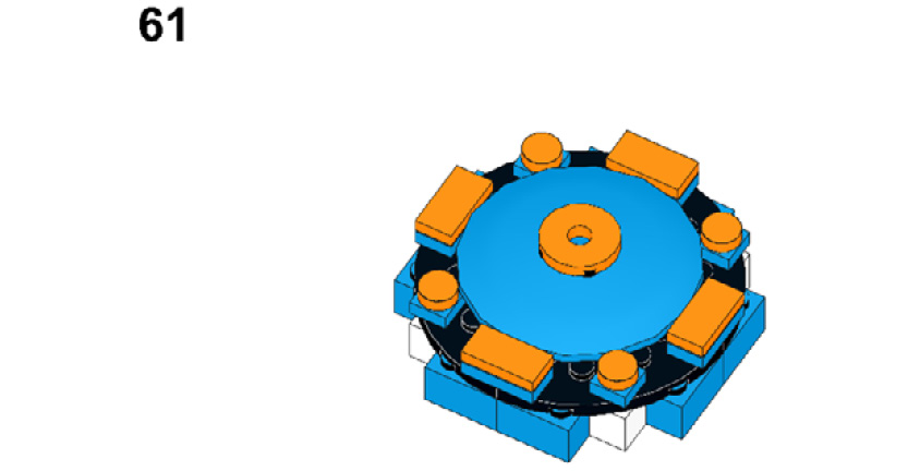
Figure 8.64
- Now, connect it to the 3M axle as shown in the following figure:
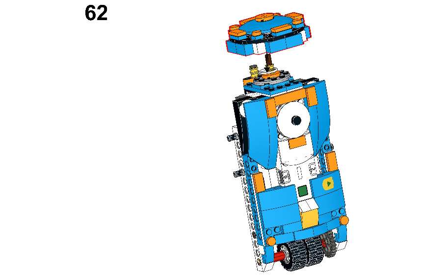
Figure 8.65
- After connecting that part, it will look as shown in the following figure:
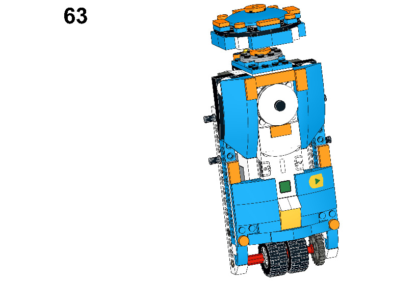
Figure 8.66
- Take one 1x16 Technic brick:
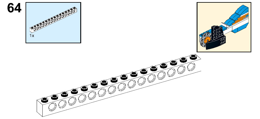
Figure 8.67
- Take one 1x6 brick. Hold the 1x6 brick beside the 1x16 Technic brick:
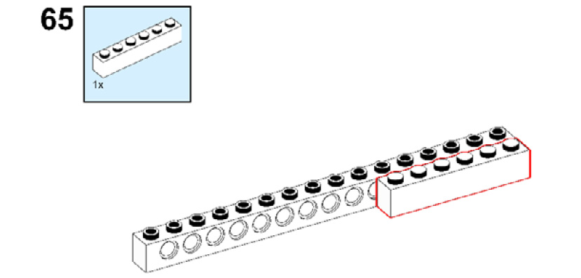
Figure 8.68
- Take two 2x2 roof tiles and one 2x2 brick with a horizontal snap. Flip the recently connected Technic bricks and connect these new pieces to them as shown in the following figure:
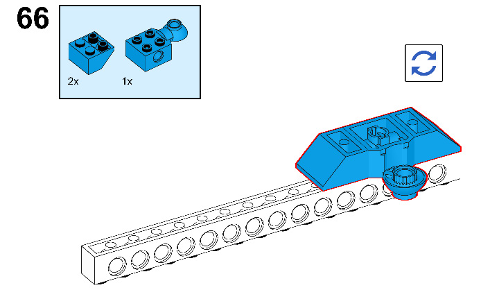
Figure 8.69
- Take one 2x11 plate with holes. Connect it to the top of the 1x16 Technic brick:
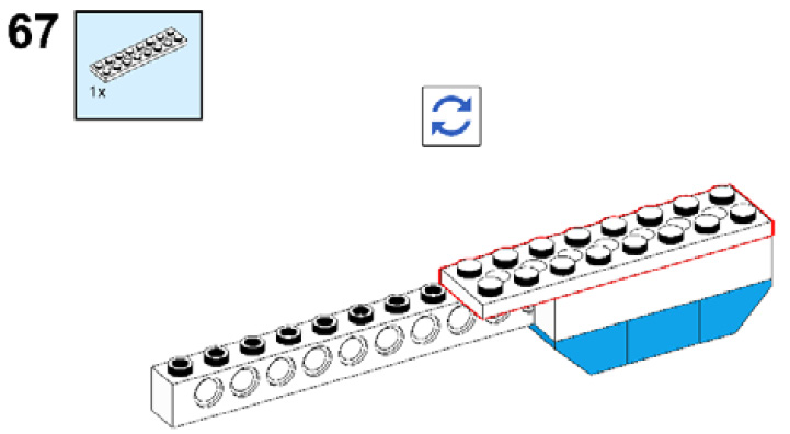
Figure 8.70
- Take one 1x4 brick and connect it below the 2x11 plate as shown in the following figure:

Figure 8.71
- Take one 2x2 plate and one 2x4 plate. Connect them to the 2x11 plate with a hole:

Figure 8.72
- Take one 1x2 plate and one 2x4 plate. Connect the 1x2 plate to the 2x2 plate and connect the 2x4 plate to the 2x4 plate and the 2x2 plate:
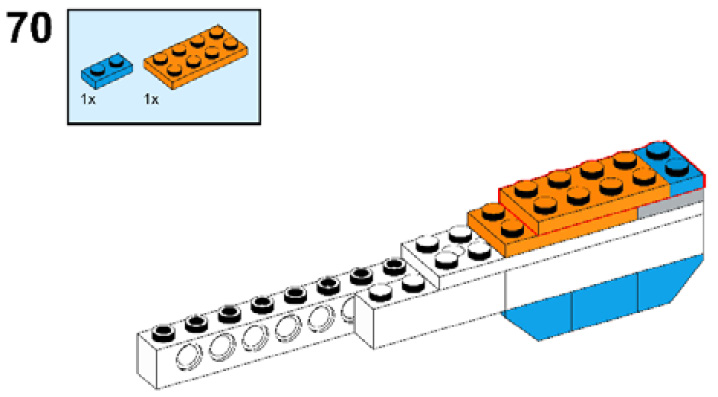
Figure 8.73
- Take one 2x4 plate and connect it to the stack of plates as shown here:
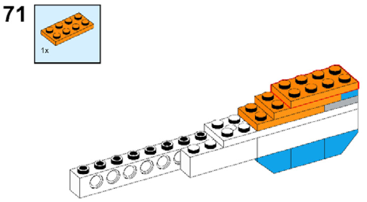
Figure 8.74
- Take one 2x3 plate and connect it to the 2x4 orange plate, then take one 1x2 plate and connect it over them:
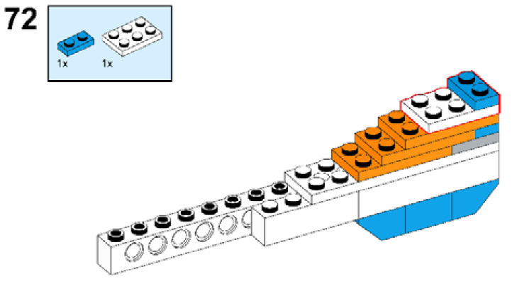
Figure 8.75
- Take two 1/3 bricks with a bow and connect them to the stack of plates as shown in the following figure:
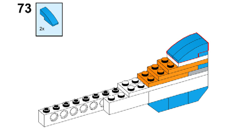
Figure 8.76
- Take two 1x2x2/3 plates with a bow and connect them as shown in the following figure:
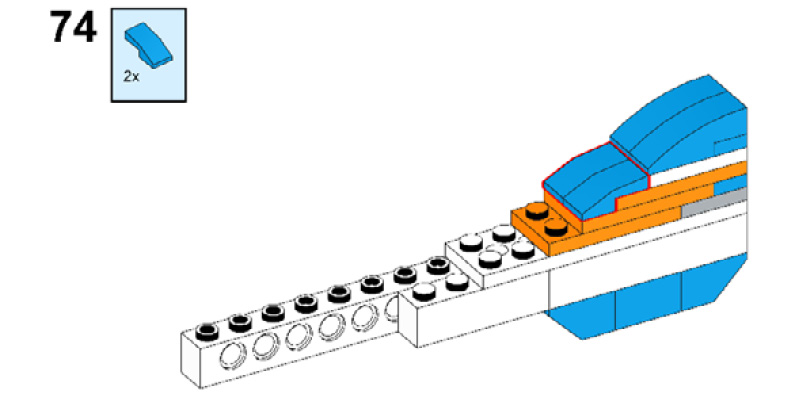
Figure 8.77
- Once again, take two 1x2x2/3 plates with a bow and connect them as shown here:
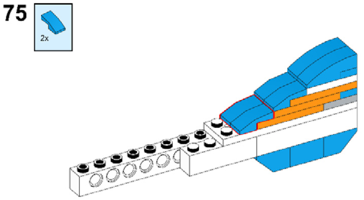
Figure 8.78
- Take one 1x2x2/3 roof tile and connect it as shown in the following figure:

Figure 8.79
- Take one 2x2 plate with a knob and connect it to the white bricks:

Figure 8.80
- Now, take one 1x4 plate and one 1x2/2x2 angle plate and connect them as shown in the following figure:
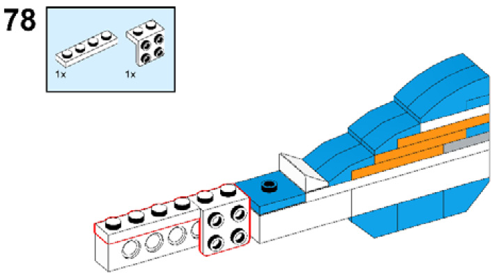
Figure 8.81
- Take one 1x2 plate and one 1x4 plate with two knobs and connect them to the arm as shown in the following figure:

Figure 8.82
- Take one connector peg and connect it to the brick as shown in the following figure:

Figure 8.83
- Take one 2x2 flat round tile with a hole and one 4x4 round plate with a snap and connect them as shown in the following figure:
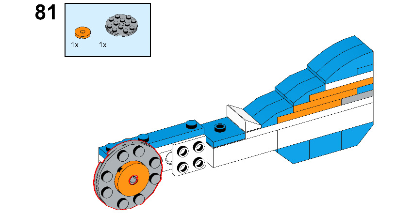
Figure 8.84
- Take one 2x4 brick and connect it to the 1x2/2x2 angle plate:
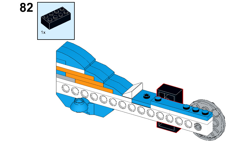
Figure 8.85
- Take one 2x6 brick with a bow and one ¼ circle of the 4x4 plate and connect them to the 2x4 brick:
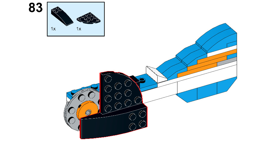
Figure 8.86
- Now connect this arm to the body of R2-D2, as shown in the following figure:
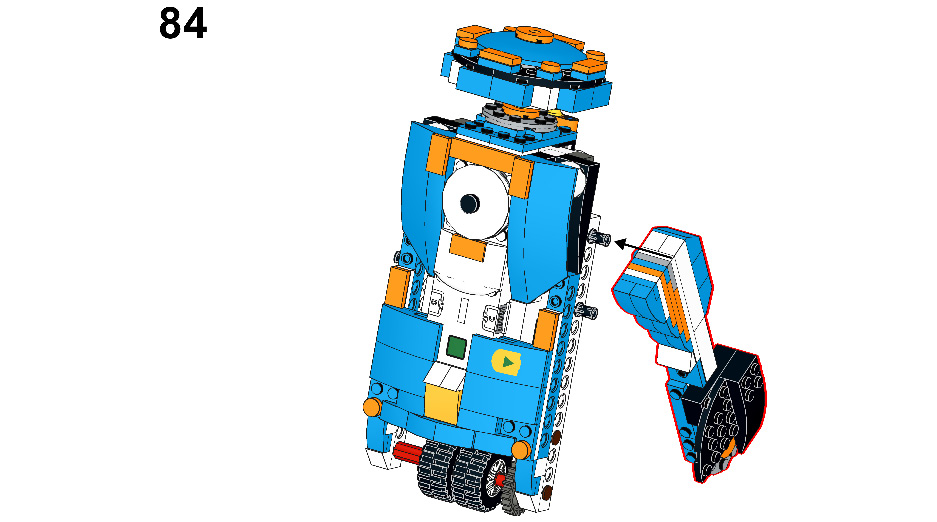
Figure 8.87
- Check that the connection is correct by comparing it with the following figure:
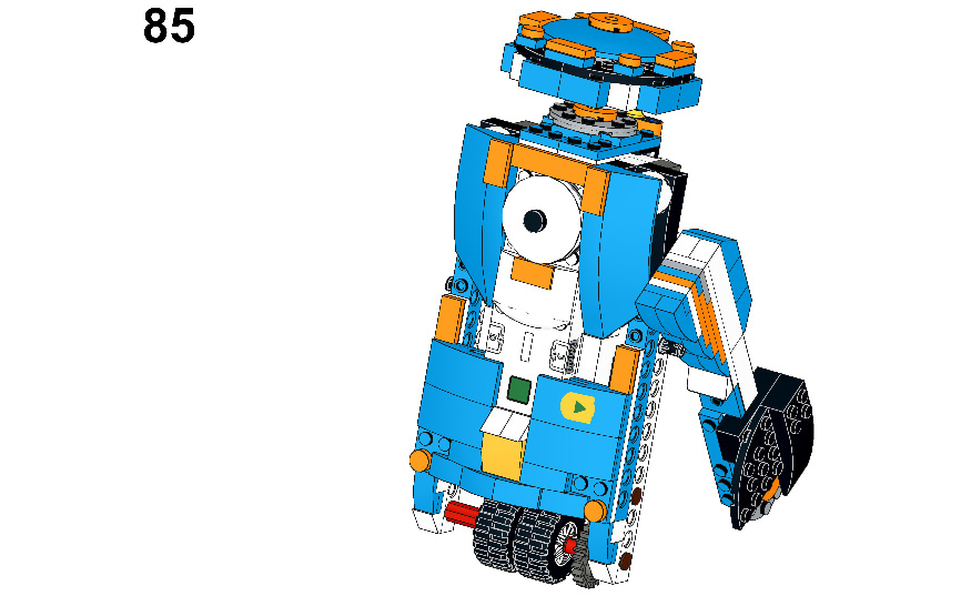
Figure 8.88
- Now, we are going to make the other arm for our R2-D2. Let's start by taking one 1x16 Technic beam:

Figure 8.89
- Take one 1x6 brick and put it beside the 1x16 brick:
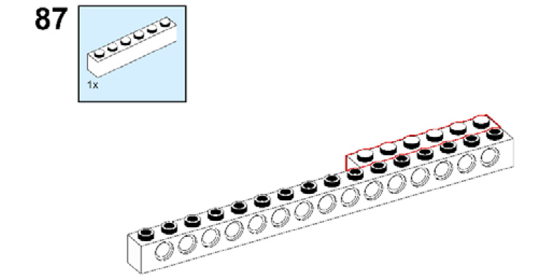
Figure 8.90
- Take one 2x2 brick with a horizontal snap and connect it to the back side of both bricks as shown. Then, take two 2x2/45 inverted roof tiles and connect them to both sides of the 2x2 brick with a horizontal snap:
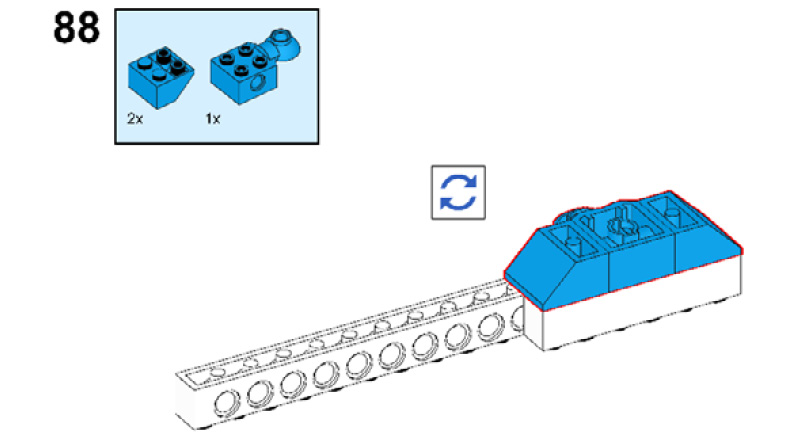
Figure 8.91
- Take one 1x4 brick and put it in place as shown:
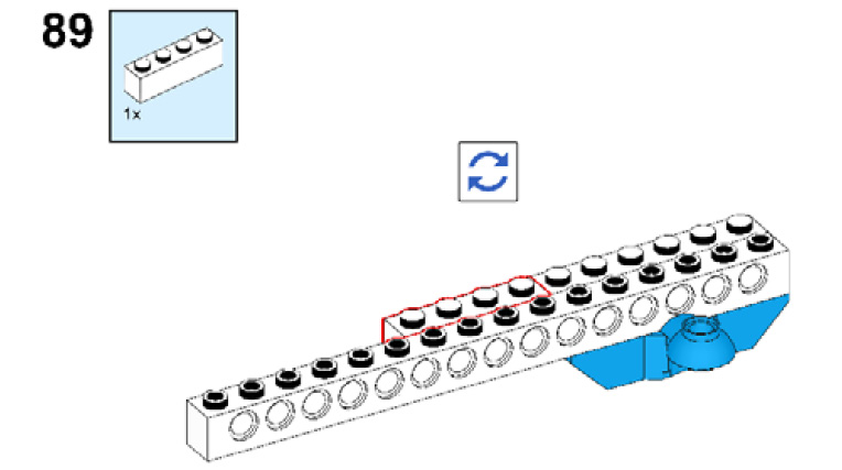
Figure 8.92
- Take one 2x11 plate. Connect the 1x16 brick to the 1x6 and 1x4 bricks using this plate as shown in the following figure:

Figure 8.93
- Take one 2x2 plate and one 2x4 plate and attach them to the 1x11 plate:

Figure 8.94
- Now, take one 1x2 plate and connect it to the 2x2 plate and take one 2x4 plate and connect it to both the 2x2 and 2x4 plates, as shown in the following figure:
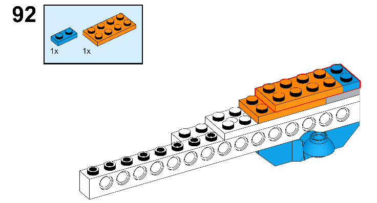
Figure 8.95
- Take one 2x4 plate and connect it to the stack of plates:

Figure 8.96
- Take one 2x3 plate and connect it to the stack of plates:
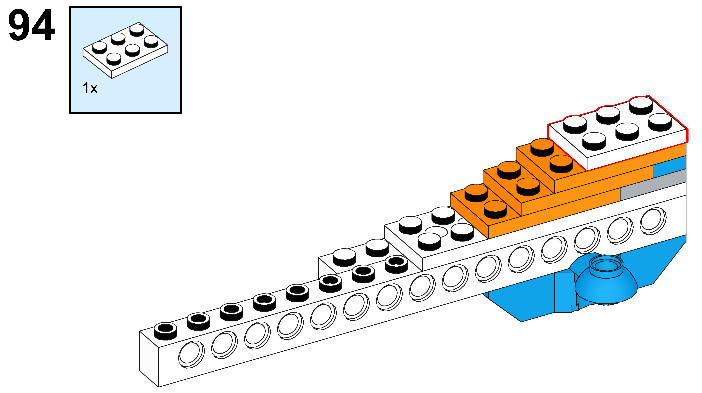
Figure 8.97
- Take one 1x2 plate and connect it as shown:
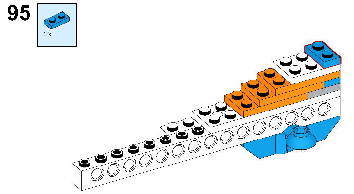
Figure 8.98
- Take two 1/3 bricks with a bow and connect them to the stack of plates as shown in the following figure:

Figure 8.99
- Take two 1x2x2/3 plates with a bow and connect them as shown in the following figure:
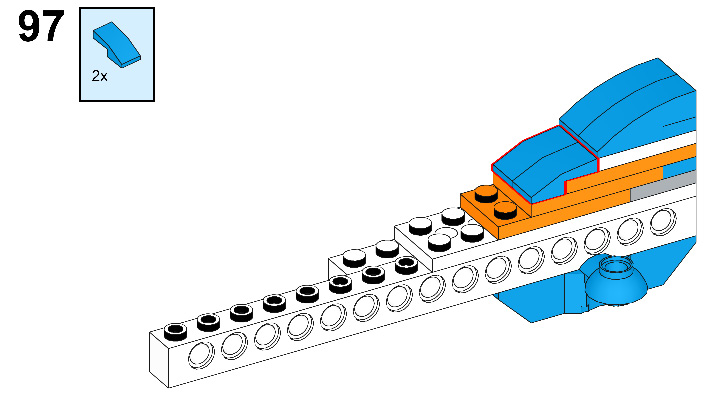
Figure 8.100
- Once again, take two 1x2x2/3 plates with a bow and connect them as shown here:
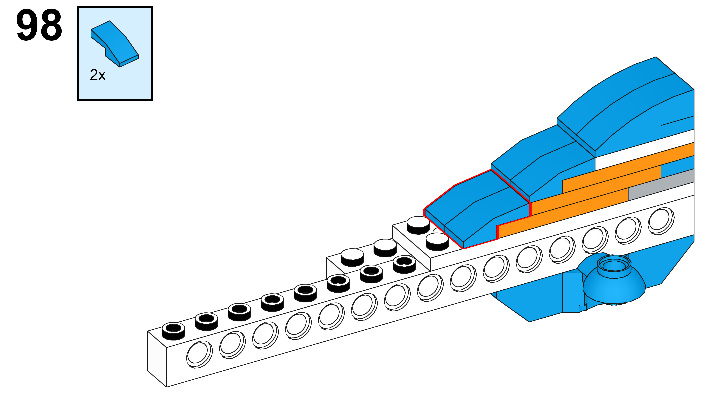
Figure 8.101
- Take one 1x2x2/3 roof tile and connect it as shown in the following figure:
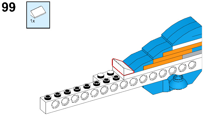
Figure 8.102
- Take one 2x2 plate with a knob and connect it to the white bricks:
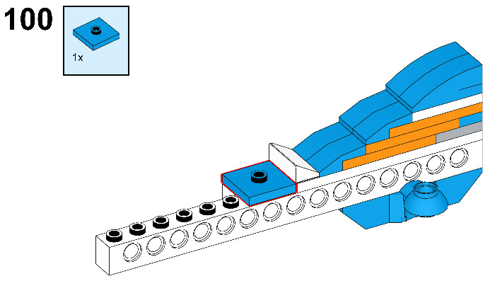
Figure 8.103
- Now take one 1x4 plate and one 1x2/2x2 angle plate and connect them as shown in the following figure:
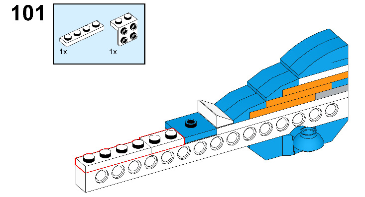
Figure 8.104
- Take one 1x4 plate with two knobs and connect it to the arm as shown in the following figure:

Figure 8.105
- Take one connector peg and connect it to the brick as shown in the following figure:
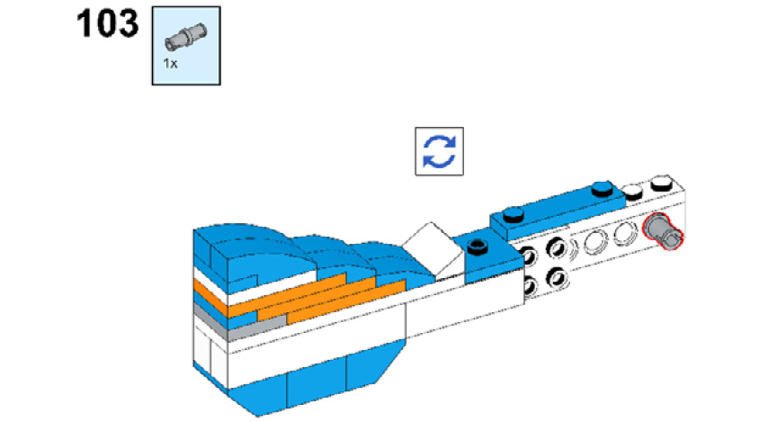
Figure 8.106
- Take one 2x2 flat round tile with a hole and one 4x4 round plate with a snap and connect them as shown in the following figure:
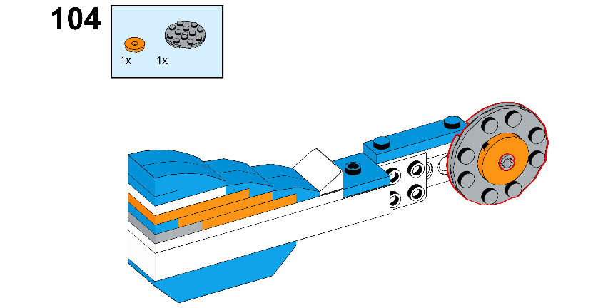
Figure 8.107
- Take one 1x2 plate and connect it to the arm as shown in the following figure:
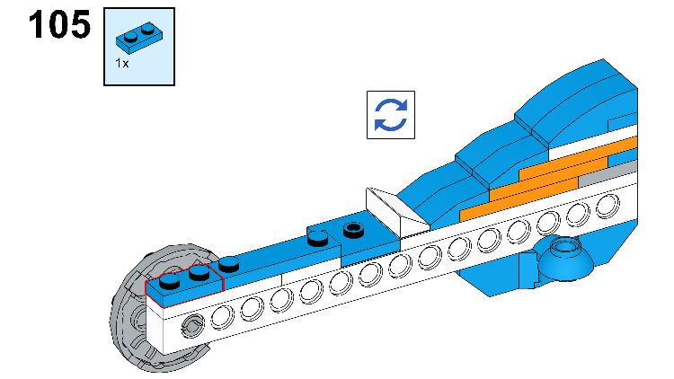
Figure 8.108
- Take one 2X4 brick and connect it to the 1x2/2x2 angle plate:
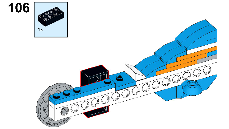
Figure 8.109
- Take one 2x6 brick with a bow and one ¼ circle of the 4x4 plate and connect them to the 2x4 brick:
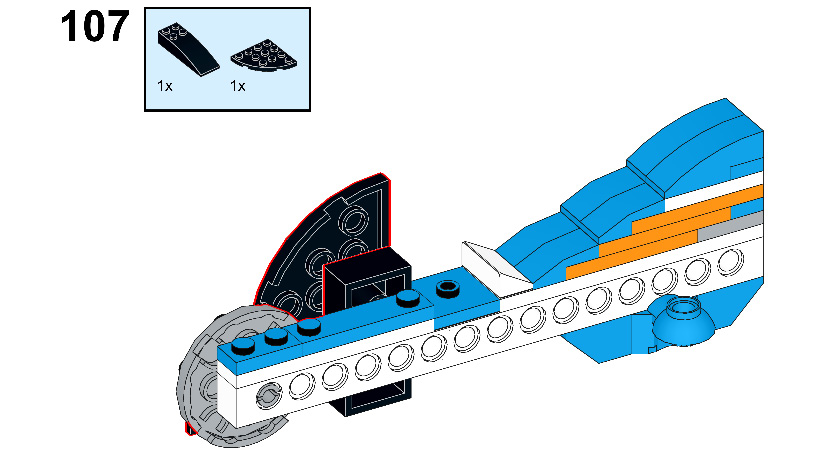
Figure 8.110
- Compare your model to the model shown in the following figure:

Figure 8.111
- Now connect this arm to the other side of the body of R2-D2 as shown:

Figure 8.112
- Check that the connection is correct by comparing it to the following figure:
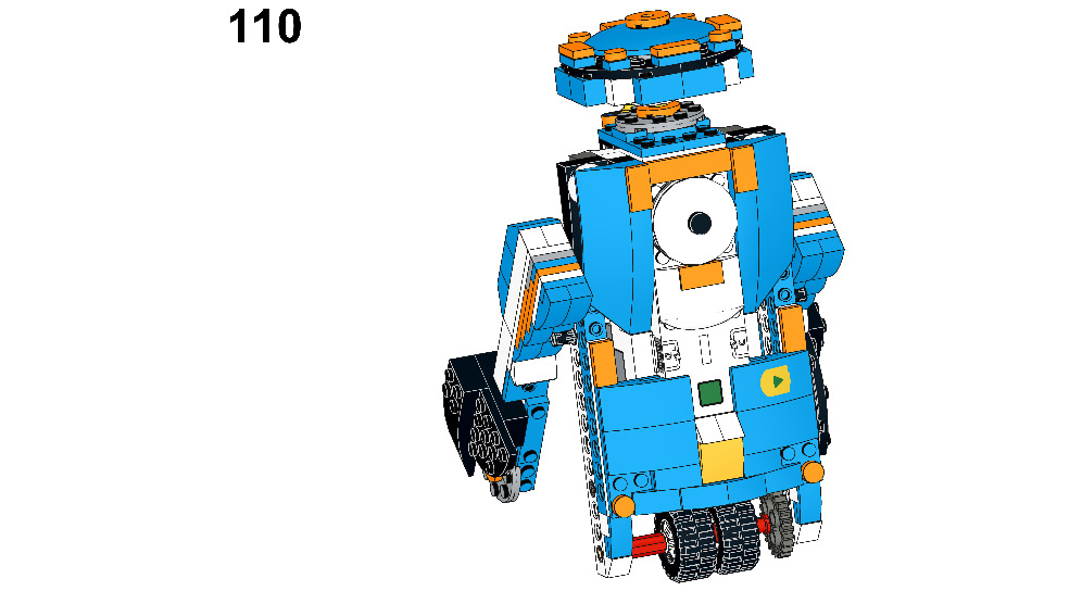
Figure 8.113
- Take one 2x12 plate and connect it to the back side of the model to support the arms:
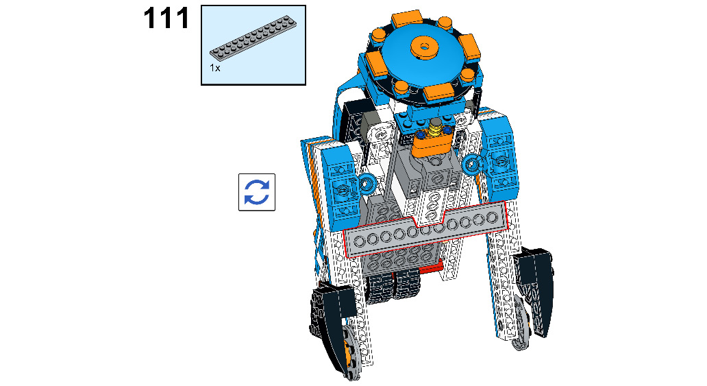
Figure 8.114
- Once again, take one 2x12 plate and connect it below the first one:
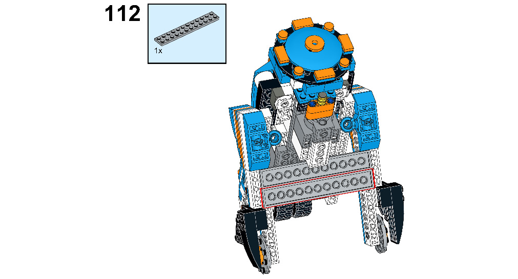
Figure 8.115
And there you go! Your R2-D2 lookalike robot using the BOOST kit is ready:

Figure 8.116
Let's perform some fun tasks using this R2-D2 robot. Since the drive wheels of this robot are connected to a single motor, it will not be able to make turns.
Let's code the robot to move on a specific path
In this activity, you will be making use of sound and display blocks to make the R2-D2 more interactive.
Activity
Do the setup as shown in Figure 8.117. R2-D2 is on a rescue mission for his master – Padme. R2-D2 needs to reach the computer system in under 5 seconds and turn it off by moving his head 180 degrees after reaching the spot. Once done, display Padme Saved! Mission Successful and play Hooray:
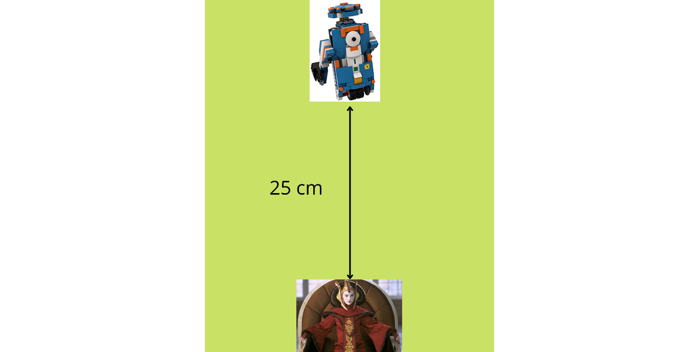
Figure 8.117 – Route setting
The sample code for this activity is given here:

Figure 8.118 - Sample code
Now, let's move on to a challenge.
Time for a challenge
Build a small LEGO element that can represent Yoda. You will have to attach this element to your R2-D2 robot. You can build it using spare LEGO elements from your BOOST kit/use any of your LEGO minifigures that you have at home. Once done, program your R2-D2 to do the following:
- Go and meet Jedi Master Yoda at point A. Rotate R2-D2's head one time when the task is done and change the BOOST Hub light color to purple.
- Reorient the position of R2-D2 toward Dagobah, the mysterious force planet. Now, reach this planet in less than 6 seconds with Yoda. Rotate the neck for one full rotation and display the message Landed successfully on Dagobah with the master. Also play a unique sound for 3 seconds.
- Now, reorient R2-D2 toward the base position again and program it to reach the base in under 4 seconds.
- Calculate the total time taken to perform this activity once you are set with the route. Time taken = __________ seconds.
Your route setting will look as shown in the following figure:
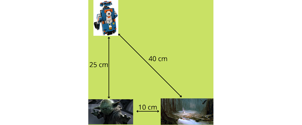
Figure 8.119 – Route for the challenge
You can try creating different routes and solving different missions for R2-D2 for your own coding practice. You will have to orient the robot in the direction you need to solve the mission since this R2-D2 is not capable of making turns. You can even consider making modifications to this construction and drive both wheels with different motors.
Summary
In this chapter, you built an R2-D2 robot using the application of gears as well as a simple machine pulley. You solved two tasks: one to rescue Padme and another to pick up the Jedi Master and go to the planet Dagobah. The purpose of this chapter was to strengthen your construction skills using the pieces given in your LEGO BOOST kit. By now, you should be able to build robots that have human-like movements, such as the neck movement of R2-D2. You should also be able to design robots that are like real-life/sci-fi character robots that you have seen either onscreen or in real life. In the next chapter, you will be building an automated entrance door with the help of a color sensor. The door construction will resemble the entrance that you see at malls/offices where the door will open only for specific people and not for others. It will be a fun task for you.
Further reading
- You can learn more about the features and importance of R2-D2 at https://www.starwars.com/databank/r2-d2.
- To learn more about pulleys, visit https://www.flight-mechanic.com/simple-machines-the-pulley/.