
Chapter 4: LEGO BOOST Rover
Anything that reduces human effort is called a machine. A simple machine is a mechanical device for applying force. Any complex machine is a combination of two or more simple machines. We will learn how to apply a few of these simple machines in our upcoming projects. In science, there are a total of six simple machines, as follows:
- Wheel and axle
- Pulley
- Lever
- Wedge
- Screw
- Inclined plane
Wheels and axles help move heavy loads from one place to another by reducing the friction between the load and the surface, owing to its round shape. The wheel is considered one of the greatest discoveries of mankind. You can find numerous examples in and around your vicinity where wheels are used extensively to make things move easily, for example, your holiday suitcase! Have you ever tried picking up your suitcase when it is completely full? It is extremely heavy and almost impossible to lift, right? And what does your suitcase have? It has four small wheels at the bottom that makes moving such a heavily loaded suitcase extremely easy and fun. You can find many such applications of wheels and axles in your day-to-day life. Can you think of at least three places where you have seen this application of wheels and axles?
- _______________________________________________
- _______________________________________________
- _______________________________________________
Great! In this chapter, you will make use of wheels and axles to help the robot move freely on the floor. You will also learn about two different types of turns that a robot can perform and execute those turns in the respective activities. Exciting, isn't it?
In this chapter, we will cover the following topics:
- Building the BOOST rover
- Making the rover move
- Time for a challenge
Technical requirements
In this chapter, you will need the following:
- A LEGO BOOST kit with six AAA batteries, fully charged
- A laptop/desktop with Scratch 3.0 installed on it and an active internet connection
- An A3 size drawing sheet with a pencil and ruler
Building the BOOST rover
In this section we will build the robot as shown in the following figure:
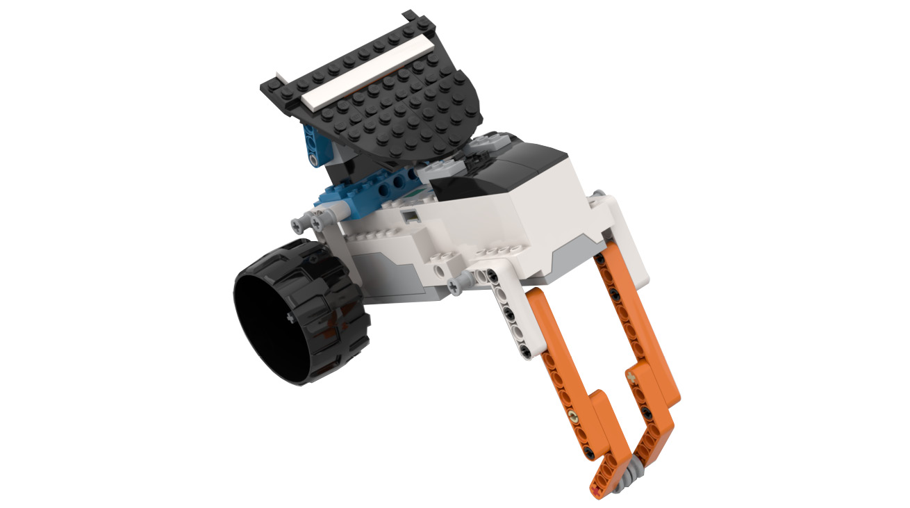
Figure 4.1
Follow the given steps to build the robot:
- Make sure you insert six AAA working batteries into your BOOST Hub before you start the construction process:

Figure 4.2
- Now, take two 2x6 bricks with bows. Attach them to the BOOST Hub:
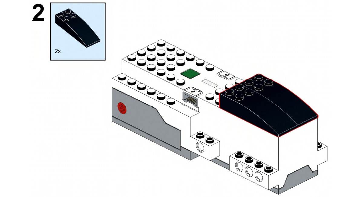
Figure 4.3
- Now, take two 1x2 plates with ball cups. Connect them to the 2x6 bricks with bows:
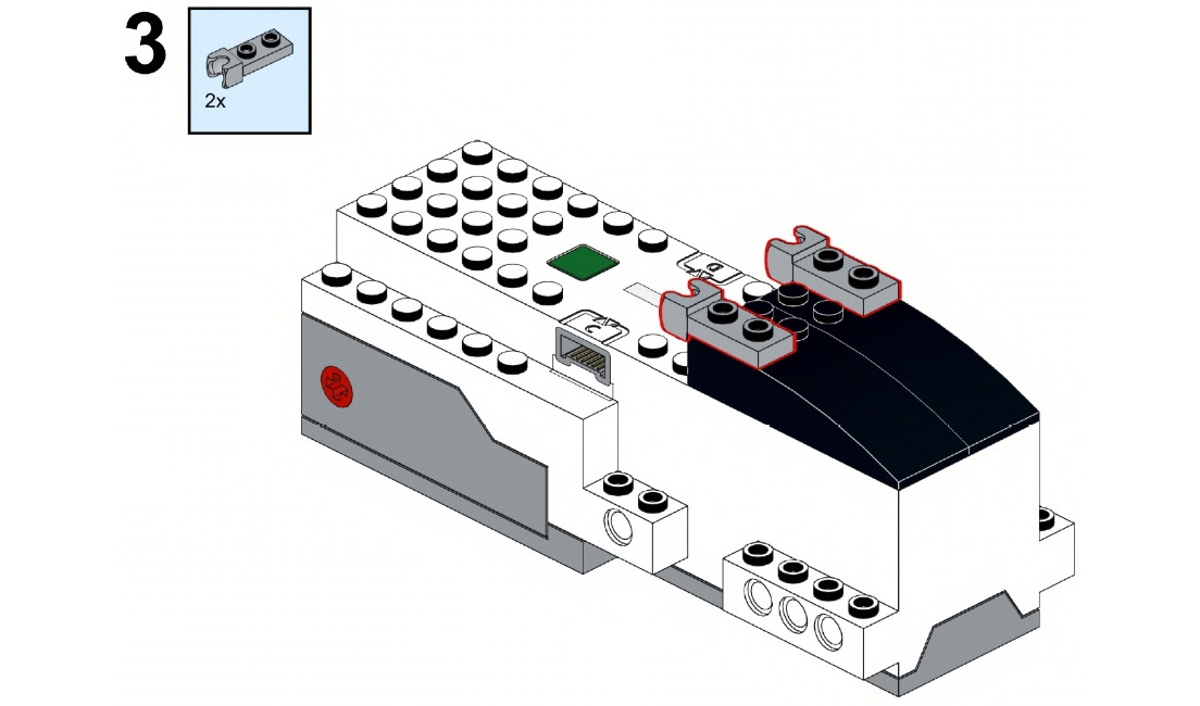
Figure 4.4
- Take a 4x6 brick and connect it to the BOOST Hub, as shown here:
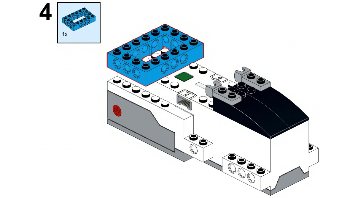
Figure 4.5
- Take a 2x4 brick, a 2x6 plate, and a 2x4 bearing element with a snap. Attach the 2x6 plate first and then attach the 2x4 brick to it. Now, connect this 2x4 bearing element with a snap on the top of it:
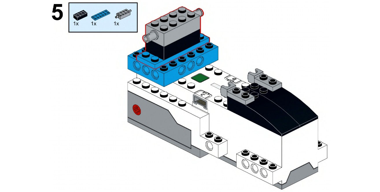
Figure 4.6
- Take two 5.5M axles with 1M stops and connect them to both motor A and motor B of the BOOST Hub:
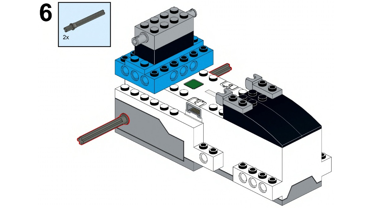
Figure 4.7
- Now, take two 3x5 angular beams and connect them to the axle on both sides:

Figure 4.8
- Take four 2M friction snaps with cross holes. Connect them to the 3x5 angular beam on both sides via the first and third holes:
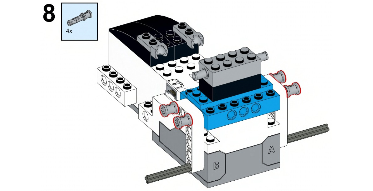
Figure 4.9
- Now, take two 2x2 round bricks with crosses and two 2x2 flat round tiles with a hole in it. Connect them to the axles on both sides. Ensure that the studs of the round bricks with crosses are attached firmly to the flat round tiles:
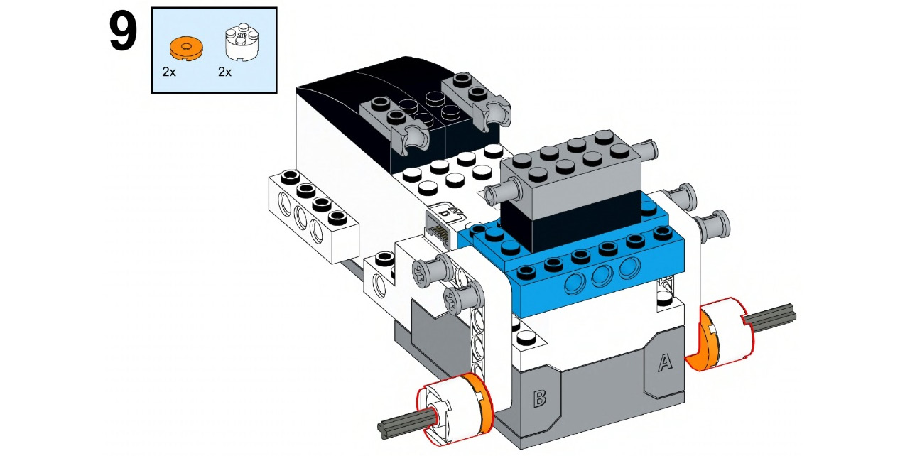
Figure 4.10
- Now, take two wheels and connect them to the axle with the connection that you just made. This wheel must slip over the round brick and plate:
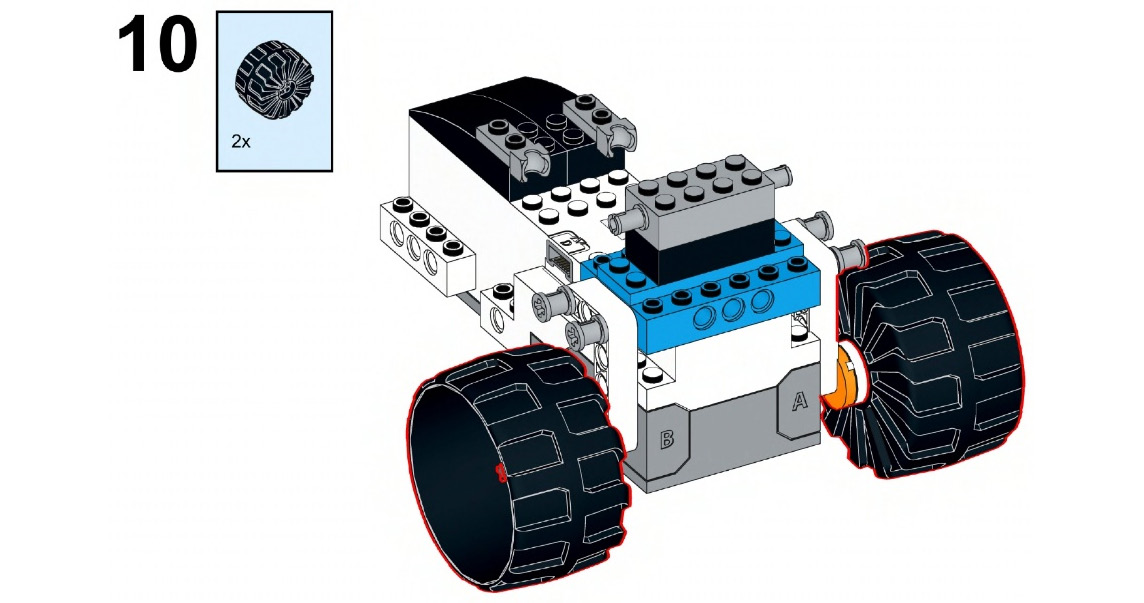
Figure 4.11
- Now, connect two black pegs to both sides of the BOOST Hub:
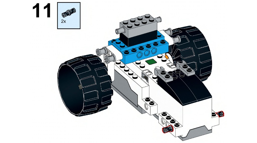
Figure 4.12
- Now take two 3x5 angular beams and connect them to the pegs that you just attached to the hub. Here, we are building the driven wheel:
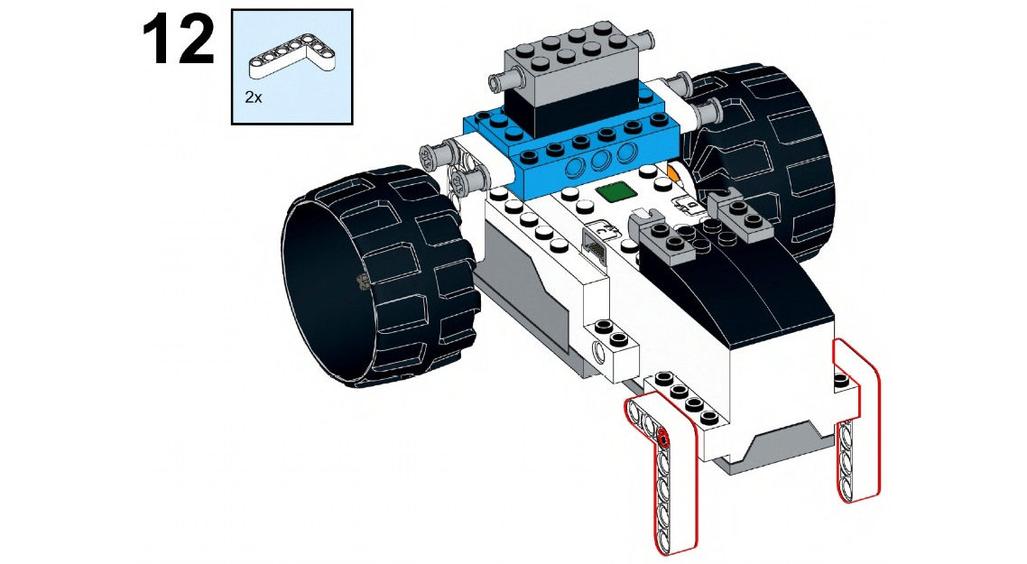
Figure 4.13
- Take two friction snaps with crosses and connect them to the 3x5 angular beam:

Figure 4.14
- Take four black pegs and connect them to the 3x5 angular beam from the inside:
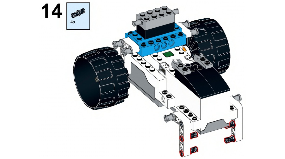
Figure 4.15
- Take two 9M beams and connect them to the recently attached pegs on the angular beams on both sides of the robot:
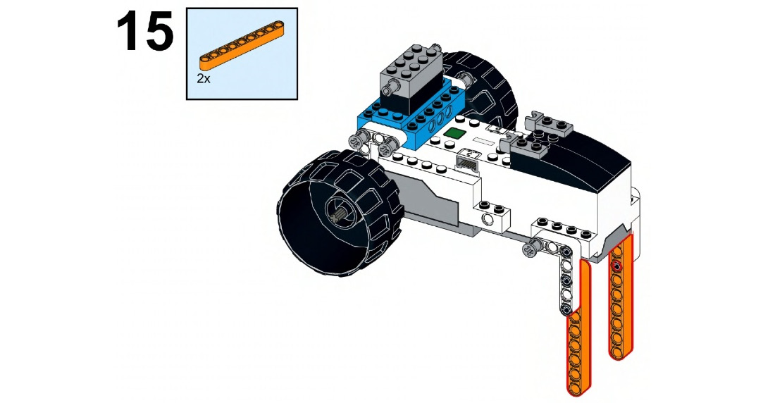
Figure 4.16
- Take two black pegs and two connector pegs with cross axles. Attach them to the 9M beams via the holes shown in the following figure:
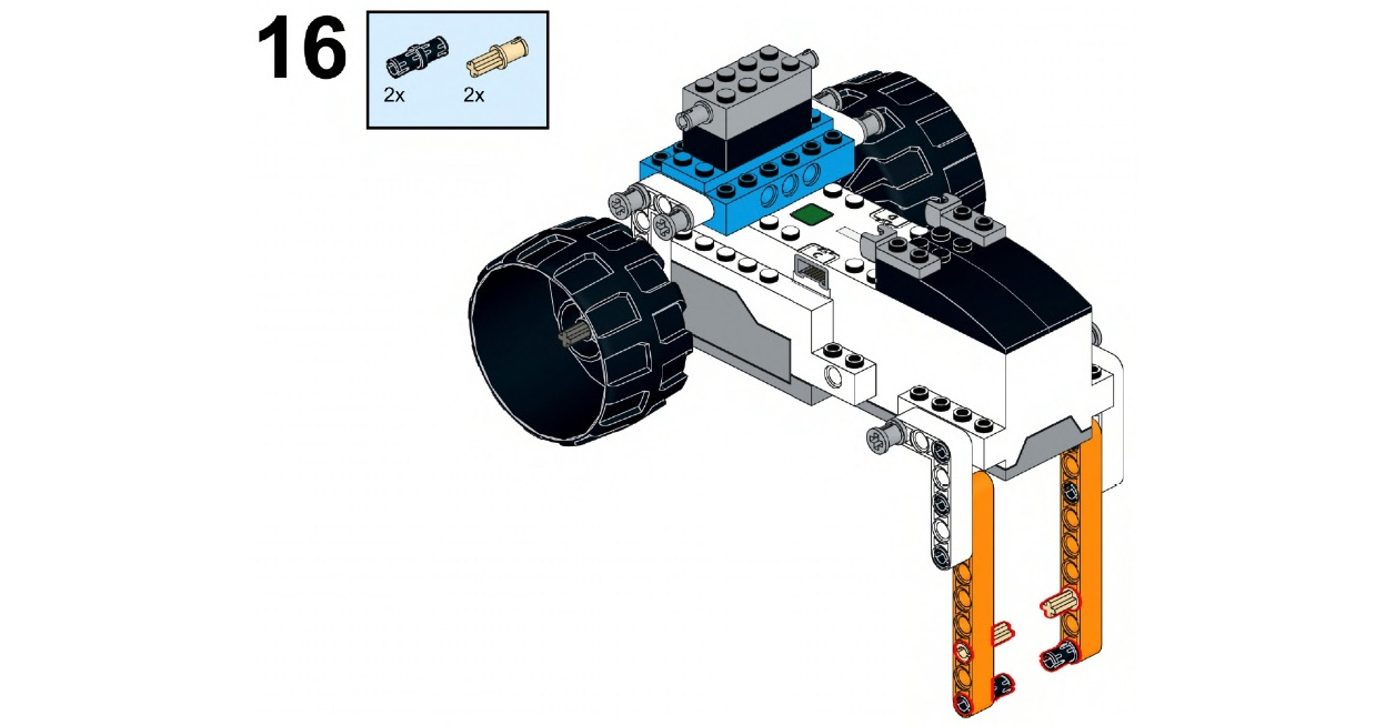
Figure 4.17
- Take two 4x4 angular beams and connect them to the 9M axles, as shown here. Make sure that the cross holes of the 4x4 angular beams are connected to the connector pegs of the cross axles:
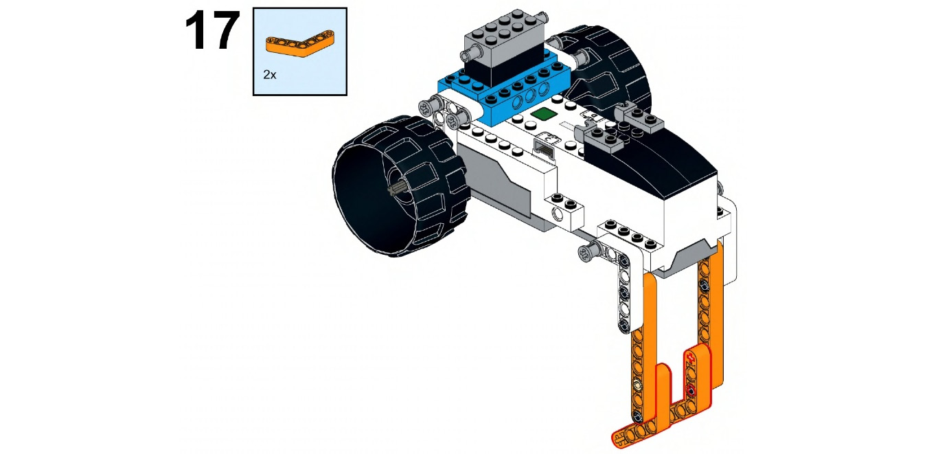
Figure 4.18
- Take two hub wheels and a 4M cross axle. Connect them to the angular beam by its last cross hole. This connection will serve as your driven wheel:

Figure 4.19
- Take two 5M beams and connect them to the 2x4 brick with snaps:

Figure 4.20
- Now, take two 1x2 bricks with snaps and connect them to the other ends of the 5M beams that you just attached:
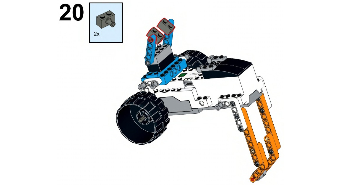
Figure 4.21
- Take a 1x4 plate and a 2x4 plate. Connect them to the 1x2 bricks with snaps, as shown in the following figure:

Figure 4.22
- Take two 4x4 plates that are 1/4 circles. Connect them to the underside of the 2x4 plate that you attached in the previous step:

Figure 4.23
- Take a left 3x8 angle plate and a right 3x8 angle plate and connect them to the recently connected LEGO bricks:

Figure 4.24
- Take two 1x8 flat tiles and use them to connect the left and right 3x8 angle plates, along with the other LEGO bricks. Then, take a 1x10 brick and connect it so that it is in between the two flat tiles. This will make this connection stable:
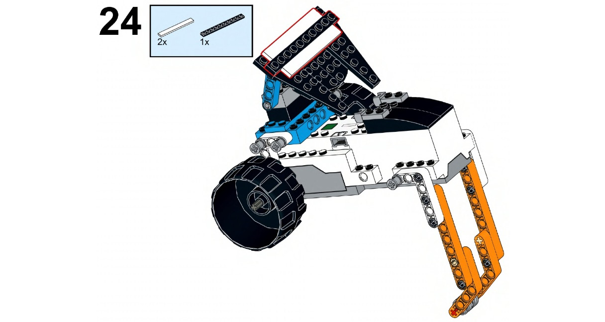
Figure 4.25
- Take a 4x4 LEGO plate and place it on top of the 1/4 circle plates:

Figure 4.26
- Take two 1x2 plates with ball ends. Connect them with the already attached 1x2 plates with ball cups from one end and on the 3x8 plates with angle on the other end. Now, take two 4x4 plates with arc and connect them as shown in the following figure:
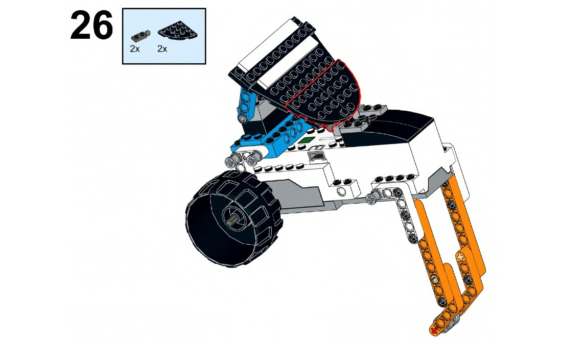
Figure 4.27
The robot that you have built here uses the two internal motors of your BOOST Hub to power two wheels individually. Your turning becomes possible and easy when your drive wheels are powered individually. Remember one thing – the speed difference between your two drive wheels makes turning possible.
Making the rover move
First, let's learn how to make our robot move straight by powering both motors at the same time. We will be using the same programming blocks that we used in Chapter 2, Building Your First BOOST Robot – Tabletop Fan, and Chapter 3, Moving Forward/Backward Without Wheels, but we will be selecting the AB option from the drop-down menu, as shown in the following screenshot. Here, I have written a program to make the robot go forward for two rotations at 100% speed:
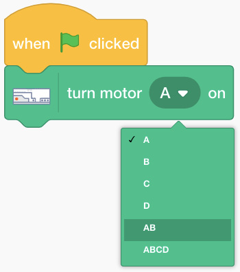
Figure 4.28 – Selecting "AB" from the drop-down menu
Now that you know how to power both motors at the same time, let's write the main code:
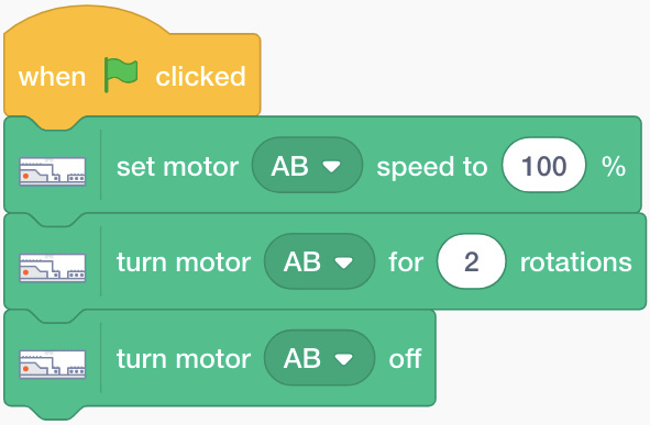
Figure 4.29 – Sample program for forward programming
Now, let's perform a few activities.
Activity 1
Can you program your robot to do the following?
- Move forward for 2 seconds at 60% speed.
- Wait for 2 seconds and change the BOOST Hub light's color to purple.
- Move backward for three rotations at 30% speed.
Great! Now, let's learn how to code our robot to follow an L shape. For this, we need to understand how to turn the robot. There are two different types of turns:
- Point turn: In this turn, one wheel moves forward while the other wheel moves backward at the same speed. When you perform this action, your robot turns on its own point/position. Wherever sharp turns are needed, point turn is used.
Before you program your robot to turn, you need to learn about one new block; that is, set motor direction:

Figure 4.30 – Set motor block
This block is used to set the direction of the motors. It can be this way (clockwise), that way (anti-clockwise), or Reverse. We will be smart when we use these blocks in our coding from now on; that is, where turns are involved. Let's write some code that makes the robot move in an L shape. Let's assume that the robot will move forward for two rotations, turn, and then move forward for one rotation to draw an L shape. Your code should look as follows:

Figure 4.31 – Sample program for "L"
Which direction did your robot turn? Left, or right? __________ (Space has been left for you to answer.)
Do you know that you can change the motor that you reversed before making this turn to change the turn's direction? Just try it and see how this works. Basically, if you want to turn right, your right wheel should move backward while your left wheel should move forward, and vice versa for the left turn. Also, you need to change the number of rotations that your motors move for while turning to achieve the exact amount of turn that you want. You can set your values in numbers with decimals. Two rotations are fine, but you can also set 2.1, 2.2, or even 2.3 rotations so that you make precise turns every time.
- Swing turn: In this turn, one wheel moves, while the other wheel stands still. Here, whichever direction you want to turn in, the wheel on that side stands still. So, for example, if you want to turn right, the right hand-side wheel stays still and only the let hand-side wheel moves. This forms an arc-like movement where the turns are wide. Whenever you need to make wide turns, you should use swing turns. Write a program so that the robot moves forward for 2 seconds and then takes a swing turn using motor A for 1 second:
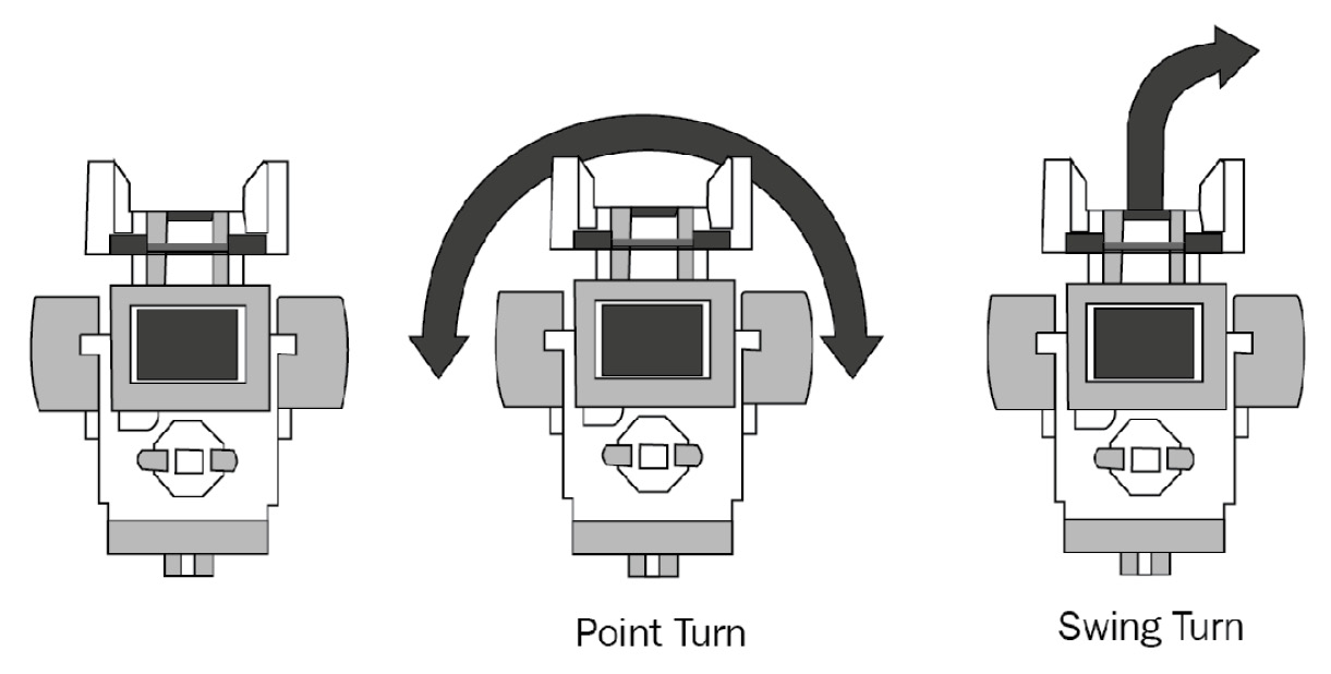
Figure 4.32 – Different types of turns
So, which direction did your robot turn? Left, or right? _________ (Space has been left for you to answer.) As the name suggests, the robot swings on one wheel to make the appropriate turns.
Did you notice the stark difference between the point and swing turns here? You will apply these turns based on your needs in the upcoming activities.
Activity 2
Program your robot to move in a square, as shown in the following diagram:
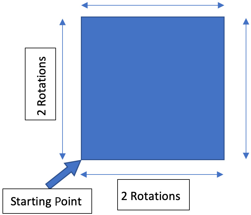
Figure 4.33 – Square shape for reference with measurements
Let's write an algorithm for this code:
- Move forward for two rotations.
- Turn right.
- Move forward for two rotations.
- Turn right.
- Move forward for two rotations.
- Turn right.
- Move forward for two rotations.
- Turn right.
Which turn will you be using here – point or swing? Since you need sharp turns at the edges of the square, you must use point turns for this activity. Follow the algorithm and write some code to make your rover move in a square shape. Did you observe something irritating in this code? You are writing the same line of code four times to form a square, hence making this code iterative. Your robot must follow the same action four times – move forward and turn right. How can we reduce these iterations and write fewer lines in the code for the same task? For such repetitive actions, we can use loops. In loop-based programming, you can write basic code that then needs to be followed n times. In the case of this square, you need to repeat an action four times. In such cases where the number of repetitions is specific, you can use a block called repeat from the Control pallet area of Scratch. Let's see how this works! Write the following code on your device:
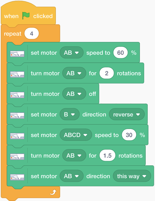
Figure 4.34 – Square shape with repetition applied
Just adjust the following parameters before running this code to form a proper square:
- Number of rotations to turn for
- Motor set in reverse
Similarly, when you want to repeat some actions forever, you must use the forever block from the Control pallet area:

Figure 4.35 – Forever loop
Try using this forever loop instead of the repeat-based loop in the same code. See what happens. Your robot will constantly move in a square shape until it is stopped by the device. Now that you are good at taking turns and using loop blocks, you may wish to write some code that makes your robot move in a rectangle shape twice:
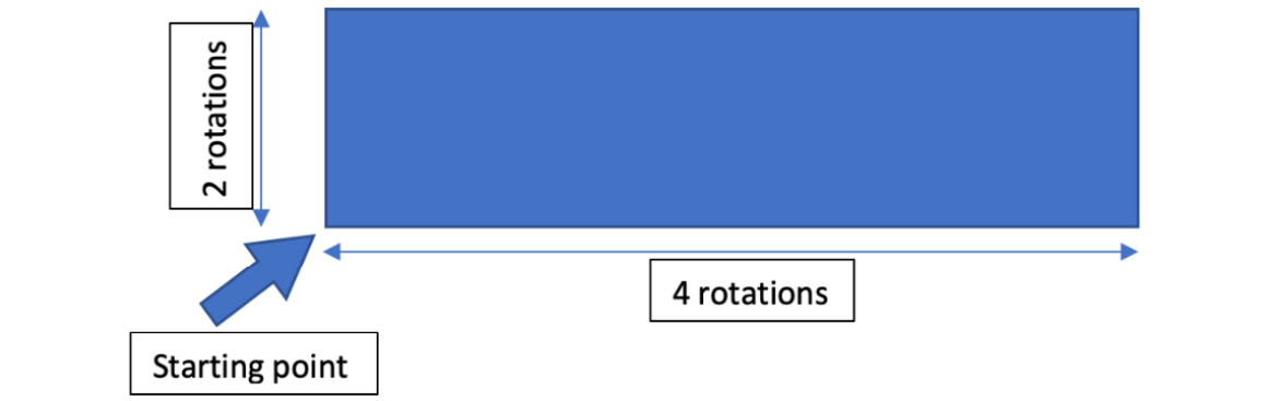
Figure 4.36 – Dimensions for the rectangle shape
It looks like you have got the hang of coding your robot to make it move in shapes with accurate turns. Try to code your robot to move in shapes such as triangles, hexagons, and diamonds with the dimensions of your choice.
Once you've done this, you can create your own path with a few left and right turns in it – some sharp, some wide – and try to run your robot through that path. This will enhance your coding skills with your BOOST kit.
Time for a challenge
Challenge #1
One more way to make turns is by simply running both motors at different speeds. By doing so, your robot will steer just like your car, instead of turning sharp at that very point. This technique can be useful when you want to make smooth, long turns of form shapes such as an arc or a circle. Either draw a big circle or find a big enough circular object in your home and try to code your rover to move around it using this technique.
Challenge #2
Can you build a seesaw using the external motor and LEGO parts in your BOOST kit? A seesaw is a common example of a simple machine lever.
Summary
In this chapter, you learned how to use wheels and axles. You applied these to your robot and built your own rover with wheels using the BOOST kit. You also learned about new programming blocks such as set motor direction, repeat loop, and forever loop. We also looked at two different types of turns that are commonly used when coding robots to make them turn; that is, point and swing turns.
In the next chapter, you will be introduced to the fascinating world of gears and how to apply them to build a geared robot. You will perform a few activities to understand concepts such as gear up and gear down. This is going to be a lot of fun!
Further reading
As we mentioned at the beginning of this chapter, there are six simple machines you can use. We covered wheels and axles in this chapter. You should learn about the other five simple machines as well by going to the following page:
https://www.britannica.com/technology/simple-machine
If you know how to practically apply these simple machines, you will be able to build your own mechanisms in the future.