
Chapter 9: Building an Automatic Entrance Door
Automatic entrance doors are used at various places, such as malls, offices, and so on. At malls, they ensure contactless entry and timely opening and closing of the door, with no human interaction required. At offices, such doors are combined with employees' identifier (ID) cards and these doors open only when the right ID card is placed in front of the door sensor, or the door stays closed. This ensures the safety of all employees in the office premises as well as helping with attendance management. In this project, you will be applying the concept of a simple machine pulley and building an entrance door that only opens when certain colors are detected. You might have seen automatic doors at malls, offices, airports, metro stations, and other places in your everyday life. Usually, an infrared (IR) sensor is used to detect the presence of a human and open/close the door. In our case, we will use a color sensor.
Do you know that distance sensors either use ultrasonic sound or IR waves to detect obstacles? They have a transmitter that emits waves, which are then reflected by an obstacle that is received by the receiver. The time difference between transmission and reception of the waves is noted, and the distance is measured using a basic formula.
You can see an automatic entrance door installation in the following screenshot:
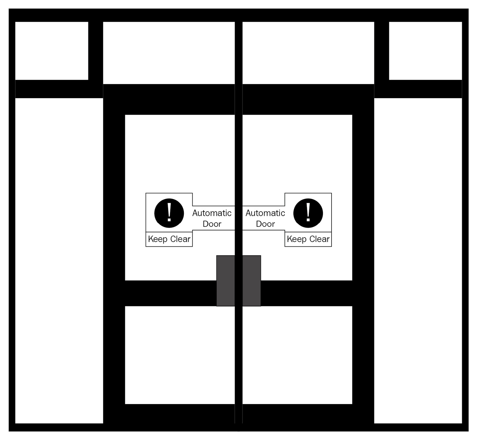
Figure 9.1 – Automatic entrance door installation
In this chapter, you will do the following:
- Building an automatic entrance door
- Let's code the door to open under certain conditions
- Time for a challenge
Technical requirements
In this chapter, you will need the following:
- LEGO BOOST kit with six AAA batteries, fully charged
- Laptop/desktop with Scratch 3.0 programming installed and an active internet connection
- A diary/notebook with pencil and eraser
Building an automatic entrance door
Let's build a door by following the building instructions given next. This is what our door should eventually look like:

Figure 9.2
We'll proceed as follows:
- Let's start our construction by taking two 1x10 bricks to make the base, as illustrated here:

Figure 9.3
- Then, take six connector pegs and connect them to the bricks, like so:
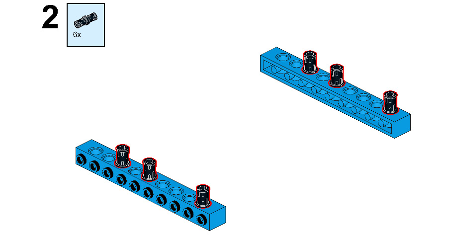
Figure 9.4
- Now, take two 1x16 bricks and connect them to each other, as follows:

Figure 9.5
- Then, take four 1x2 plates and connect them to both ends of the brick, as follows:
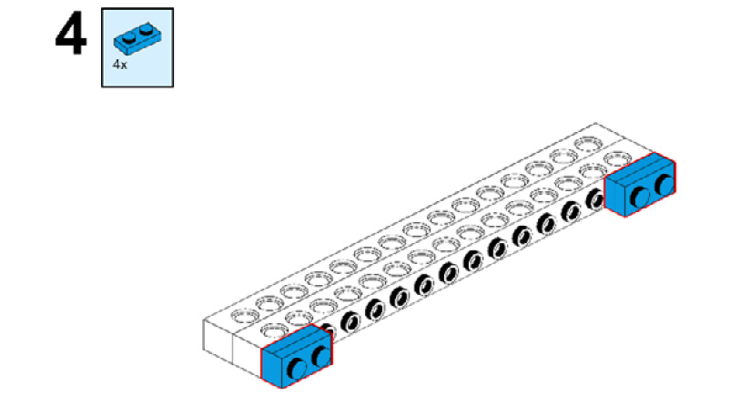
Figure 9.6
- Take two 1x2 bricks and connect them to the plates, like this:

Figure 9.7
- Now, mount this whole structure onto the blue bricks with connector pegs. Then, take two tubes with double holes and connect them with connector pegs, as illustrated here:

Figure 9.8
- Take two connector pegs and two 2M cross axles with snap, and connect them to the brick, as shown here:
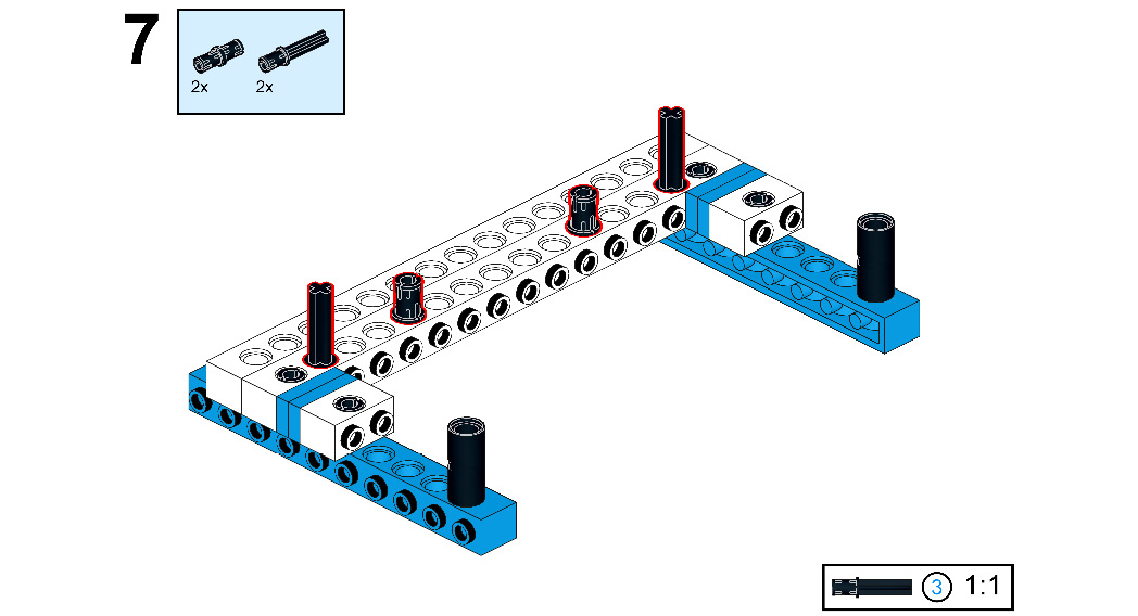
Figure 9.9
- Take two 1x2 bricks with cross holes and attach them with both the axles. Then, take one 7M beam and connect it with both the connector pegs, as shown here:
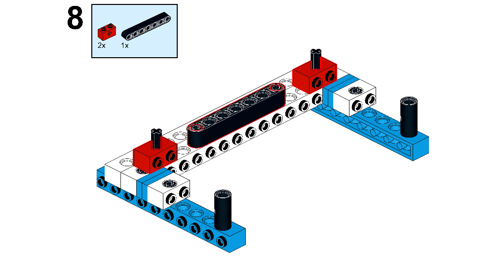
Figure 9.10
- Take two 2M cross axle connectors, connect them as shown, and then take two 7M cross axles and connect them with both the connector pegs, as follows:
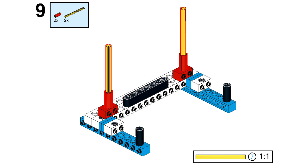
Figure 9.11
- Take two 180°-angle elements and connect them with both the axles, then take two 4M axles and connect them, as shown here:
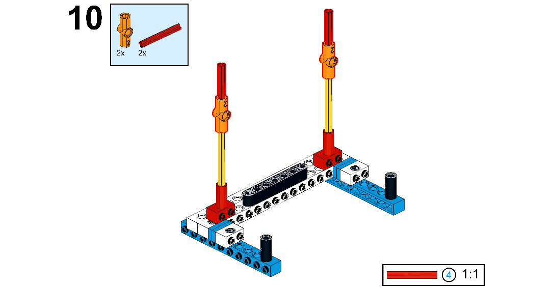
Figure 9.12
- Take two 1x2 bricks with cross holes and connect them with the axle, as shown here:
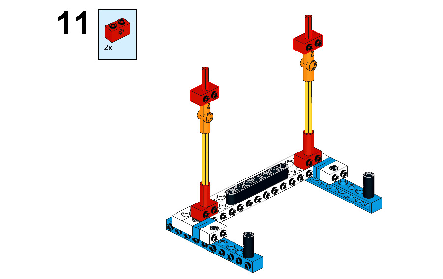
Figure 9.13
- Now, take one 7M beam and connect two connector pegs to both the ends of the beam, as follows:
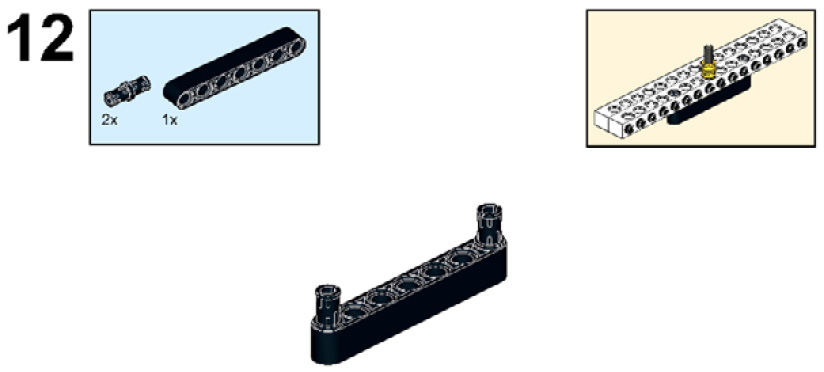
Figure 9.14
- Take one 1x16 brick and connect it to the beam, as shown here:

Figure 9.15
- Take one 4M stop axle and connect it through the 1x16 brick as well as the 7M beam, as shown in the following figure:

Figure 9.16
- Take two ½ bushes and attach them with the 4M stop axle, as follows:

Figure 9.17
- Now, take one 1x16 brick and connect it, as shown here:
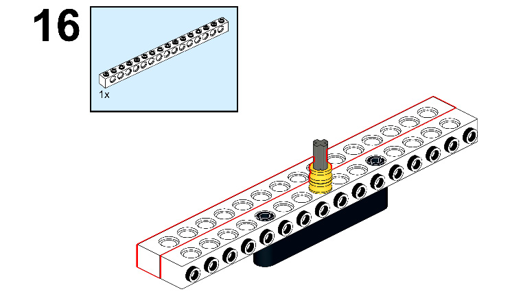
Figure 9.18
- Now, connect this whole structure with red colored axles, as shown here:
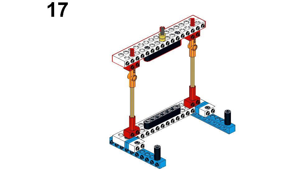
Figure 9.19
- Take 4x ½ bushes and connect them with the axles, as shown here:

Figure 9.20
- Take two 2x12 plates and connect them to the 1x2 bricks, as shown here:
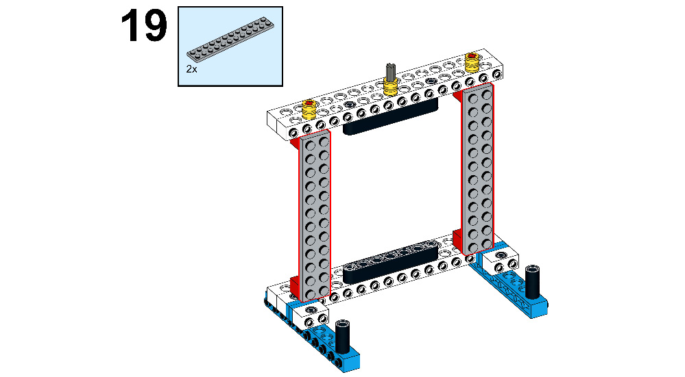
Figure 9.21
- Now, take four 2x8 plates and connect them horizontally to the 2x12 plates as shown, then take two 2x6 plates and connect them vertically to both the 2x12 plates, as follows:

Figure 9.22
- Take two 6x10 plates and connect them, as shown here:
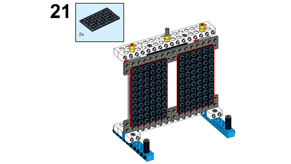
Figure 9.23
- Take four 1x10 plates and connect them, as shown here:

Figure 9.24
- Take four 1x8 plates and connect them to the top and bottom of the door, like this:
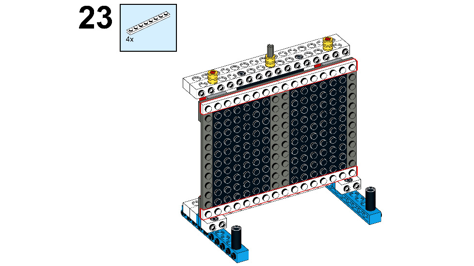
Figure 9.25
- Take four 4x4 plates and connect them to the down side of the door, as follows:
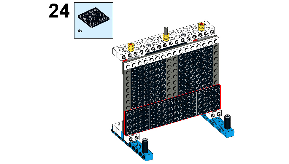
Figure 9.26
- Now, take two 2x4 plates and connect them to the top of the door, as shown. Then, take two 3x8 left plates with angles and connect them to the top-right and top-left corner of the door, respectively, as illustrated here:

Figure 9.27
- Then, take two 1x1 plates and connect them to the door, as shown here:
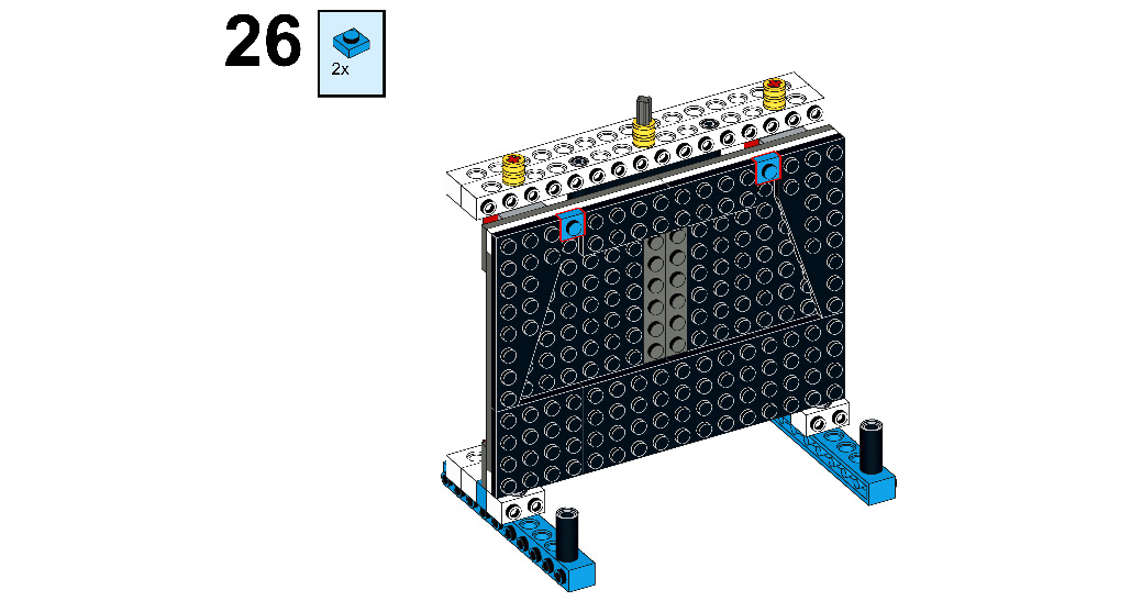
Figure 9.28
- Take four 1x4 plates and connect them to the door, as shown here:
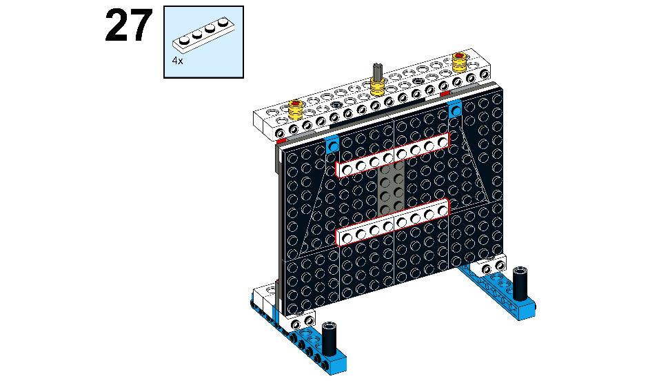
Figure 9.29
- Then, take two 1x4 plates and connect them to the door, as shown here:
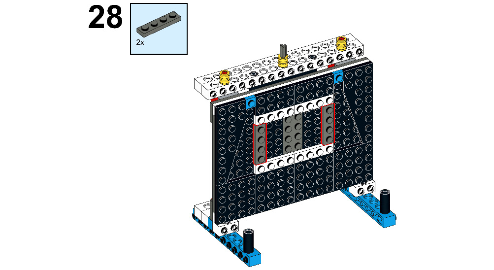
Figure 9.30
- Take two 1x8 flat tiles and connect them, as shown here:
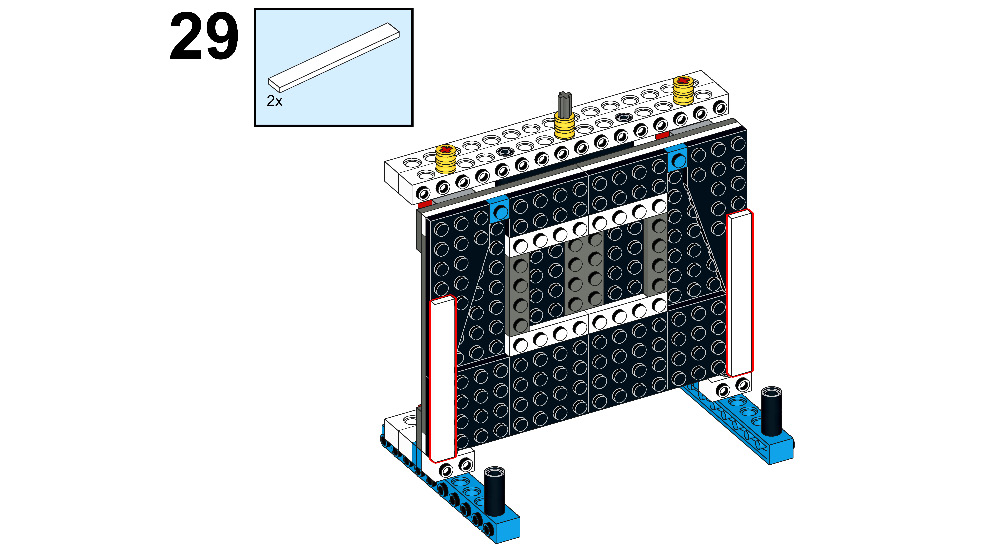
Figure 9.31
- Then, take four 1x3 flat tiles and connect them to the top-left and top-right corner of the door, as shown here:

Figure 9.32
- Now, take four 1x4 flat tiles and connect them to the door, as shown here:
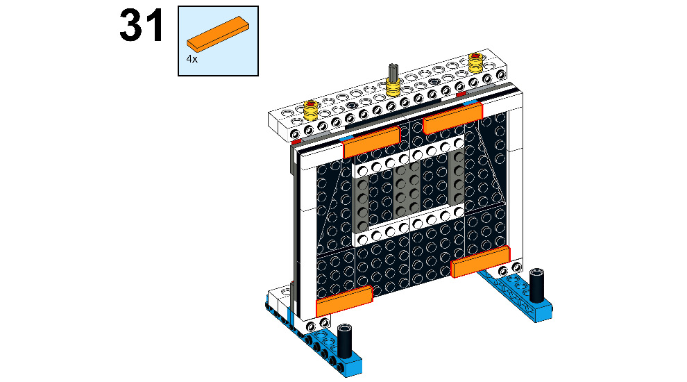
Figure 9.33
- Now, take four 1x2 flat tiles and connect them, as shown here:
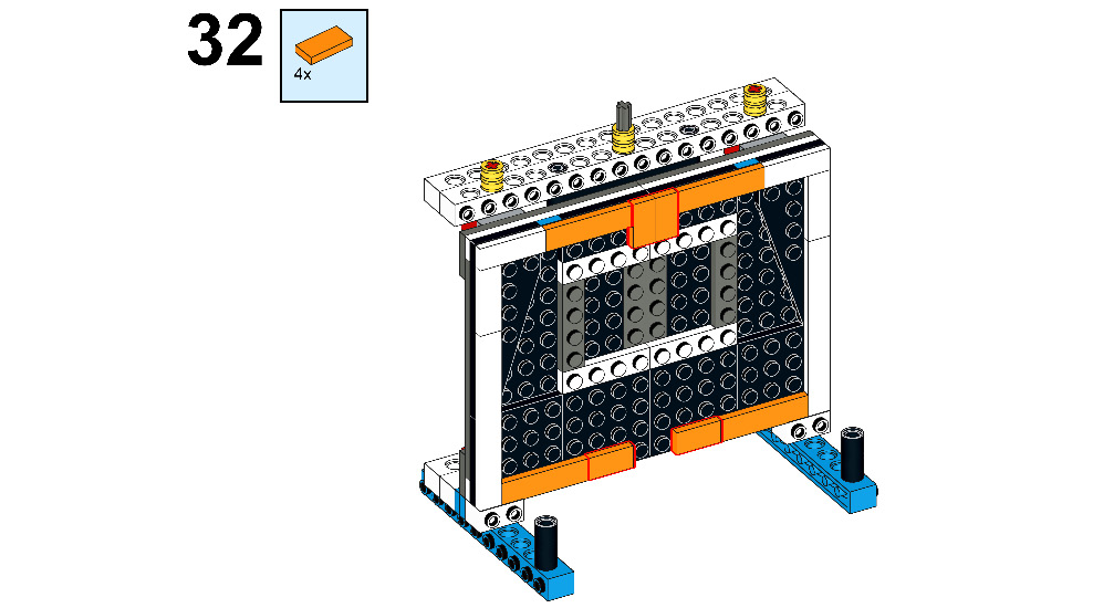
Figure 9.34
- Take two 1x4 flat tiles and connect them to the bottom edges of the door, as shown here:
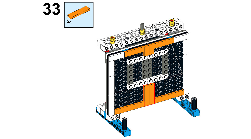
Figure 9.35
- Take four 1x4 flat tiles and connect them to the door, as shown here:
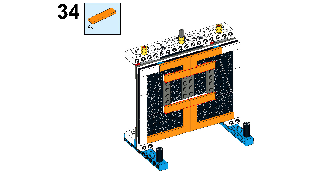
Figure 9.36
- Take two 1x4 flat tiles and two 1x4 plates with two knobs, and connect them as shown here:
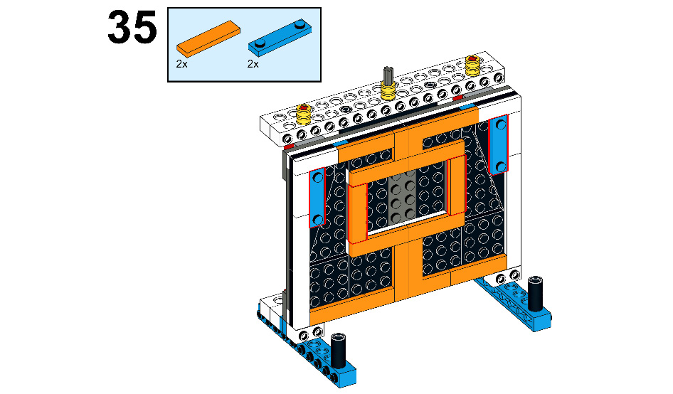
Figure 9.37
- Now, let's make handles for the door. To do that, take two 2M axles, as illustrated here:

Figure 9.38
- Then, take two design shapes with tubes and cross holes and connect them to the axle, as shown here:

Figure 9.39
- Once again, take two design shapes with tubes and cross holes and connect them, as shown here:
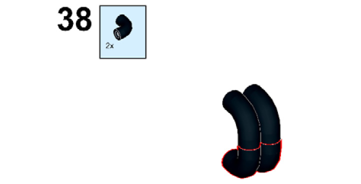
Figure 9.40
- Then, connect both the handles to the door, as shown here:
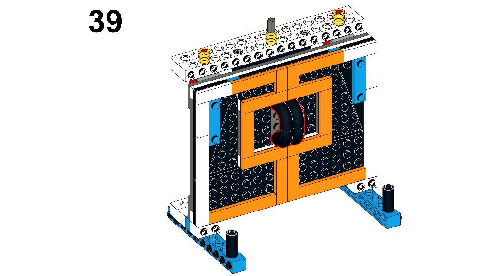
Figure 9.41
- Take two white rubber bands and connect them with half bushes, as shown here:

Figure 9.42
- Now, take an external motor from your BOOST kit and connect two 1x2 plates to the backside of the motor, as shown here:

Figure 9.43
- Then, connect the motor to the central axle of the door, as shown here:
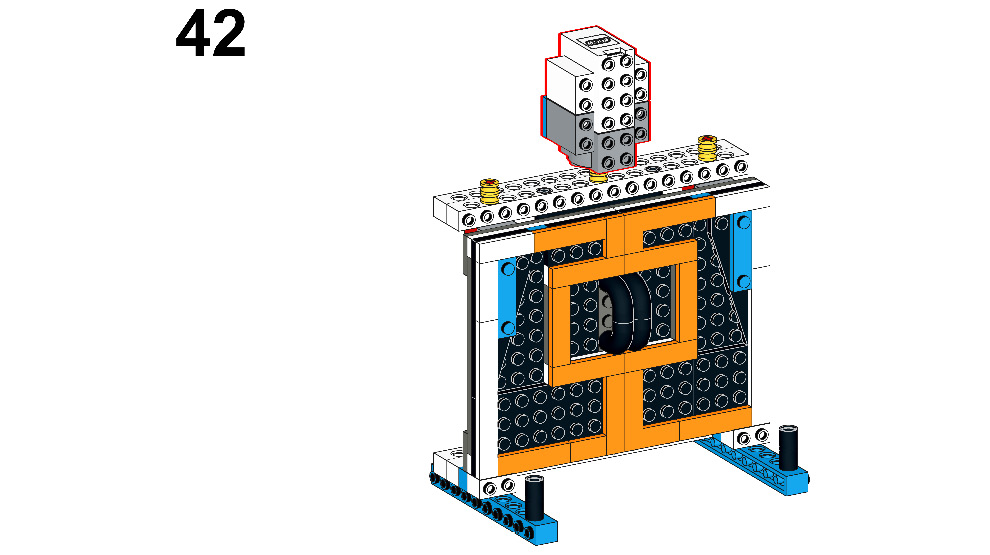
Figure 9.44
- Now, let's make it automated by attaching a sensor to it. To do that, take a 2x2 plate, as illustrated here:
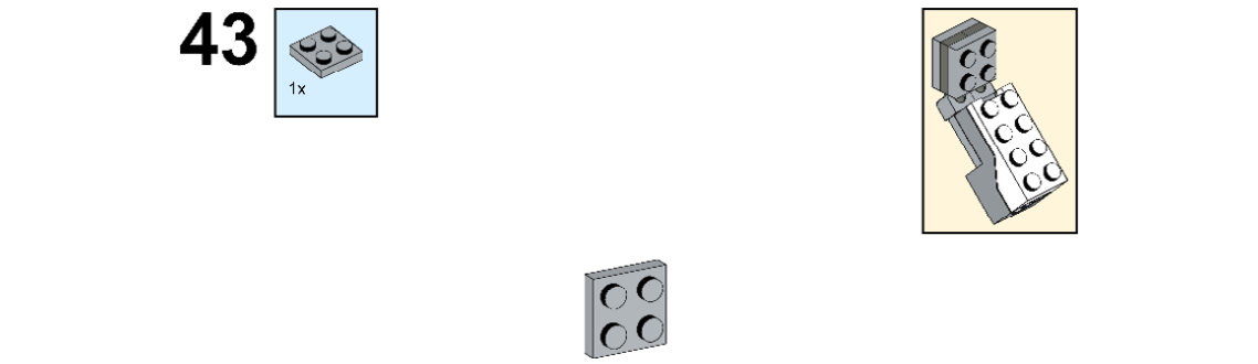
Figure 9.45
- Take two 1x2 plates with ball ends and connect them to the 2x2 plate, as follows:

Figure 9.46
- Take two 1x2 plates with ball cups and connect them to the ball-end plates, as follows:
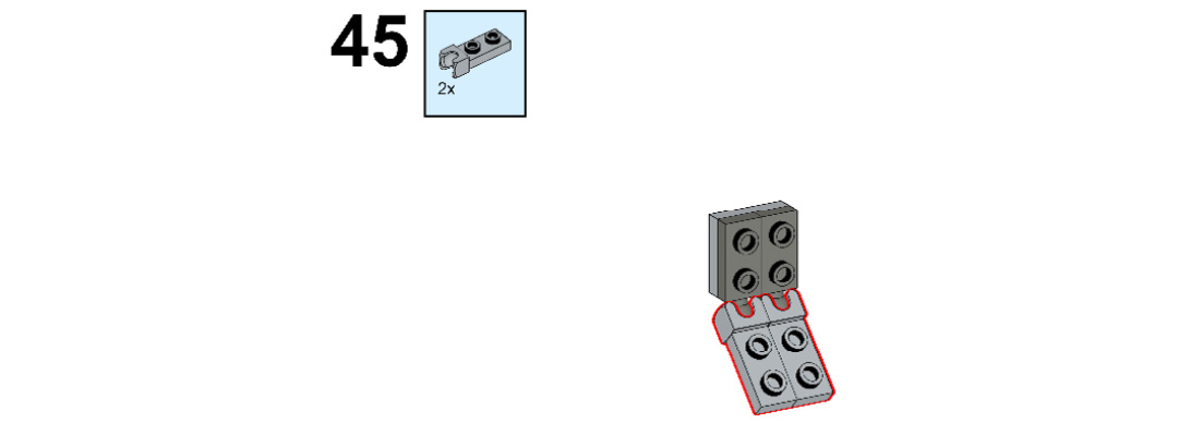
Figure 9.47
- Take one 2x2 plate and connect it, as shown here:
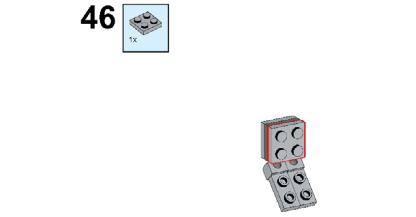
Figure 9.48
- Now, take a color sensor and connect it to the plates, as shown here:
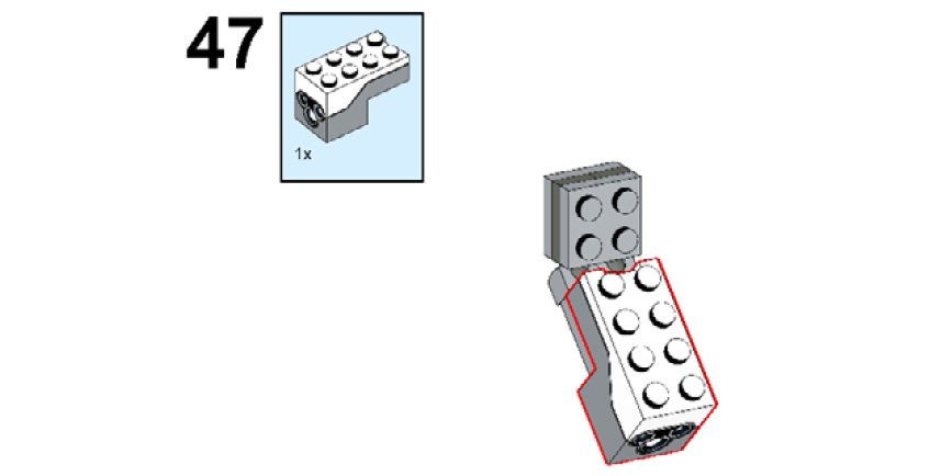
Figure 9.49
- Connect the whole structure to the external motor, as shown here:
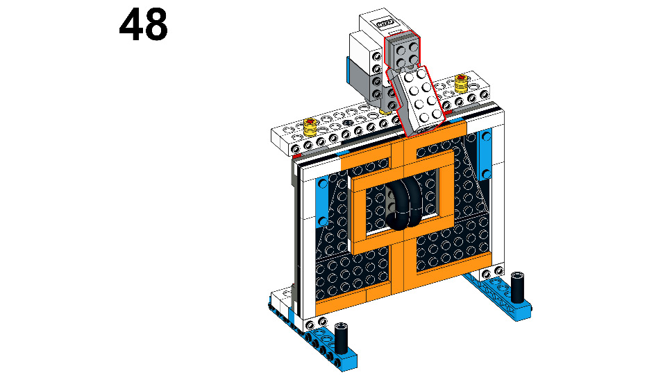
Figure 9.50
- Now, we're going to connect the BOOST Hub to the model. For that, take the hub from your kit. You can see this illustrated here:

Figure 9.51
- Take two 1x2 plates and connect them to the BOOST Hub, as shown here:

Figure 9.52
- Then, take two 1x6 plates and connect them to the 1x2 plates, as shown here:
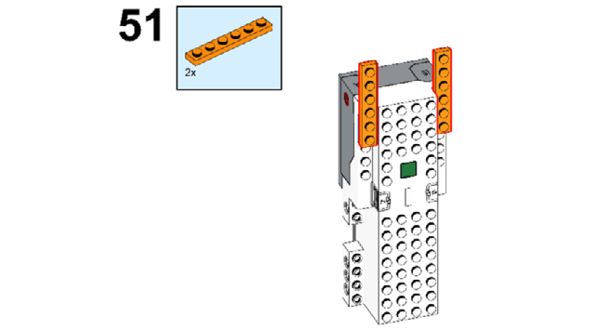
Figure 9.53
- Take one 2x6 plate and connect it to the orange plates, like this:
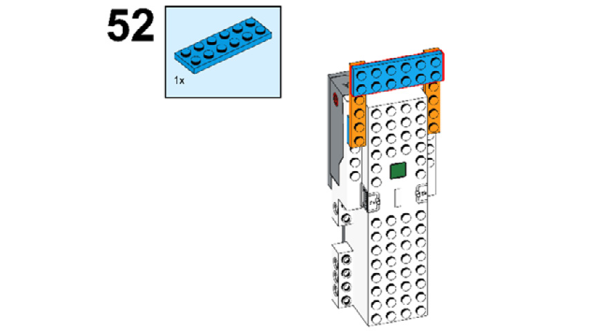
Figure 9.54
- Now, connect this structure to the motor and the base of the main model, as follows:
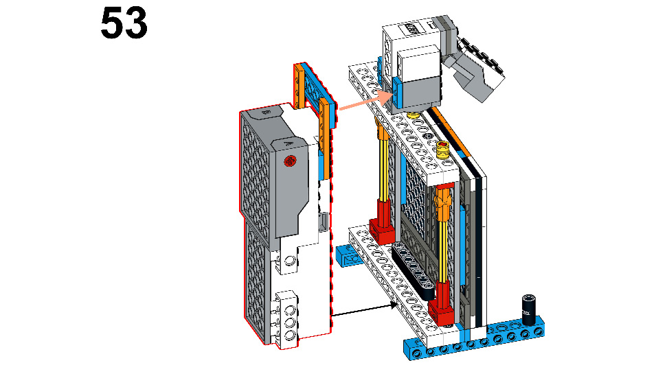
Figure 9.55
- Check the connections. If correctly connected, your model should look like this:
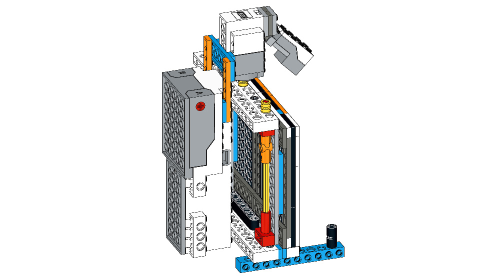
Figure 9.56
Compare your model with the model shown here:
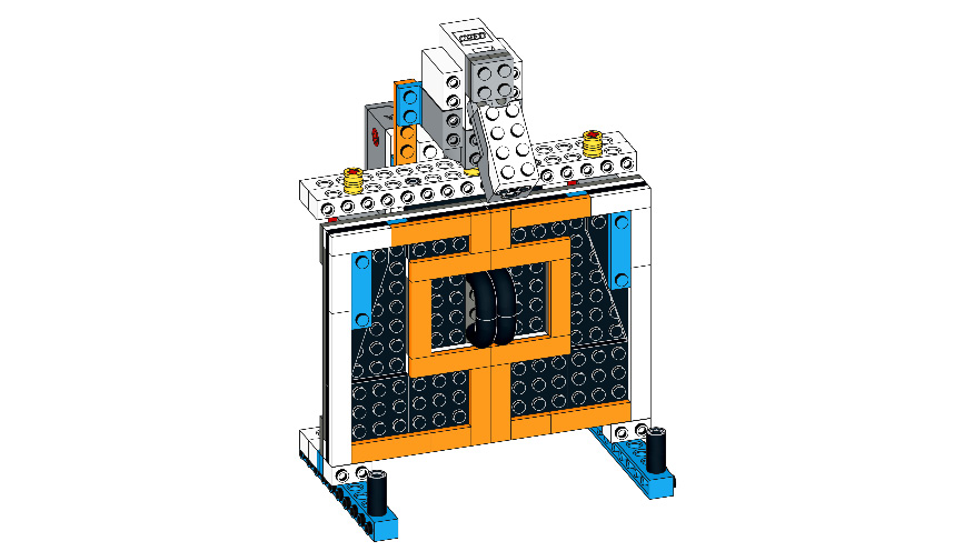
Figure 9.57
Let's now build a man to stand in front of this gate with different colored hats, using the spare LEGO bricks from your BOOST kit, as follows:
- Take two 2x6 bricks with bows and connect them, as shown here:

Figure 9.58
- Now, take two 2x4 plates with holes and connect them to the 2x6 bricks with bows, as follows:
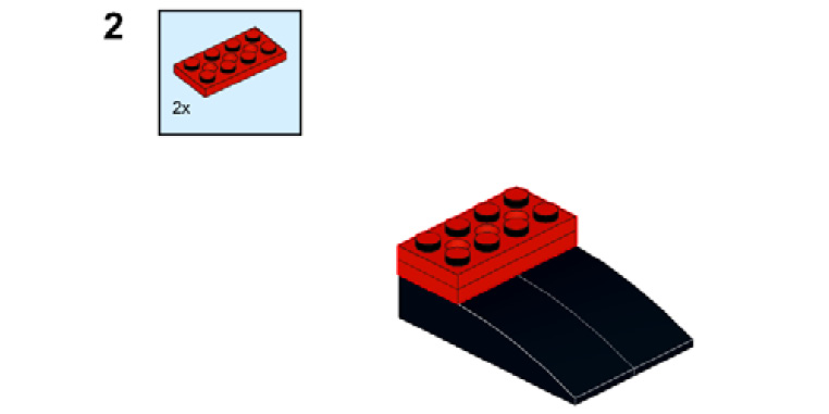
Figure 9.59
- Take two connector pegs and connect them to the first and third holes of the upper 2x4 plate, as follows:
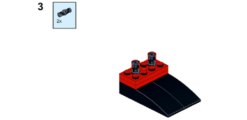
Figure 9.60
- Take two connector pegs and one 4x6 brick. Connect the 4x6 brick to the recently attached connector peg, and on the 4x6 brick, connect two connector pegs, as illustrated here:
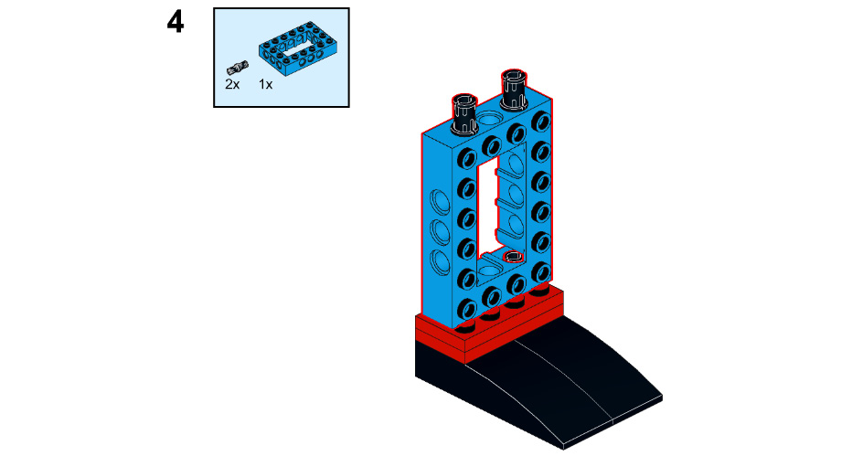
Figure 9.61
- Take four connector pegs and one 4x6 brick. Connect the 4x6 brick to the recently attached connector peg, and on both sides of the 4x6 brick, connect four connector pegs, as illustrated here:
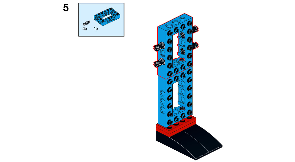
Figure 9.62
- Take two 6M flex joints and connect these to each side of the connector peg, as illustrated here:
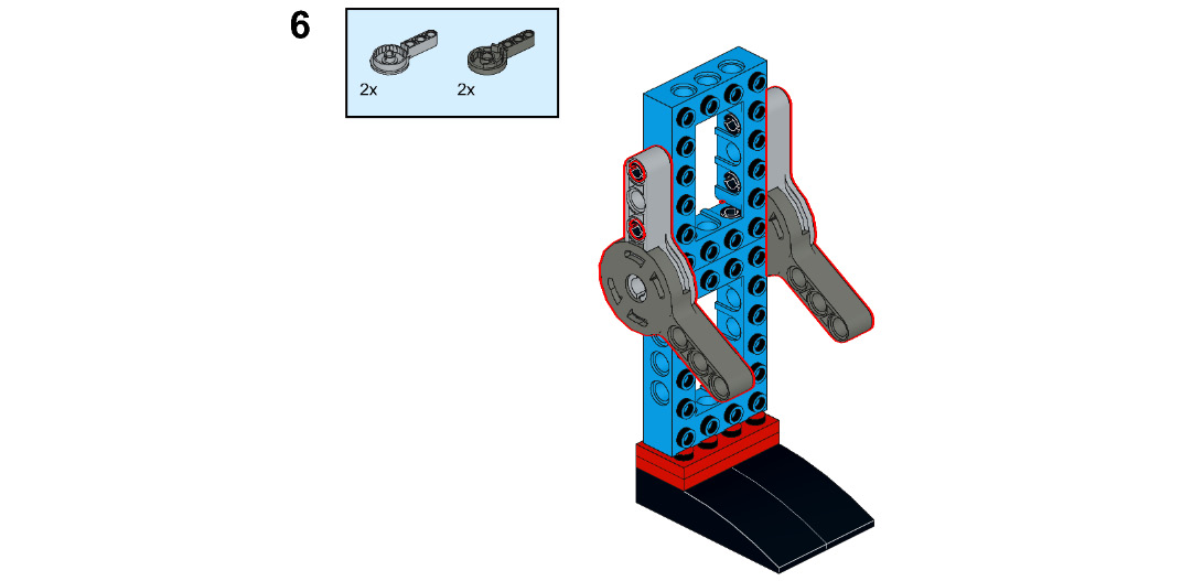
Figure 9.63
- Take two connector pegs and connect them to the 4x6 brick, as shown here:
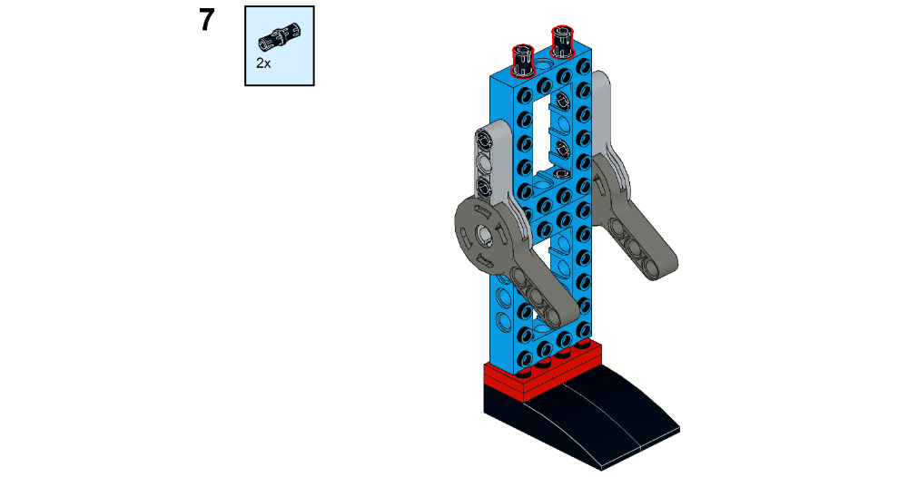
Figure 9.64
- Now, take one 2x4 blue tile, one 2x4 green tile, one 2x4 red tile, one 2x4 yellow tile, one 2x4 white tile, and one 2x4 brick. Connect the 2x4 brick to the recently attached connector peg and then connect the flat tile to the 4x6 brick, as shown here:

Figure 9.65
- Take four 1x1 flat round tiles and one 1x2 brick. Connect the 1x2 brick to the 2x4 brick and connect the 1x1 flat round tile to the 4x6 brick, as shown here:
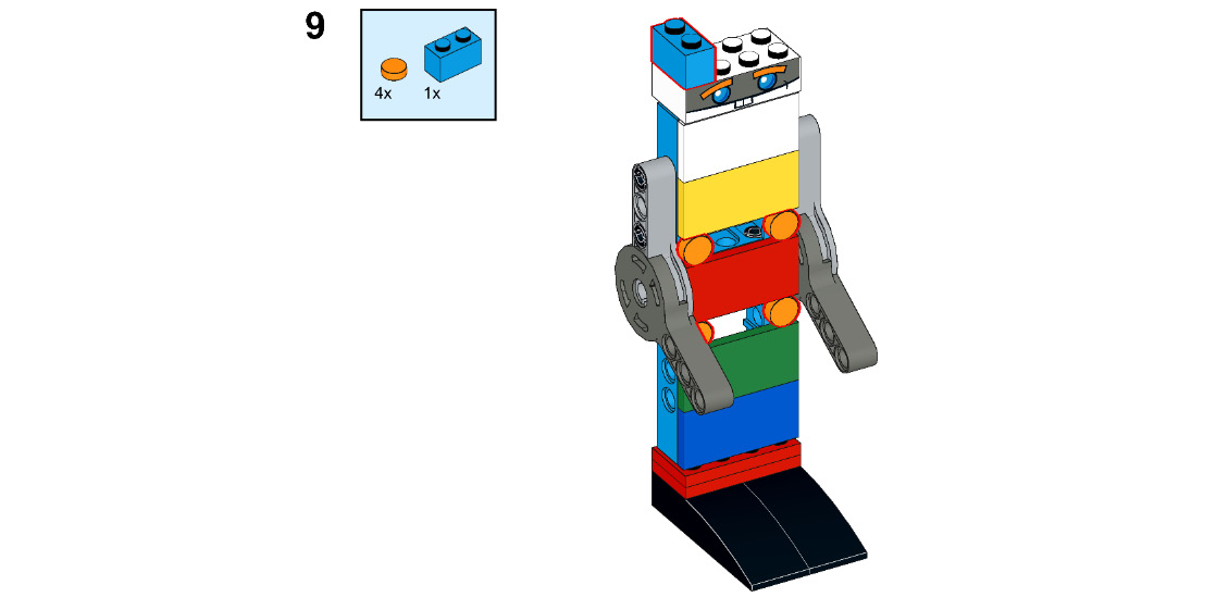
Figure 9.66
- Now, take three 1x2 plates and one 2x4 brick with bow. Connect the three 1x2 plates to the 2x4 brick and then connect the 2x4 brick with bow to the 1x2 plate, as illustrated here:
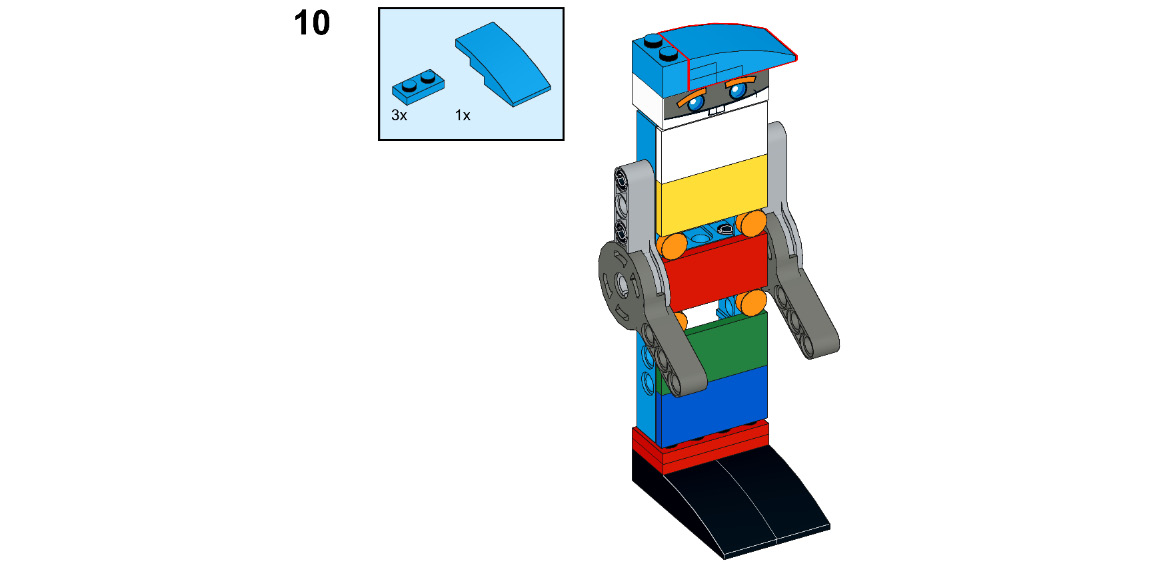
Figure 9.67
Now, let's program this door to open only under certain conditions.
Let's code the door to open under certain conditions
Let's first find out the number of rotations needed to open and close the door completely. Keep the motor power at 30% only. We will need the following number of rotations:
__________ rotations to open the door fully
__________ rotations to close the door fully
Great! Now, do the setup of your automatic door and the color-coded man, as shown in the following screenshot. Identify the right place for the man to stand so that the color sensor can detect the colors accurately. The sensor should be able to sense the color of the hat:
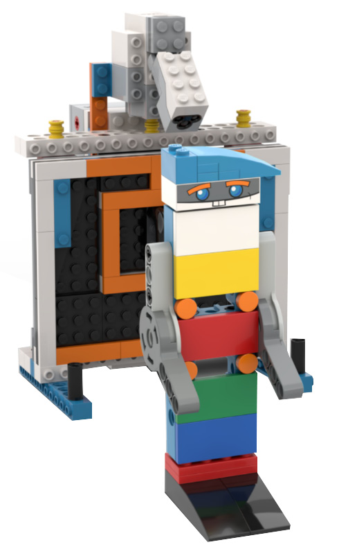
Figure 9.68 – Basic setup of the man and door
Let's first understand the basics of the color sensor and how it works. Your BOOST kit's color sensor can detect six different colors: red, blue, green, yellow, black, and white. It can detect color from a maximum distance of 3 cm. Let's now learn how to code. For sensor-based programming, the first and foremost thing to understand is that the movement of your robot will neither be rotation-based nor seconds-based. So, what will be the logic? Let's understand this with an example. If you want to stop your robot moving when it senses a red color, your basic algorithm will be this:
Move forward until the robot senses a red color. When red is sensed, stop moving.
Based on this, we will write the program. You will be using blocks such as wait until, if, if-else, and repeat until from the Control pallet and seeing any color brick from the BOOST pallet. These blocks can be seen in the following screenshot:
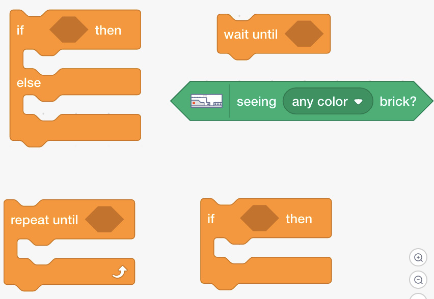
Figure 9.69 – Blocks to use for sensor-based programing
These blocks will help in decision making based on the inputs received from the sensor. If-else is a conditional statement for the decisions. Wait until is a block which executes the block above it, until the condition inside the wait until block is fulfilled. Similarly, repeat until block repeats the execution of the blocks inside this repeat block, until the specified condition is met. Use of these blocks will be made more clear in the upcoming activities as well as projects. Let us now move on to write our first sensor based programming.
Activity #1
Write a program to open the door when a blue color is detected. Keep it open for 3 seconds and then close the door. Display a warning message/play a sound file of your choice before closing the door.
The sample code for this activity is given here:
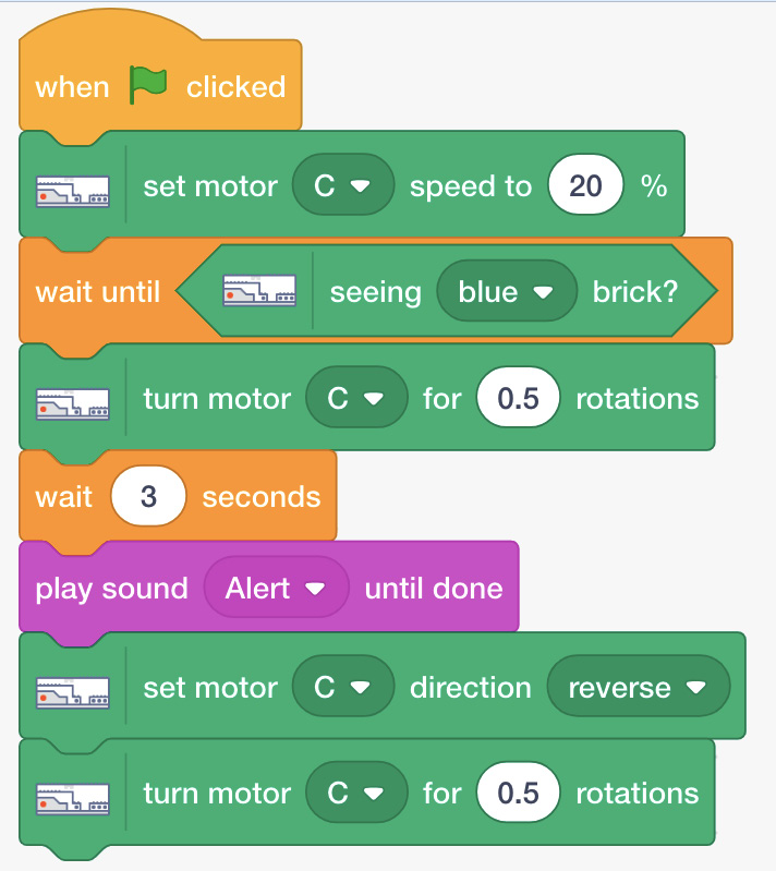
Figure 9.70 – Sample code
Do you remember seeing an if-then block in the Control pallet? We will be using this block for the next activity.
Activity #2
Open and close the door for different durations for different colors sensed—for example, 2 seconds if blue is detected, 4 seconds if red is detected, and 7 seconds if green is detected.
Basic sample code to perform this activity is illustrated here:
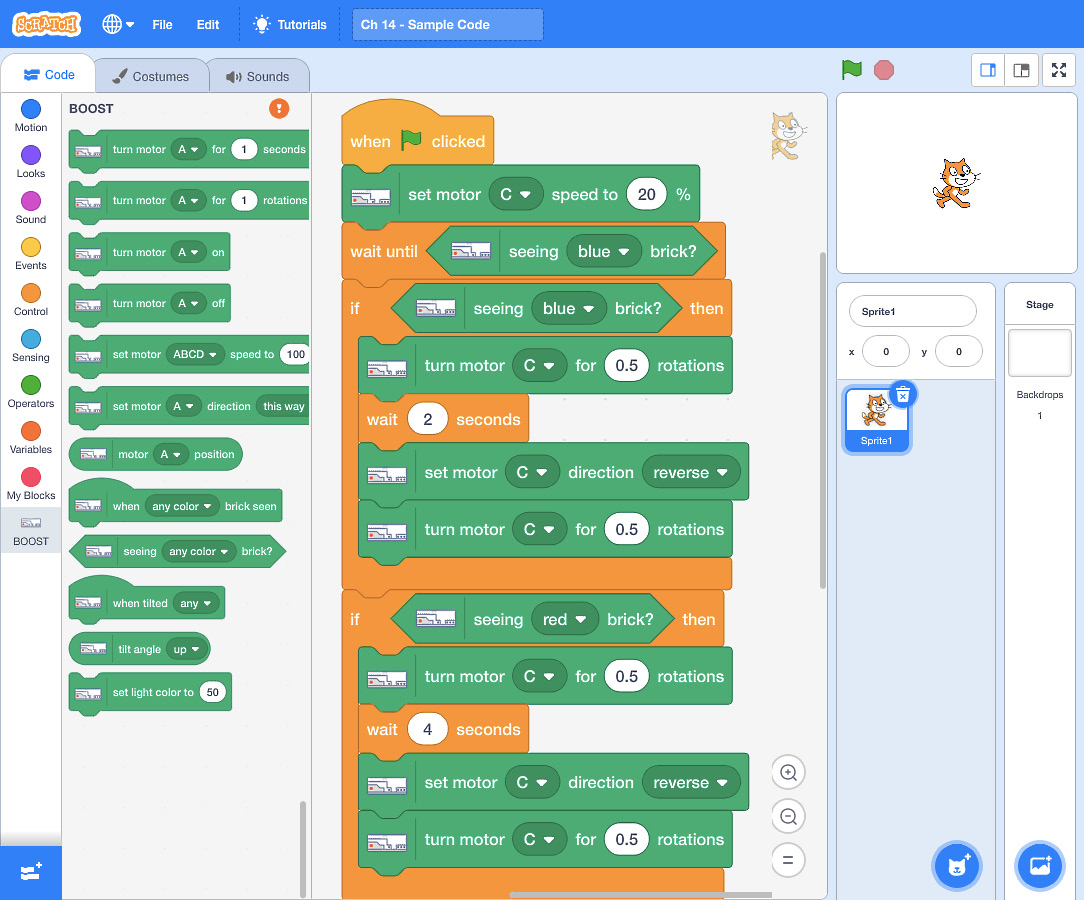
Figure 9.71 – Sample code
Here is a sample code for keeping the door open for 7 seconds when green is detected:
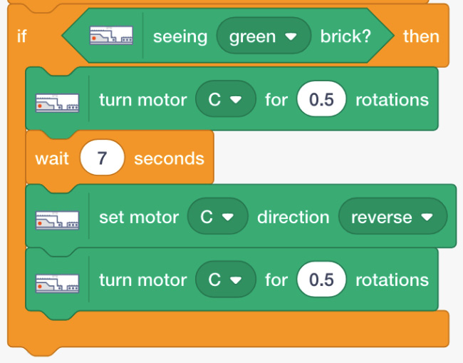
Figure 9.72 – Sample code
You can simply remove the blue hat and change the hat colors accordingly. Refer to the following screenshot:
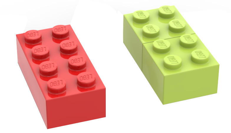
Figure 9.73 – LEGO bricks for hat colors
You can cascade multiple if-then blocks for various conditions that you wish to implement for your robot. Let's now solve the final challenge.
Time for a challenge
Challenge #1
Assume that a door is fixed at an office and the owner wants to allow entry of only specific types of people into the office. So now, program your door to do the following:
- Open when it senses people with green and blue hats.
- Keep the door closed for people with red hats. Display Sorry, entry is restricted to such people.
You need to use the same man that you built using the BOOST elements. Keep changing the hat color to test it.
Challenge #2
Try to add more colored hats, such as black, white, and yellow hats, using your LEGO elements, and modify the list as follows:
- Open the door for people with blue, green, and yellow hats.
- Keep the door closed for people with white, black, and red hats. You can display the same warning message.
You can use more of these if-else statements and add to the decision-making capabilities of your BOOST robot for many such exciting projects.
Summary
In this chapter, you worked further with the color sensor and wrote programs for complex tasks with multiple decisions involved. You used an if-then block for the first time. You also wrote programs for different actions of the robot for different colors detected. A pulley mechanism was used to open and close the doors. You understood the practical application of automatic doors in this chapter. To further instill these concepts, you will be building and coding a candy dispenser in the next chapter that will dispense candy depending on the color-coded currency detected.
Further reading
Most companies give a radio-frequency identification (RFID)-based ID card to their employees so that it becomes easy to track their attendance as well as ensure entry of only authorized people into the office. You can find out more about how RFID works at https://lowrysolutions.com/blog/how-rfid-and-rfid-readers-actually-work/.
Ready-made RFID tags are available on the market. You can interface them with an Arduino programming board and build your own RFID-enabled items in the future.